A Statistical Approach for Gain Bandwidth Prediction of Phoenix-Cell Based Reflect arrays

Adv. Sci. Technol. Eng. Syst. J. 3(1), 103–108 (2018);
 DOI: 10.25046/aj030112
A new statistical approach to predict the gain bandwidth of Phoenix-cell based reflectarrays is proposed. It combines the effects of both main factors that limit the bandwidth of reflectarrays: spatial phase delays and intrinsic bandwidth of radiating cells. As an illustration, the proposed approach is successfully applied to two reflectarrays based on new Phoenix cells.
1. Introduction
This paper is an extension of work originally presented in the 11th European Conference on Antennas and Propagation (EuCAP) where a novel single layer stub-patch Phoenix cell is suggested as a broadband and easy solution to fabricate reflectarray (RA) elements [1].
The Phoenix cell concept was firstly introduced in [2] and many other Phoenix cells were derived later [3-8]. As their name suggests, Phoenix cells are characterized by rebirth capabilities, which means that their geometry comes back to its initial state after a complete 360° phase cycle. This guarantees a smooth evolution of cell geometries over the RA panel and prevents perturbations in the radiation pattern. Phoenix cells are also characterized by a quasi-linear phase response which classifies them as broadband RA cells. Nevertheless, as for other broadband cells, their phase response is still not totally perfect and the proper assessment of the residual phase error versus frequency is still missing in the literature.
In this paper, this last issue is addressed and a new statistical approach for estimating the bandwidth of RA based on Phoenix cells is proposed. The suggested approach relies on the standard deviation of phase errors over the RA panel and combines the effects of both bandwidth limiting factors: the dispersion of spatial phase delays with frequency [9] and the intrinsic limited bandwidth of cells themselves [10]. This standard deviation is shown to provide a promising figure of merit, better than those in [9, 10] where only the maximum phase error due to spatial delays is taken into account.
The paper is organized as follows. In section 2, the new statistical approach is defined. In sections 3 and 4, a bandwidth estimator for RA gain is derived. Finally, in section 5, it is validated by comparison with the simulated bandwidth of a test-case RA based on two different Phoenix cell topologies.
2. Statistical Bandwidth Estimator
Consider an N-cell circular RA of diameter D with a feeding antenna positioned at distance F normally above the array center. The phase of the wave radiated by cell i at central frequency f0 is defined as:
![]() where is the phase-shift produced by the cell and is the phase of the incident wave defined as:
where is the phase-shift produced by the cell and is the phase of the incident wave defined as:
![]() In these equations, ρi is the radial distance between the center of the array and cell i and c is the velocity of light in vacuum.
In these equations, ρi is the radial distance between the center of the array and cell i and c is the velocity of light in vacuum.
In order to produce a desired radiation pattern, the required radiated phases are usually specified at f0 and the subsequent phase-shifts are directly deduced from (1) and (2). The cells are selected accordingly and appropriately distributed over the RA.
When the frequency is shifted to f=f0+Δf, the phase radiated by cell i is changed by as:
![]() where is the predictable deviation of the phase of the incident wave defined as:
where is the predictable deviation of the phase of the incident wave defined as:
![]() while is the cell-dependent phase deviation due to the cell’s dispersive phase response. At the RA level, these phase errors are responsible for a decrease of the gain at f, and thus for the limited bandwidth.
while is the cell-dependent phase deviation due to the cell’s dispersive phase response. At the RA level, these phase errors are responsible for a decrease of the gain at f, and thus for the limited bandwidth.
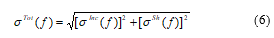
The bandwidth estimator we propose is derived from the standard deviation of the total phase error. Let , , and be the statistical variables related to the total, incident and phase-shift errors at f respectively. , and are the respective standard deviations. Using (3), the standard deviation of the total error can be expressed as:
![]() Assuming and are uncorrelated, which is the case when the synthesis process is done at f0 only, as usually applied in the literature [11-15], the covariance term reduces to zero and reduces consequently to:
Assuming and are uncorrelated, which is the case when the synthesis process is done at f0 only, as usually applied in the literature [11-15], the covariance term reduces to zero and reduces consequently to:
 3. Bandwidth Estimator: Incident Phase Errors
3.1. Standard Deviation of Incident Phase Errors
Defining:
![]() (4) can be reformulated as:
(4) can be reformulated as:
![]() Due to the mathematical properties of standard deviation, can be derived as:
Due to the mathematical properties of standard deviation, can be derived as:
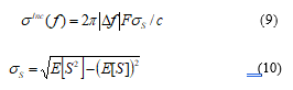 E[S] and E[S2] are the first statistical moments and can be calculated as:
 Note that σS does not depend on frequency but only on the dimensions of the RA, which is consistent with other criteria in the literature [10]. Note also that, in (11) and (12), a rectangular lattice is considered and ρi is consequently supposed to vary uniformly in the [0, D/2] range. In addition, though ρi is normally a discrete variable, it is assumed here to vary continuously. This assumption is reasonable since the inter-element spacing is usually a small fraction of λ0 (which is much lower than D/2). Furthermore, as in [9] and [10] and for simplicity reasons, Si and the resulting σS are calculated for a centered fed RA. Different expressions could easily be established for offset configurations.
3.2. Bandwidth Estimator
We now investigate how the gain deteriorates with respect to . To do so, we consider the gain at broadside for a test-case RA with 12mm spacing (i.e. 0.5λ0 at the center of the [11-14] GHz frequency band). Edge tapering is supposed to be -12dB and different antenna configurations are considered: F/D=0.6 and 0.8 with D varying from 0.28m≈ 12λ0 to 1m ≈ 42λ0. For each couple (F/D; D), the reflected field (phase and magnitude) in the aperture is calculated and the associated gain is derived using simple array theory (as in [16]). Simultaneously, is also computed as the standard deviation of all phase errors. Finally, Figure 1 gives the representation of the normalized simulated gain G(f)/G(f0) versus the corresponding standard deviation .
Figure 1. Simulated gain decrease with respect to the standard deviation of incident phase errors (F/D=0.8 or F/D=0.6).
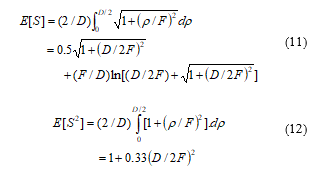
An important conclusion from Figure 1 is that all curves superimpose whatever the particular values of D, F or f. This demonstrates that is a reliable estimator for the bandwidth since it directly reflects the gain decrease. Figure 1 also shows that a 1dB gain-drop approximately corresponds to =π/6. As a consequence, the upper frequency fmax of the -1dB bandwidth may be derived simply by replacing by π/6 in (9), leading to:
 Equation (13) will thus be used as a bandwidth estimator. At this stage, it does not depend on any particular cell topology but only on the spatial phase delay error. As will be seen now, this initial estimator can advantageously be replaced by a more sophisticated one that also accounts for the phase dispersion of the used RA cells. In what follows, the case of cells with an ideal phase response is considered.
4. Bandwidth Estimator: Total Phase Errors
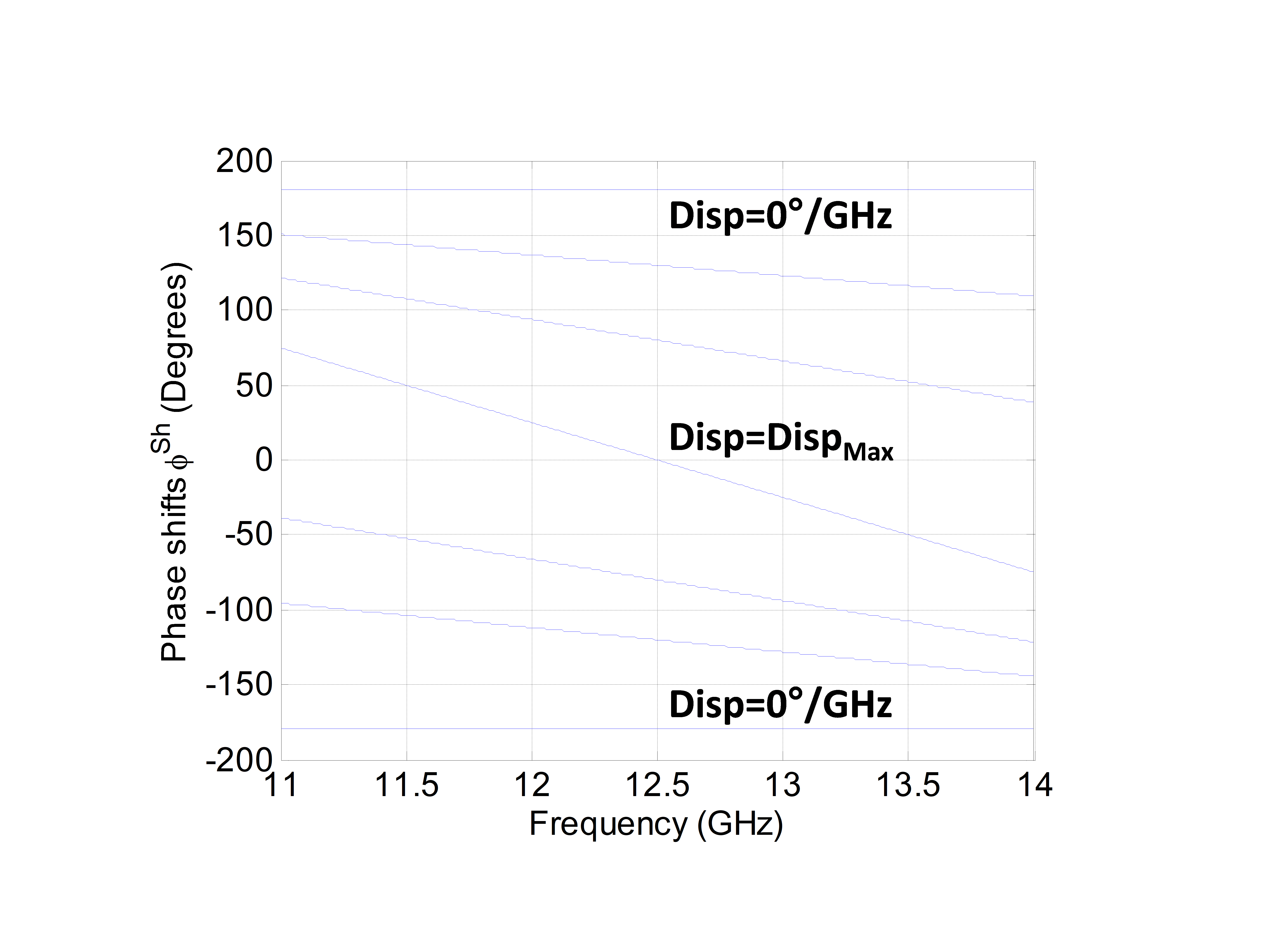 Figure 2. Linear phase response of an ideal Phoenix cell.
The ideal cell we suggest here is quite representative of Phoenix cells as will be shown in section 5. It is supposed to provide a phase range of at least 360° at f0 and perfect linear variations with respect to frequency. Figure 2 shows the phase response versus frequency of the ideal cell. As such, the phase-shift error for cell i at frequency f can be expressed as:
![]() where Dispi is the dispersion that is supposed to vary uniformly in the interval [0-Dispmax]. More specifically, Dispi is considered to be equal to 0°/GHz for phase-shifts = ±180° and to reach its maximum (i.e. Dispmax) when = 0°. Note that the perfect Phoenix cell is obtained when Dispmax= 0°/GHz as all its phase states would be perfectly parallel.
where Dispi is the dispersion that is supposed to vary uniformly in the interval [0-Dispmax]. More specifically, Dispi is considered to be equal to 0°/GHz for phase-shifts = ±180° and to reach its maximum (i.e. Dispmax) when = 0°. Note that the perfect Phoenix cell is obtained when Dispmax= 0°/GHz as all its phase states would be perfectly parallel.
Assuming all phase-shifts are equally probable on the radiating aperture, can be expressed as:
![]() Using (9) and (16) in (6), a generalized bandwidth estimator accounting for both types of errors is derived:
Using (9) and (16) in (6), a generalized bandwidth estimator accounting for both types of errors is derived:
![]() Finally, is set to π/6 as already done in Part 3.2 to obtain the generalized bandwidth estimator:
Finally, is set to π/6 as already done in Part 3.2 to obtain the generalized bandwidth estimator:
![]() To validate (18), the gain decrease simulation described in Section 3.2 is repeated (as in [16]), now accounting for both types of phase errors. The associated simulated -1dB gain bandwidth is then extracted and compared to the theoretical value predicted from (18). In this study, F/D is set to 0.8, D varies from 0.16m to 1m (i.e. ~7λ0 to 42λ0) and Dispmax varies from 0˚/GHz to 100˚/GHz. Figure 3 shows that the difference between simulation and theory is less than 3%, even for the highest dispersion and the smallest diameter values.
To validate (18), the gain decrease simulation described in Section 3.2 is repeated (as in [16]), now accounting for both types of phase errors. The associated simulated -1dB gain bandwidth is then extracted and compared to the theoretical value predicted from (18). In this study, F/D is set to 0.8, D varies from 0.16m to 1m (i.e. ~7λ0 to 42λ0) and Dispmax varies from 0˚/GHz to 100˚/GHz. Figure 3 shows that the difference between simulation and theory is less than 3%, even for the highest dispersion and the smallest diameter values.
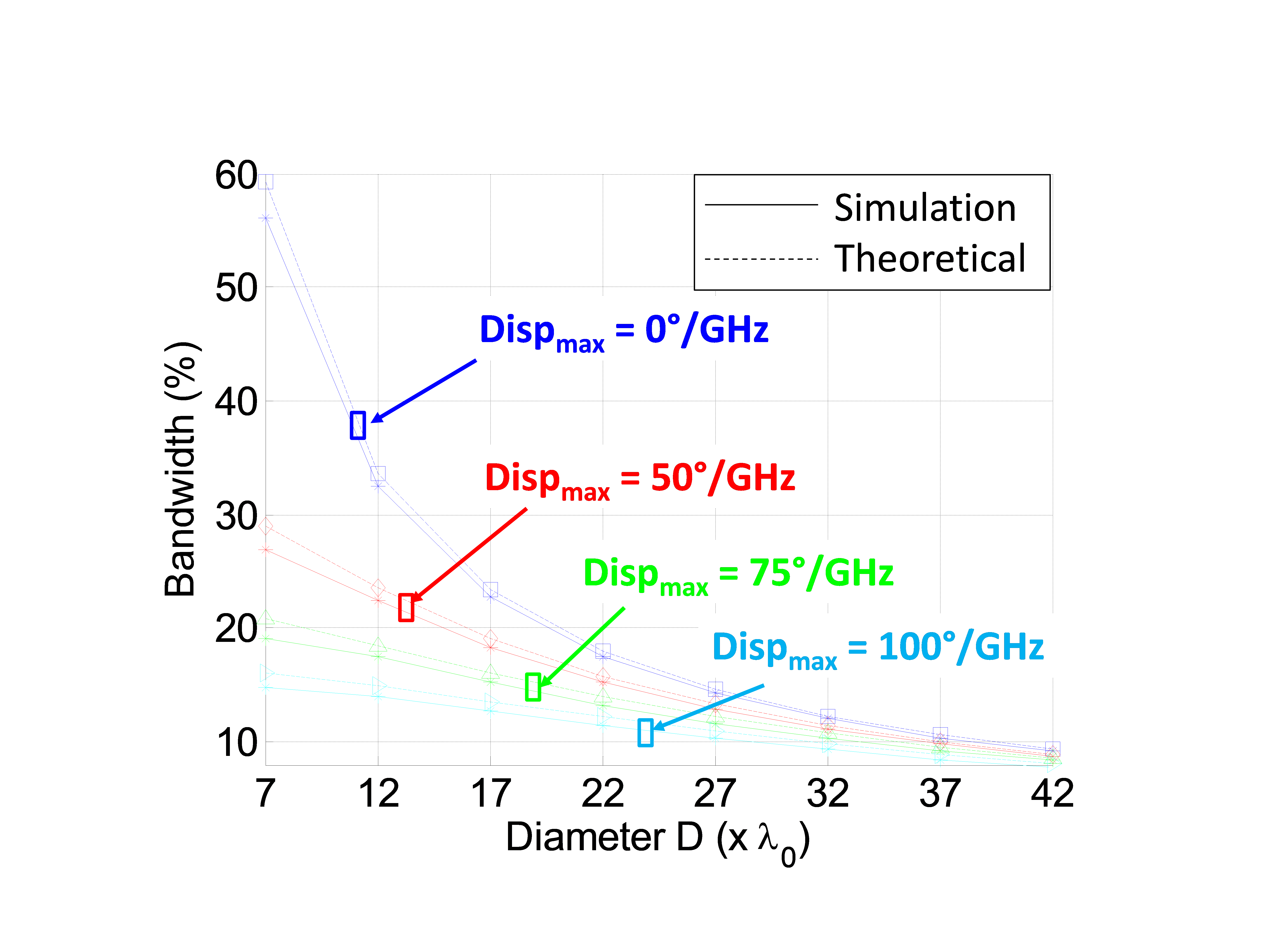 Figure 3. Total phase errors effects: simulated and theoretical bandwidths (F/D=0.8).
As a conclusion, (18) appears to be a reliable bandwidth estimator. In practice, it can be used to define the maximum acceptable cell dispersion for a given application. As an example, for a RA with D=22λ0 and F/D = 0.8, the cell dispersion should be less than 50°/GHz to ensure a 15% bandwidth.
5. Practical Validation
In practice, the phase response of Phoenix cells is not purely linear as in the previously-used ideal cell model. Therefore, to assess the validity of our approach, the actual performance of two recently-proposed Phoenix cells is assessed and compared to those obtained using (18).
The two cells are designed to operate around a central frequency f0 = 12.5GHz, with λ0/2 spacing at f0. Both cells are printed on a Duroïd substrate with 2.17 dielectric constant and backed by a ground plane. The substrate height is fixed to 4 mm. This corresponds to approximately λ0/(4 , which means the reflected phase is close to 0° if the cell is transparent.
To extract the phase responses, both cells are simulated using ANSYS-HFSS software assuming normal incidence and local periodicity. As Phoenix cells allow for smooth evolution of cell geometries over the RA panel, it is assumed that the phase responses obtained by simulation are valid for finite reflectarray configurations [2].
5.1. Cell 1: Slot – Patch Phoenix Cell
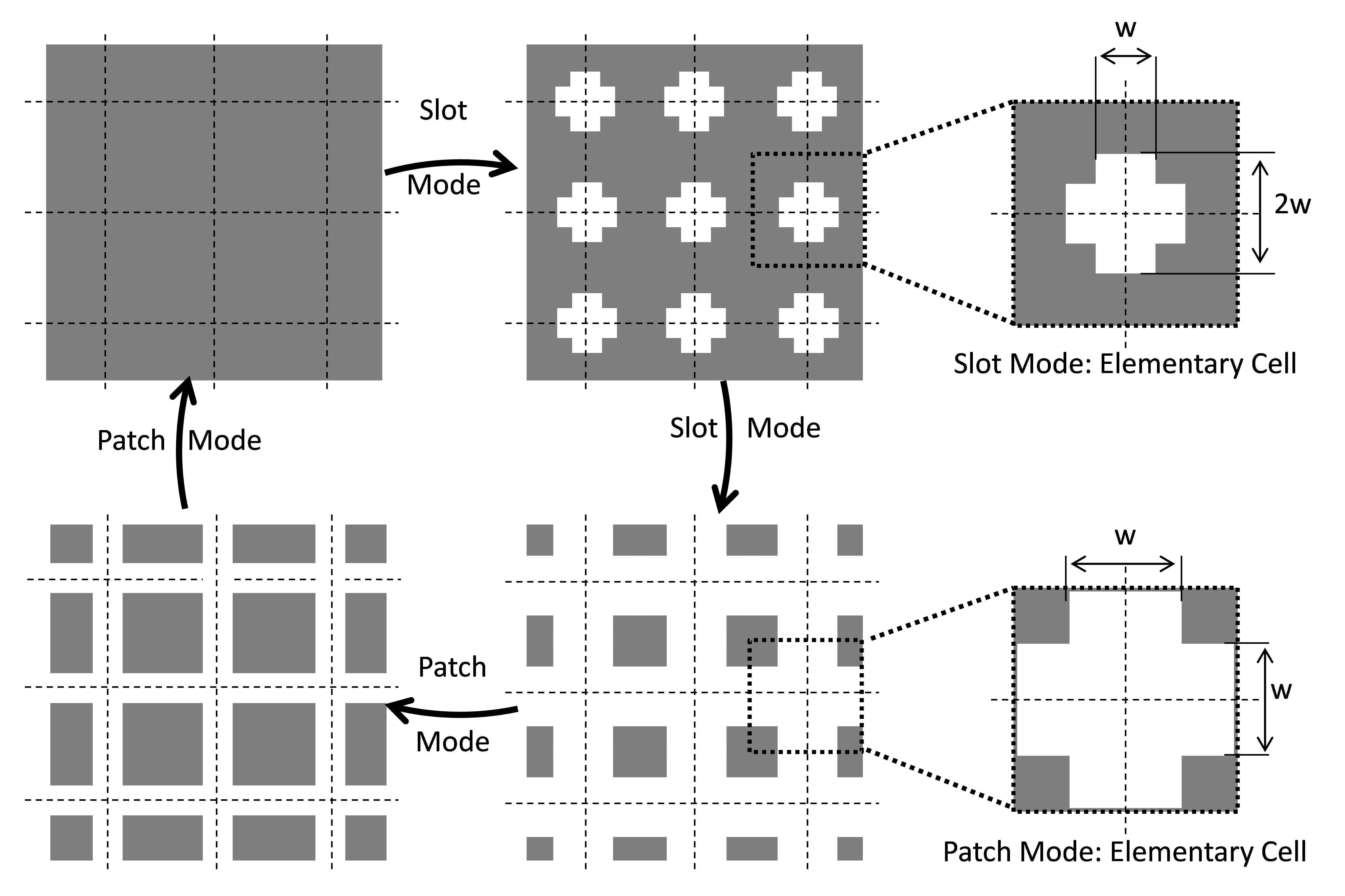 Figure 4. Slot-Patch Phoenix Cell: Rebirth cycle
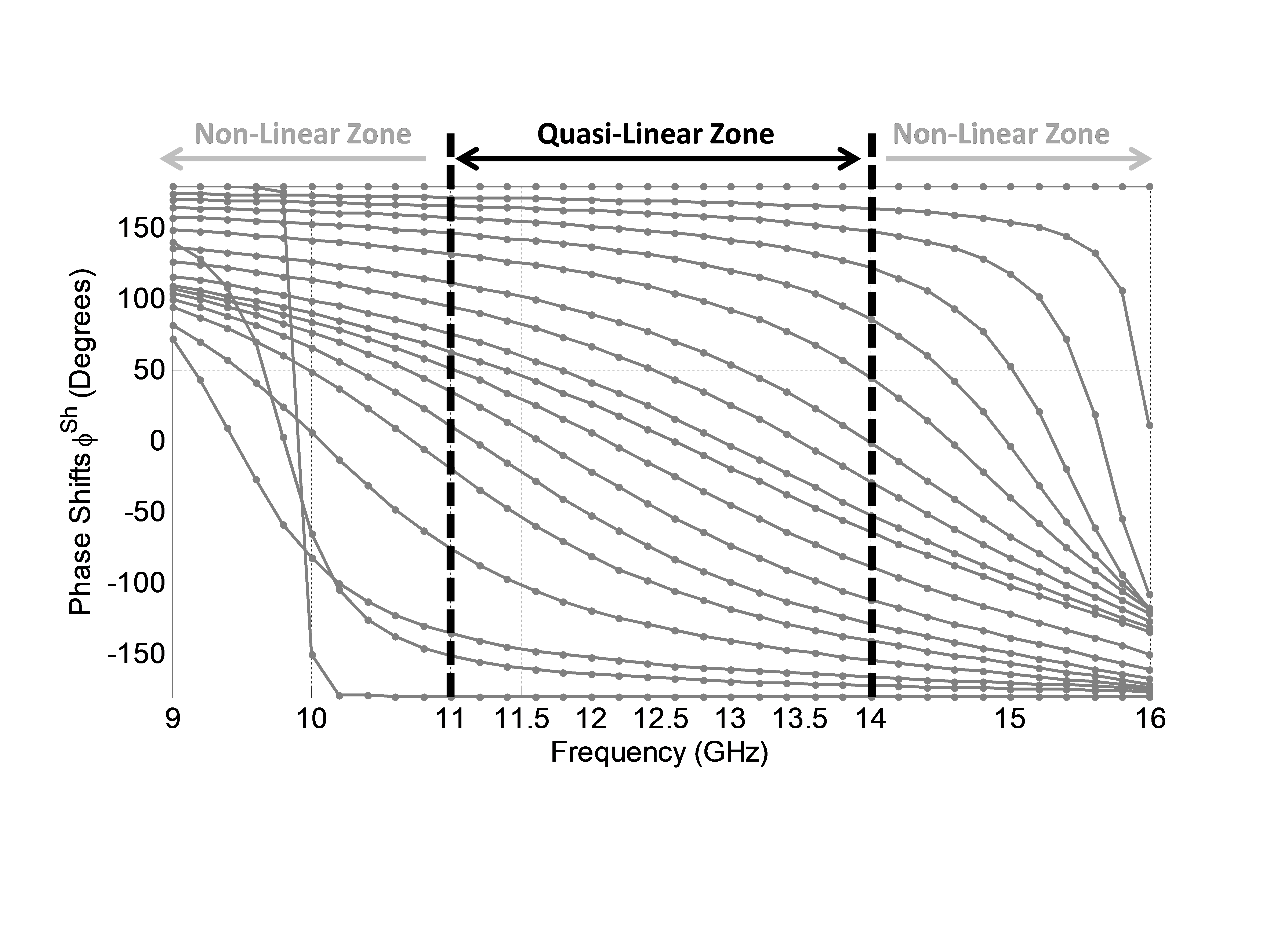 Figure 5. Slot-Patch Phoenix Cell: Phase response.
The first cell, the Slot – Patch Phoenix cell was initially introduced in [8] and its performance was improved in [7]. The cell cycle is illustrated in Figure 4. The initial cell consists of a ground plane providing a 180° phase shift, whatever the frequency. The first mode of operation, or slot mode, is obtained by opening a crossed-shaped slot with variable length and width in the ground plane. For simplicity reasons, the length of the cross is fixed as twice its width. The slot mode ends when the slot arms reach the borders of the cell, thus defining square patches. The operating mode then switches to a patch mode. In this second mode, the length of the pre-opened slot is frozen and only the width of the slot w is decreased. The patch mode ends when the slot vanishes, taking back the cell to its initial geometry and opening the door for a new cycle.
The obtained phase response is presented in Figure 5. At the central frequency, the slot mode provides phase shifts between 0° and 180° while the patch mode completes the remaining phase range between 0° and -180°. The use of complementary modes provides a phase response that is quasi-linear within a 24% bandwidth around 12.5GHz. The maximum dispersion is 53°/GHz. This phase response fits well with the ideal model used to derive (18), although the linearity is not perfect.
5.2. Cell 2: Stub – Patch Phoenix Cell
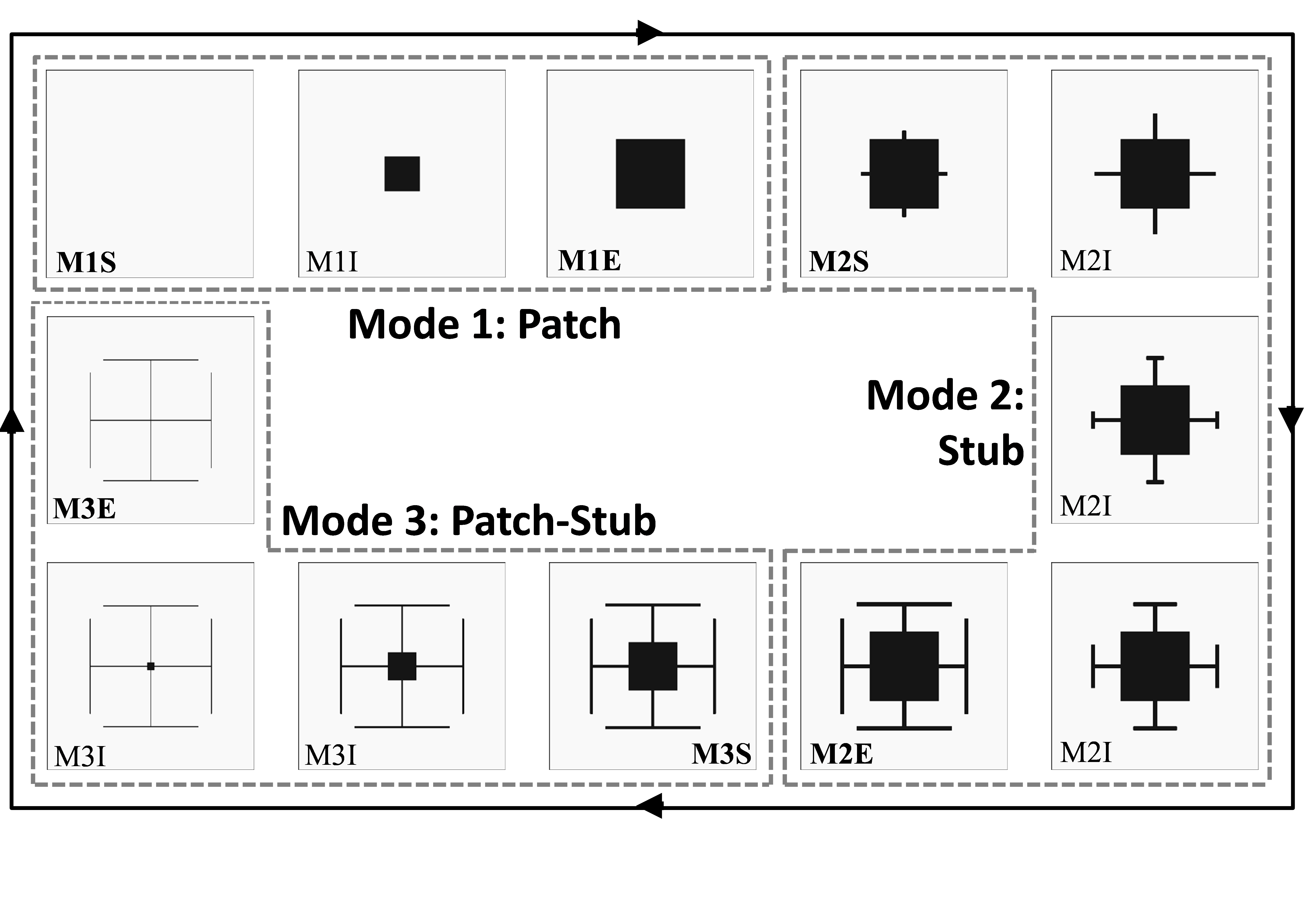 Figure 6. Patch-Stub Phoenix cell: Rebirth cycle (MαS: Mode α’s Start; MαI: Mode α’s Intermediate states; MαE: Mode α’s End).
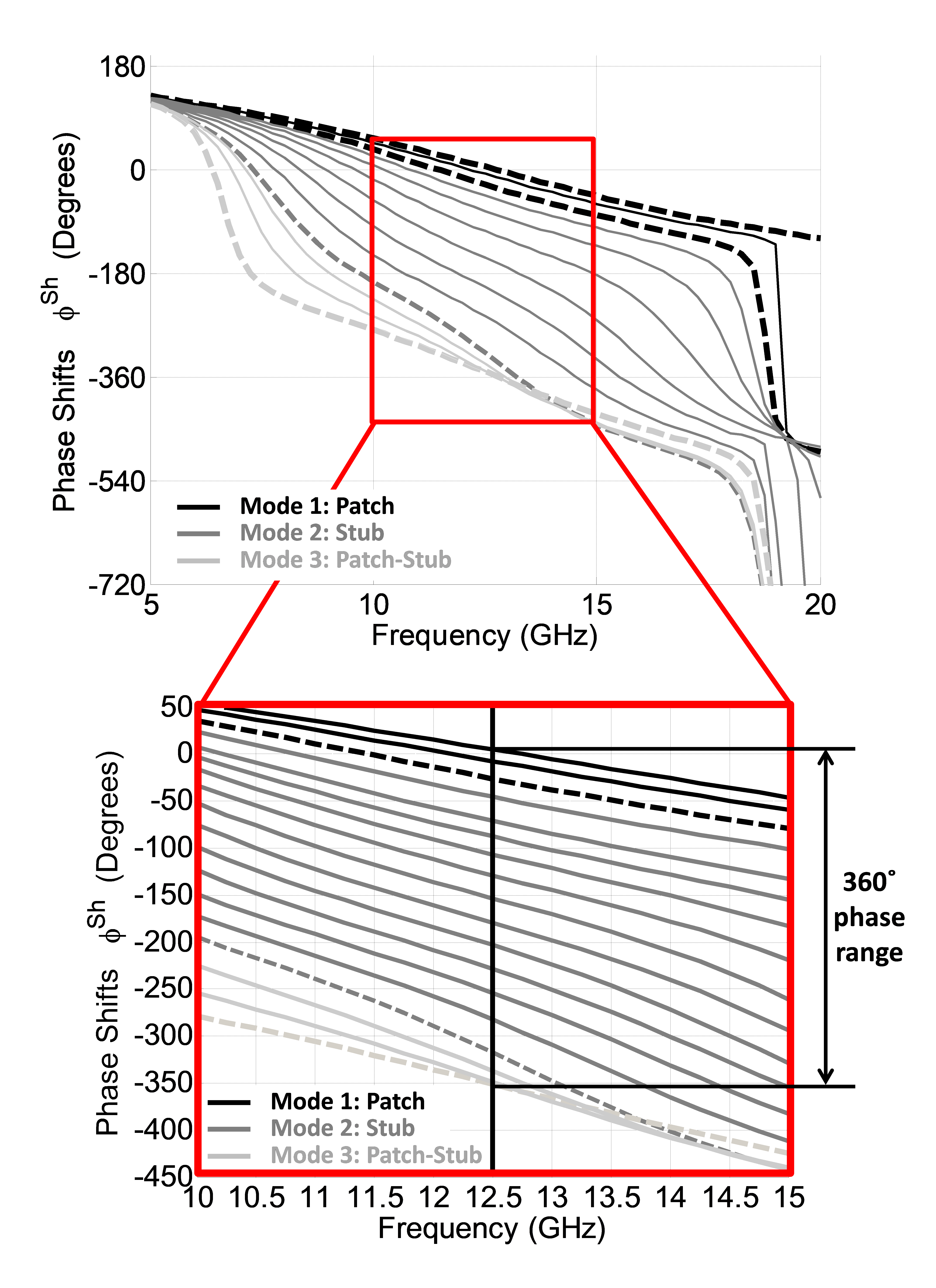 Figure 7. Patch-Stub Phoenix cell: Phase response.
The second cell, the Stub-Patch Phoenix cell was introduced recently in [1]. It improves the bandwidth further due to the three possible operating modes it offers: a patch mode, a stub mode, and a combined patch-stub mode.
As illustrated in Figure 6, the cycle starts with a pure Duroïd substrate backed by a ground plane providing an initial phase shift close to 0° at f0. The first mode of operation, namely the patch mode, is obtained by inserting a square patch at the center of the cell (cf. Figure 6 – Mode 1). The phase shift produced by the cell is controlled by increasing the patch size until it reaches a maximum predefined value.
In mode 2, namely the stub mode, the patch size is frozen to this maximum value and four open-circuited stubs are grown perpendicularly to the patch from the center of its edges (cf. Figure 6 – Mode 2). A T-shape is used for the stubs when the total metal length approaches the limit allowable by the inter-element spacing. In this mode, the phase shift is thus controlled by the length of the stubs.
The mode then switches to mode 3, namely the patch-stub mode, during which the stub-loaded patch shrinks gradually until both patch and stubs disappear completely allowing the cell to rebirth and to start a new cycle (cf. Figure 6 – Mode 3). In this mode, the phase shift is controlled by the shrinking ratio.
The phase response of the suggested cell in all modes is summarized in Figure 7. Dashed curves represent the start/end of a mode (i.e. MαS/MαE) and continuous lines represent intermediate states (i.e. MαI). As can be noticed, a phase range of 360˚ is achieved at f0. Within a frequency band ranging from 10 to 15GHz (40%), the phase response is almost linear. The maximum phase dispersion is obtained at the transition from mode 2 to mode 3 and is equal to 55˚/GHz. The minimum dispersion is obtained at the beginning of mode 1 and is equal to 21˚/GHz. Compared to cell 1, cell 2 exhibits a better linearity of phase response. On the other hand, its minimum dispersion is not zero as required by the previously-used ideal cell model. However, this model still applies if we replace the maximum dispersion by the relative maximum dispersion, defined as the difference between the maximum and minimum dispersions. For cell 2, it is then equal to 34˚/GHz.
5.3. Performance Evaluation and Comparison
The previously-described Phoenix cells are now consecutively used as the radiating element in our test-case RA (F/D=0.8, variable D). The bandwidth is calculated by simulations as in [16] and compared to that given by (18). For this theoretical study, the maximum dispersion Dispmax in (18) is set to 53°/GHz for cell 1 and 34°/GHz for cell 2.
Figure 8 summarizes all theoretical and simulation results. The results show a remarkable agreement between simulation and theoretical curves for a given cell. The slight discrepancy is mainly due to the linearity assumption in the ideal model which is not fully respected by realistic Phoenix cells. It is less than 5% for cell 1 and 3% for cell 2. As expected, a smaller error is obtained for cell 2 as it offers a better linearity of phase response.
Formula (18) is hence a reliable bandwidth estimator, even for realistic phase-shifting cells, provided that they are characterized by a quasi-linear response. As a consequence, it can be advantageously used to define the maximum dispersion allowed for a Phoenix cell to comply with given bandwidth specifications or to predict a Phoenix cell’s performance in a RA configuration.
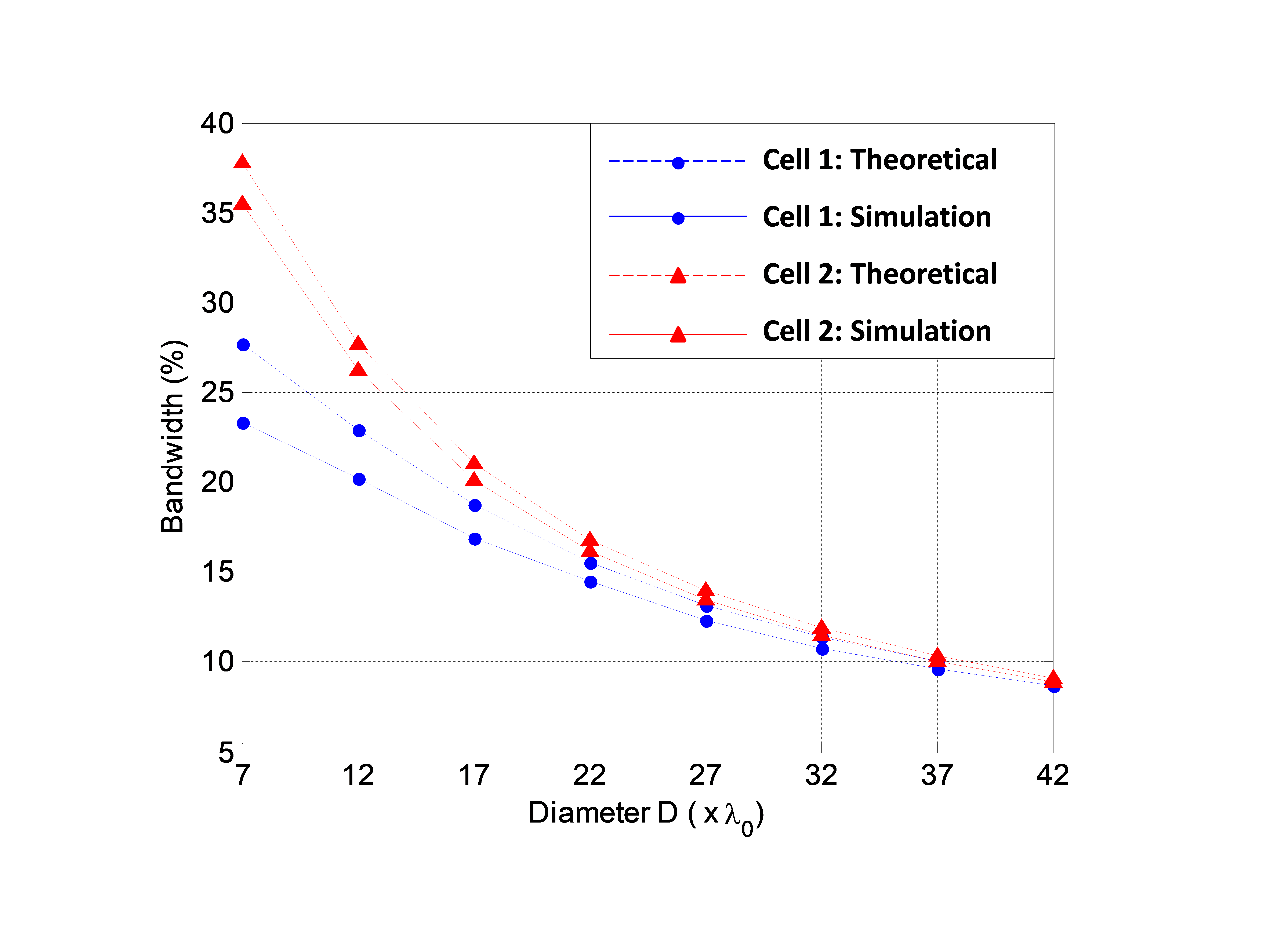 Figure 8. A Realistic study: simulated versus theoretical bandwidth of realistic Phoenix cells (F/D=0.8)
6. Conclusion
Bandwidth limitation of RA results from both the effect of various path delays between cells and source on one side, and intrinsic narrow bandwidth of cells themselves on the other side. The first phenomenon had been significantly investigated in the literature. For the second one, the usual solution relies on the use of broadband cells providing linear and parallel phase states. As this ideal characteristic is never met perfectly, this paper has defined a new approach to assess the effect of imperfection in the phase response of broadband RA cells.
We firstly proposed the standard deviation of phase errors over the array as an efficient criterion to predict RA’s bandwidth when accounting for both its limiting phenomena. This criterion has then been formulated and validated for an ideal cell model with linear but non-parallel phase states. Finally, it has been successfully applied to realistic and novel Phoenix-cells. The suggested approach has thus been demonstrated as a powerful tool to help the designer in the selection of appropriate cells before entering the complex RA optimization process.
- Salti, R. Gillard, “A Single Layer Stub-Patch Phoenix Cell for Large Band Reflectarrays” in 11th European Conference on Antennas and Propagation, Paris, France, 2017. https://doi.org/10.1109/LAWP.2011.2108633
- Moustafa, R. Gillard, F. Peris, R. Loison, H. Legay, E. Girard, “The Phoenix Cell: A New Reflectarray Cell With Large Bandwidth and Rebirth Capabilities” IEEE Antennas and Wireless Propagation Letters, 10, 71-74, 2011. https://doi.org/10.1109/LAWP.2011.2108633
- Deng, F. Xu, F. Yang, M. Li, “Single-Layer Dual-Band Reflectarray Antennas With Wide Frequency Ratios and High Aperture Efficiencies Using Phoenix Elements” IEEE Transactions on Antennas and Propagation, 65(2), 612-622, 2017. https://doi.org/10.1109/TAP.2016.2639023
- Deng, S. Xu, F. Yang, M. Li, “Design of a Low-Cost Single-Layer X/Ku Dual-Band Metal-Only Reflectarray Antenna” IEEE Antennas and Wireless Propagation Letters, 16, 2106 – 2109, 2017. https://doi.org/10.1109/LAWP.2017.2698099
- Wang, Z. Hai Shao, Y. J. Cheng, P. K. Li, “Ka/W Dual-Band Reflectarray Antenna for Dual Linear Polarization” IEEE Antennas and Wireless Propagation Letters, 16, 1301 – 1304, 2017. https://doi.org/10.1109/LAWP.2016.2633289
- Deng, F. Yang, S. Xu, and M. Li, “A low-cost metal-only reflectarray using modified slot-type Phoenix element with 360 phase coverage” IEEE Transactions on Antennas and Propagation, 64(4), 1556-1560, 2016. https://doi.org/10.1109/TAP.2016.2526258
- Salti, R. Gillard, “Slot-Patch Cell with Low Phase Distortion for Large Band Reflectarrays” in Proc. of the Fifth International Conference on Digital Information and Communication Technology and its Applications, Beirut, Lebanon, 2015. https://doi.org/10.1109/DICTAP.2015.7113196
- Makdissy, R. Gillard, E. Fourn, E. Girard, H. Legay, “A patch-slot combination approach for large band reflectarrays” in IEEE European Microwave Conference, Amsterdam, Netherlands, 2012. https://doi.org/10.23919/EuMC.2012.6459392
- E. Bialkowski, K. H. Sayidmarie, “Bandwidth considerations for a microstrip reflectarray” Progress In Electromagnetics Research B, 3, 173–187, 2008. http://dx.doi.org/10.2528/PIERB07120405
- M. Pozar, “Bandwidth of reflectarrays” Electronics Letters, 39(21), 1490-1491, 2003. https://doi.org/10.1049/el:20030990
- Cadoret, A. Laisné, R. Gillard, and H. Legay, “A new reflectarray cell using microstrip patches loaded with slots” Microwave and Optical Technology Letters, 44(3), 270-272, 2005. http://onlinelibrary.wiley.com/enhanced/exportCitation/doi/10.1002/mop.20608
- D. Targonski and D. M. Pozar, “Analysis and design of a microstrip Reflectarray using patches of variable size” in IEEE Symposium on Antennas and Propagation. Seattle, WA, USA, 1994. https://doi.org/10.1109/APS.1994.408184
- Salti, R. Gillard, R. Loison, and L. Le Coq, “A Reflectarray Antenna Based on Multiscale Phase-Shifting Cell Concept,” IEEE Antennas and Wireless Propagation Letters, 8, 363-366, 2009. https://doi.org/10.1109/LAWP.2008.2006073
- Bozzi, S. Germani, and L. Perregrini, “Performance comparison of different element shapes used in printed reflectarrays,” IEEE Antennas and Wireless Propagation Letters, 2, 219–222, 2003. https://doi.org/10.1109/LAWP.2003.819687
- Kai Zhang, Yangyu Fan, Jiadong Xu, Chen Qu, “Design of broadband, low cost single layer reflectarray using phoenix cell,” in TENCON conference, Xi’an, China, 2013. https://doi.org/10.1109/TENCON.2013.6718981
- Salti, E. Fourn, R. Gillard, “Minimization of MEMS breakdowns effects on the radiation of a MEMS based reconfigurable reflectarray,” IEEE Transactions on Antennas and Propagation, 58(7), 2010. https://doi.org/10.1109/TAP.2010.2048861