Parametric Study of Micro Strip Patch Antenna Using Different Feeding Techniques for Wireless and Medical Applications

Adv. Sci. Technol. Eng. Syst. J. 3(1), 310–316 (2025);
 DOI: 10.25046/aj030137
Due to the increasing bandwidth requirement of modern wireless communication systems, developing antenna having wider bandwidth have been receiving significant attention in the recent years. In this paper, a comparative analysis of the contacting feed (micro strip line and coaxial probe) and non-contacting feed mechanism (both Aperture Coupling and Proximity Coupling) in micro strip patch antenna has been done. In case of contacting feed, RF power is fed directly to the radiating patch using a connecting element such as a micro strip line whereas in case of non-contacting feeds, electromagnetic field coupling is done to transfer power between the micro strip line and the radiating patch. As per the latest research, ultra wide band technology is used in the frequency range from 3 GHz to 10 GHz. We have analyzed and compared the return loss and corresponding bandwidth of these four types of antenna at 5.853GHz so that this antenna may be used in medical as well as wireless applications.
1. Introduction
Micro strip patch antennas are considered as an indispensable tool in today’s research oriented activities. The design and manufacturing cost of micro strip antenna is very cheap because of its 2D geometrical structure [1]. The patch antenna is a popular resonant antenna used for microwave wireless communications that require semispherical coverage. Some patch antennas avoid using a dielectric substrate and suspend a metal patch in the air above a ground plane using dielectric spacers; the resulting structure provides increased bandwidth. With an increase in frequency, the input impedance moves to the clockwise direction on the Smith chart [2]. Wireless and Medical applications requires small, low-cost, low profile antennas which has Omni directional radiation pattern in horizontal planes. Micro Strip patch antenna meets all requirements. Figure 1 shows a typical structure of a rectangular micro strip antenna.
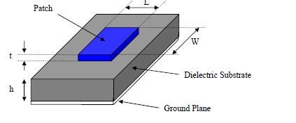 Fig 1: Micro Strip Patch Antenna
2. Feeding Mechanism
Suitable feeding technique plays an important role for antenna efficiency and better impedance matching. The feeding techniques used in the micro strip antenna are given below:
2.1. Contacting Feed:
In this method, contacting element such as micro strip line or coaxial line is used to help the patch so that it can be fed directly to RF power. The most commonly used contacting feed methods are [3]:
- Line Feed
- Co-axial probe Feed
· Micro Strip Line Feed:
Micro strip line feed is one of the easier methods to fabricate as it is just a conducting strip connecting to the patch and therefore can be considered as extension of patch.[3-4] It is simple to model and easy to match by controlling the inset position. However the disadvantage of this method is that as substrate thickness increases, surface wave and spurious feed radiation increases which limit the bandwidth.
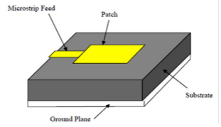 Fig 2: Micro strip Line feeding
· Coaxial Probe Feed:
Coaxial feeding is feeding method in which that the inner conductor of the coaxial is attached to the radiation patch of the antenna while the outer conductor is connected to the ground plane.
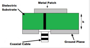 Fig 3: Coaxial Probe feeding
2.2. Non-Contacting Feed:
In this method, the RF power is transferred to the path from the feed line through electromagnetic coupling instead of feeding directly. The commonly used non-contacting feed methods are:
- Aperture Coupled feed
- Proximity Coupled feed
· Aperture Coupling Feed:
In the aperture coupled feed technique, the radiating patch and the micro strip feed line are separated by the ground plane. Coupling between the patch and the feed line is made through a slot or an aperture in the ground plane.
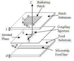 Fig 4: Aperture Coupled feeding
- Proximity Coupling Feed:
In this method, two dielectric substrates are placed such that the feed line lies in between the two substrates and the radiating patch is placed at the top of the upper substrate.
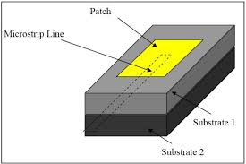 Fig 5: Proximity Coupled feeding
The two dielectric substrates can be selected independently to optimize both micro strip guided waves and patch radiating waves. The ranges of operating thickness of the substrate have a big effect on the resonant frequency and bandwidth of the antenna. Bandwidth of the micro strip antenna will increase with increasing substrate thickness. However, certain limits must not be exceeded, and otherwise the antenna will stop resonating. Therefore, [4], the measures for selecting a substrate may include the following:
(a) Surface-wave excitation.
(b) Dispersion of the dielectric constant and loss tangent of the substrate.
(c) Anisotropy in the substrate.
(d) Cost Effective
3. Study of Antenna Designing Parameters
There are three essential parameters for design of a rectangular micro strip Patch Antenna. Firstly, the resonant frequency (f0) of the antenna must be selected appropriately. The frequency range for ultra wide band applications is from 3.1GHz to 10.6 GHz and the design antenna must be able to operate within this frequency range.
The second important parameter of good antenna design is dielectric substrate ( r). A thick dielectric substrate having low dielectric constant is desirable. This provides better efficiency, larger bandwidth and better radiation. FR-4 Epoxy which has a dielectric constant of 4.4 for lower substrate and RT –Duroid for upper substrate having dielectric constant of 2.2 and loss tangent equal to 0.009 can be used for new antenna design [5-6]. The other antenna parameters to be considered for design are length of the patch L, width W, height of dielectric substrate h and Loss Tangent. The patch length is considered around Lg/2 (Lg – Length of the ground plane) to initiate the radiation. The antenna is typically fed at the diverging edge on the dimension W because it offers sensible Polarization. The antenna parameters can be calculated by the transmission line method as exemplified below [7]:
3.1 Width of the Patch (mm):
Having specified the height of the patch antenna, the first step in the design procedure is to determine the width of the patch. This can be calculated using the following equation:
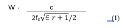 Where,
c = Speed of light in free-space (3 ×10⁸ m/s)
f0= Resonating frequency
3.2 Calculation of Effective Dielectric Constant (ϵreff ):
This is calculated using the following equation:
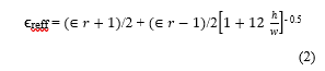 Where, h= height of the patch (mm)
W= width of the patch (mm)
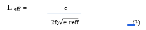
3.3 Calculation of Effective Length (Leff):
This is calculated using the following equation:
 3.4 Calculation of Length Extension ( L):
The length extension is calculated using the following equation;
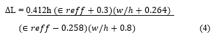 Where,
L= Patch length extension (mm)
h = height (mm)
W = width of the patch (mm)
3.5 Calculation of Actual Length:
The actual length of the patch antenna is calculated using the following equation;
 4. Design and Simulation of Micro Strip Patch Antenna for Different Feeding Methods
4.1. Micro Strip Line Feed:
The antenna is designed at resonating frequency 5.853 GHz of WLAN. It is designed using transmission line model [8]. This section describes the design of rectangular patch antenna satisfying the given specifications:
Table 1: Design specification of Aperture Coupled Patch
| Frequency | 5.853 GHz |
| Antenna Dimension | 29mm x 41mm |
| Dielectric Constant (RT Duroid) | 2.2 |
 Fig 6: Designed Structures on CST Studio
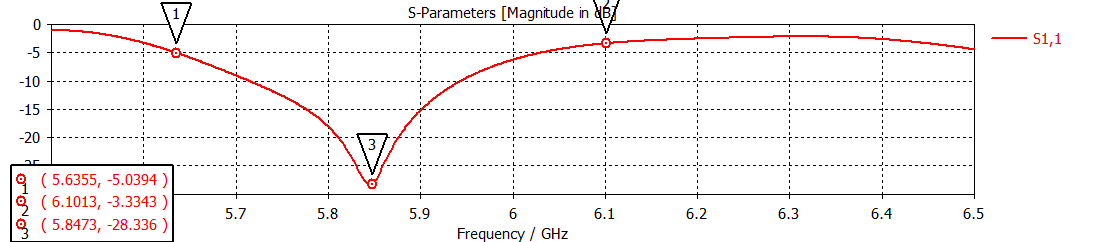 Fig 7: Return Loss S11 of simulated antenna at 5.853 GHz
Return Loss:
Fig 7 shows the S11 parameters (Return Loss = – 28dB) for the proposed antenna. The designed antenna resonates at 5.853 GHz.
Smith Chart:
The Smith Chart plot (Fig. 8) represents that how the antenna impedance varies with frequency and gives impedance of 50.4 ohms. For proper matching, the locus must be large so that it connects with the center point of the smith chart.
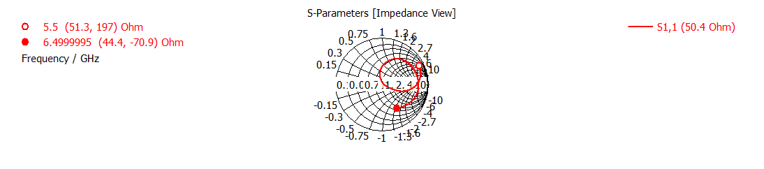 Fig 8: Smith Chart of simulated antenna at 5.853 GHz
Calculation of VSWR:
Fig. 9 shows the VSWR plot against frequency that numerically describes how well the antenna matches with the transmission line it is connected to.
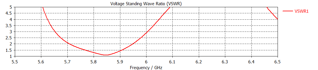 Fig 9: VSWR of simulated antenna at 5.853 GHz
4.2. Coaxial Probe Feeding:
The antenna is designed at resonating frequency 5.853 GHz of WLAN. It is designed using transmission line model. This section describes the design of rectangular patch antenna satisfying the given specifications:
Return Loss:
Fig 11 shows the S11 parameters (Return Loss = -37dB) for the proposed antenna. The designed antenna resonates at 5.853 GHz.
Table 2: Design specification of Proximity Coupled Patch
| Frequency | 5.853 GHz |
| Antenna Dimension | 29mm x 41mm |
| Dielectric Constant (RT Duroid) | 2.2 |
 Fig 10: Designed Structure on CST Studio
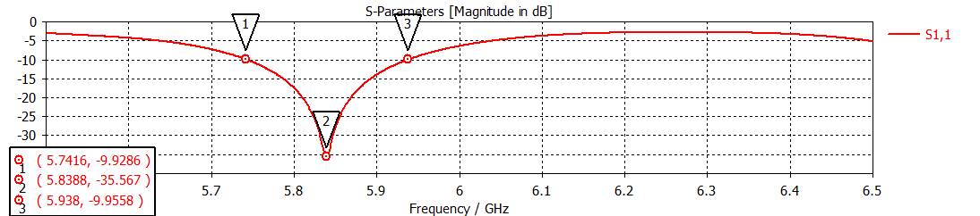 Fig 11: Return Loss S11 of simulated antenna at 5.853 GHz
Smith Chart:
The Smith Chart plot (Fig. 12) represents that how the antenna impedance varies with frequency and gives impedance of 50.21 ohms. For proper matching, the locus must be large enough that it passes through the center of the smith chart.
As it can be seen from Fig. 12, the circle cuts the resistive part at 0.5021, thus matching at 50.21 ohm.
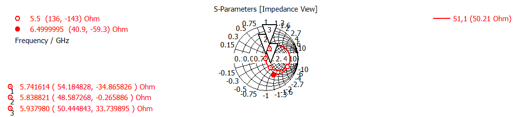 Fig 12: Smith Chart of simulated antenna at 5.853 GHz
Calculation of VSWR:
Fig. 13 shows the VSWR plot against frequency that numerically describes how well the antenna matches with the transmission line it is connected to.
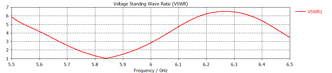 Fig 13: VSWR of simulated antenna at 5.853 GHz
4.3. Aperture Coupled Feeding:
The antenna is designed at resonating frequency 5.853 GHz of WLAN. It is designed using transmission line model. This section describes the design of rectangular patch antenna satisfying the given specifications:
Table 3: Design specification of Aperture Coupled Patch
| Frequency | 5.853 GHz |
| Antenna Dimension | 29mm x 41mm |
| Lower Dielectric Constant (FR4) | 4.4 |
| Upper Dielectric Constant (RT Duroid) | 2.2 |
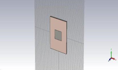 Fig 14: Designed Structures on CST Studio
Return Loss:
Fig 15 shows the S11 parameters (Return Loss = – 33dB) for the proposed antenna. The designed antenna resonates at 5.853 GHz.
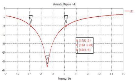 Fig 15: Return Loss S11 of simulated antenna at 5.853 GHz
Smith Chart:
The Smith Chart plot (Fig. 16) represents that how the antenna impedance varies with frequency and gives impedance of 49.93 ohms. For proper matching, the locus must be large so that it connects with the center point of the smith chart.
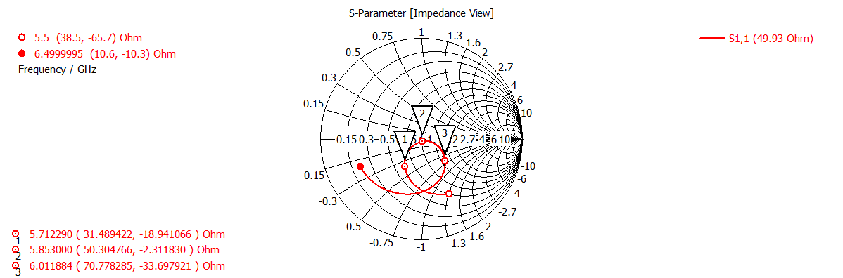 Fig 16: Smith Chart of simulated antenna at 5.853 GHz
Calculation of VSWR:
Fig. 17 shows the VSWR plot against frequency that numerically describes how well the antenna matches with the transmission line it is connected to.
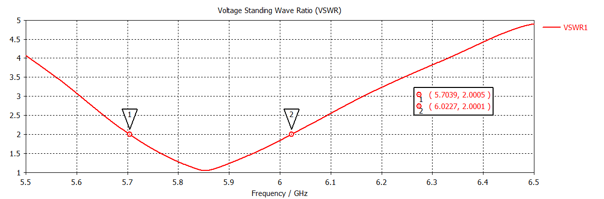 Fig 17: VSWR of simulated antenna at 5.853 GHz
4.4. Proximity Coupled feeding:
The antenna is designed at resonating frequency 5.853 GHz of WLAN. It is designed using transmission line model. This section describes the design of rectangular patch antenna satisfying the given specifications:
Table 4: Design specification of Proximity Coupled Patch
| Frequency | 5.853 GHz |
| Antenna Dimension | 29mm x 41mm |
| Lower Dielectric Constant (FR4) | 4.4 |
| Upper Dielectric Constant (RT Duroid) | 2.2 |
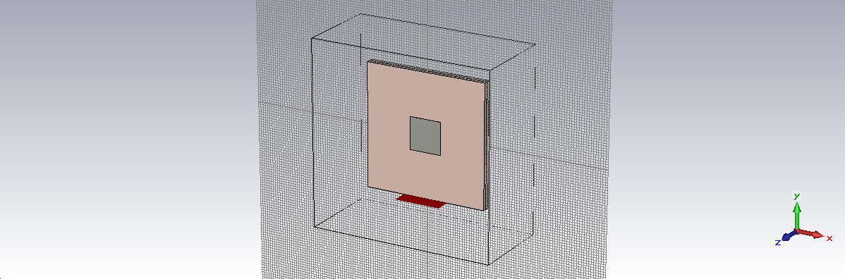 Fig 18: Designed Structure on CST Studio
Return Loss:
Fig 19 shows the S11 parameters (Return Loss = -47dB) for the proposed antenna. The designed antenna resonates at 5.853 GHz. More negative the return loss, higher the directivity and gain of the proposed antenna in particular direction.
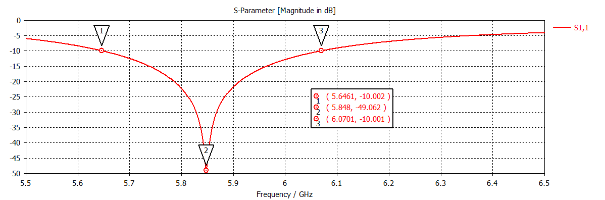 Fig 19: Return Loss S11 of simulated antenna at 5.853 GHz
1) Smith Chart:
The Smith Chart plot (Fig. 19) represents that how the antenna impedance varies with frequency and gives impedance of 49.97 ohms. For proper matching, the locus must be large enough that it passes through the center of the smith chart.
As it can be seen from Fig. 19, the circle cuts the resistive part at 0.4997, thus matching at 49.97 ohm.
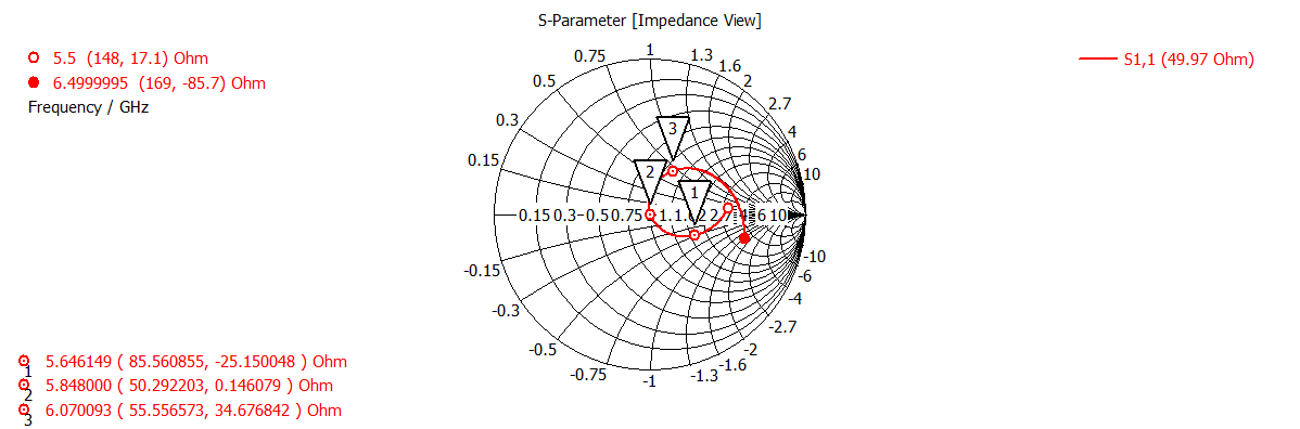 Fig 6.3: Smith Chart of simulated antenna at 5.853 GHz
3) Calculation of VSWR:
Fig 20 shows the VSWR plot against frequency that numerically describes how well the antenna matches with the transmission line it is connected to.
5. Comparative Study of Important Parameters
|
Characteristics |
Line |
Coaxial |
Aperture |
Proximity |
| Return Loss (S11) (dB) |
-28 |
-37 |
-33 |
-47 |
| Bandwidth (MHz) |
250 |
210 |
320 |
475 |
| VSWR |
1.08 |
1.13 |
1.04 |
1.16 |
| Impedance
(ohm) |
50.4 |
50.21 |
49.93 |
49.97 |
Table E : Comparison of Different Feeding Techniques
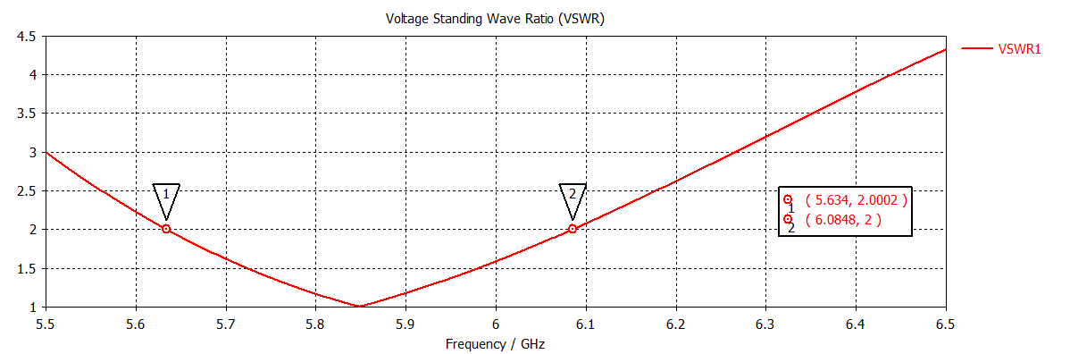 Fig 20: VSWR of simulated antenna at 5.853 GHz
Conclusion
Finally, the optimum result of all four feeding techniques of rectangular patch antenna on FR4 and RT-duroid substrate for Wi-max applications has been investigated. A comparison is made between feeding techniques [9-10] in terms of bandwidth, return loss, VSWR and impedance matching. So, we can see that selection of the feeding technique for a micro strip patch antenna is an important decision because it affects the bandwidth and other parameters also. A micro strip patch antenna excited by different excitation techniques gives different bandwidth, different gain, different efficiency etc. The maximum bandwidth can be achieved by proximity coupling. Proximity coupling gives the best impedance matching and radiation efficiency. Coaxial feeding technique gives the least bandwidth. We can also conclude that by changing the feed point where matching is perfect, the high return loss can be achieved at the resonant frequency. Various micro strip patch antennas with each different feeding technique are presented. The various parameters like return loss, smith chart, and VSWR are plotted for each antenna.
Conflict of Interest
The authors declare no conflict of interest.
Future Scope of Work
The designed patch antenna is intended for wireless applications. This paper mainly deals with the simulation of its characteristics for different feeding techniques which must have to be verified with the fabricated one. The size of this antenna ultimately restricts its usage mainly in biotelemetry in the field of medical applications. So, to extend its usage as an implantable one, its reduced size with similar characteristics has to be investigated. Using bio-compatible ceramic resins instead of conventional one to reduce its size has a great future scope of this work. Also, this design has to be compared with other miniaturized antenna techniques to ensure proper selection of implantable body antenna.
Acknowledgment
The authors of this paper would like to thank University Grant Commission (UGC) for giving the opportunity to work in Modern Biology Group B: “Image and Imaging” under UPE-II. We also acknowledge all the contribution of corresponding IEEE authors and most importantly the publishers of related books and journals which gave immense support and inspiration in preparing this manuscript. Above all, the extreme mental support and source of inspiration from all the family members and friends are widely acknowledged.
- A.Balanis, Antenna Theory Analysis And Design,Second Edition,John Wiley & Sons. Ramesh Garg,Prakash Bhartie,inder Bahl,Apisak Illipiboon ,Microstrip Antenna Design Handbook, pp.1-68,253-316 Artec House Inc.Norwood,MA
- Ramesh Garg,Prakash Bhartie,inder Bahl,Apisak Illipiboon, Microstrip Antenna Design Handbook,pp.168,253-316 Artec House Inc.Norwood.
- Amit kumar Jaspreet kaur Rajinder singh,(2013), Performance analysis of different feeding technique,vol 3 issue 3.
- Praveen Kumar, K. Sanjeeva Rao, T. Sumanth, N. Mohana Rao, R. Anil Kumar, Y.Harish,(2013) Effect of Feeding Techniques on the Radiation Characteristics of Patch Antenna: Design and Analysis International Journal of Advanced Research in Computer and Communication Engineering Vol. 2, Issue 2.
- Devan Bhalla And Krishan Bansal,(2013) Design of a Rectangular Microstrip Patch Antenna Using Inset Feed Technique IOSR Journal of Electronics and Communication Engineering (IOSR-JECE) e-ISSN: 2278-2834,p- ISSN: 22788735. Volume 7, Issue 4 PP 08-1
- Brajlata Chauhan, Sandeep vijay, S C Gupta(2013) Comparative analysis of Microstrip Patch Antenna using different substrate and observe effect of changing parameter at 5.4 GHz, Conference on Advances in Communication and Control Systems
- Fouzi Harrou, Abdelwahab Tassadit (2010), Analysis and Synthesis of Rectangular Microstrip Antenna ,Journal of Modelling and Simulation of Systems vol 1Issue 1 pp. 34-39.
- Rajesh Kumar Vishwakarma, Sanjay Tiwari,(2011) Aperture Coupled Microstrip Antenna for Dual-Band ,Wireless Engineering and Technology vol 2,93-101
- John R. Ojha Marc Peters and Igor Mini,(2010) Patch Antennas and Microstrip Lines, microwave and millimeter wavetechnologies modern uwb antennas and equipment ISBN: 978-953-7619-67-1.
- Hemant Kumar Varshney, Mukesh Kumar, A.K.Jaiswal, Rohini Saxena and Anil Kumar (2014) Design Characterization of Rectangular Microstrip Patch Antenna for Wi-Fi Application, Vol.4, No.2, E-ISSN 2277 – 4106, P-ISSN 2347 – 5161.