Leaf-shaped solar cell antenna for Energy Harvesting and RF Transmission in ku-band

Adv. Sci. Technol. Eng. Syst. J. 2(6), 130–135 (2017);
 DOI: 10.25046/aj020616
In this paper, a hybrid system solar cell antenna was studied. Our contribution lies in the combination of both optical and radio-frequency signals in a solar cell antenna. Hence, we propose a new method to merge antenna and solar cell. The leaf- shaped patch solar cell antenna was dedicated at a time to the energy harvesting and the RF transmission. A performance analysis of the solar cell antenna was conducted using Advanced Design System (ADS) software. Simulation results showed a resonance at a frequency of 15.77 GHz with an effective return loss of -27.62dB and a gain of 5.77dBi.
1. Introduction
Solar energy was considered as one of the most renewable energy resources that could fill the shortage of energy needs. In fact, human beings used the solar energy to produce electricity. Although the photovoltaic (PV) cell was first employed to produce it, its efficiency remained limited [1]. Solar energy has become an attractive alternative for powering autonomous communication systems. Many communication systems, such as standalone systems like environmental monitoring system, vehicular communication and satellite systems [2] require electric energy for their operation and use. Solar powered communication systems have received considerable attention due to their ability to operate without the necessity of being connected to an electricity grid. This has become a significant challenge when it comes to powering communication systems in remote places where the electricity grid is not available. In order to address this challenge, the use of photovoltaic in communication systems has recently been the subject of many researches. The photovoltaic systems of power generation when combined with communication systems can provide compact and reliable autonomous communication systems, which can be used for many applications.
Traditionally, telecommunication antennas and solar cells do not mix. They must operate independently so as not to interfere. They compete for the available space on mobile and standalone systems which are generally limited in size. Furthermore they may be bulky and expensive and they limit the capabilities of product designs. In space applications for instance, both solar panels and communication system are major contributors to the overall size and weight of the satellites and combining these two systems could save real estate and cost. In urban areas, wireless communication infrastructures could be integrated into solar panels. Finally the integration of antennas and solar cell panels can be essential for the transportability of emergency autonomous communication stations [3-4] and [5-6].
In this paper, we describe the solar cell antenna in the second section; we detail the proposed approach as well as the effects of optical transparency on the antenna parameters. In the third section we explain the proposed solar cell antenna structure by giving a model of the mesh patch with optimized geometry. The simulations results of the solar cell antenna are presented. A solar cell antenna array has also been studied in this section by giving their parameters. The solar cell antenna equivalent circuit as well as the RF / DC decoupling circuit have been studied in order to eliminate the influence of the RF signal on the DC signal and to show that this hybrid system will be both for the recovery of a solar cell, energy and RF transmission. Finally, we conclude the paper.
2. Solar cell antenna
2.1. Approach
Several attempts to integrate solar cells with patch antennas have been studied, but they did not pay attention to the antenna patch when it is placed above a solar cell. To remedy the drawbacks, especially of limited surface area, encountered during the integration of patch antenna with a photovoltaic cell, we propose here new types of antennas based on optically transparent photovoltaic cells with mesh patches.
Optically transparent mesh patch antennas are antennas that have a certain level of optical transparency. These transparent antennas, for example, are potentially suitable for integration with solar cells for small satellites. Traditional patch antennas used on small satellites compete with solar cells for the surface. However, a mesh patch antenna can be placed directly on the solar cells and solve the surface limitation problem. For such integration, a high optical transparency of the patch antenna is required from the solar cells point of view, since solar cells require sufficient sunlight to generate adequate electrical power. On the other hand, the antenna must have at least acceptable electrical properties at the same time so that it can radiate correctly and efficiently [7-8] and [9-11].
The hybrid system studied in this paper was devoted at a time to the energy harvesting and the RF transmission for satellite communication. This structure was made of a photovoltaic cell in which the front grid was designed to have a miniature antenna suited to the band transmission and to minimize the power loss of the cell devoted to energy conversion. The received electrical energy was used to operate the complete system.
2.2. Optical transparency effects on the antenna parameters
The openings in the conductor make it possible to pass the light while the mesh can still be conceived as an efficient radiator. Mesh patch antennas, compared to their solid counterparts, have a higher surface resistance due to much lower conductor coverage. Consequently, it is normal, when the optical transparency increases, to have a low performance of the antenna.
The antenna optical transparency is given most often by the ratio of the mesh patch surface to the patch total area (eq.1).
 It has been demonstrated that, when the line width is fixed, we notice that during the patch transparency increase the frequency of resonance decreases. Since t the patch physical length is the main determinant of the resonance frequency as noted by Clasen [7], the increase in transparency introduces the possibility of minimizing the antenna design. Using the mesh patch increases the fringing fields; therefore, increase the antenna electrical length [12]. Also from Figure 1 one is able to see that increasing the transparency decreases the bandwidth. Bandwidth is defined by the following equation:
 With fh the highest frequency at which the voltage standing wave ratio (VSWR) is below 2, fl the lowest frequency at which the VSWR is below 2, and fr is the frequency of the minimum VSWR.
Also as seen in Figures.2, 3 and 4, the increase in transparency decreases the antenna efficiency, gain and directivity.
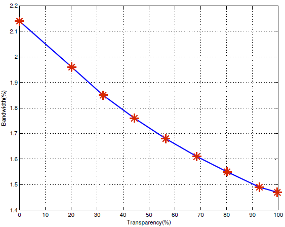 Figure 1: Bandwidth in terms of transparency
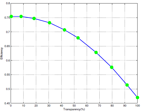 Figure 2: Efficiency in terms of transparency
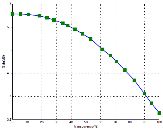 Figure 3: Gain in terms of transparency
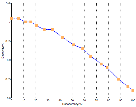 Figure 4: Directivity in terms of transparency
2.3. Effect of the line width
The study of optically transparent antennas is based essentially on the optimization of the mesh patch dimensions. In this paper, antennas with an optical transparency of 70%, 80% and 90% are generated. Each transparency depended of the line width and the number of mesh lines. Simulation results present the efficiency of the mesh antenna as a function of the line width for each transparency is plotted in figure 5. We interpret that for a given transparency, efficiency of a mesh antenna can be improved by refining the line width. From fabrication standpoint of view, the line width realization of 0.1 mm or more is simple. The efficiency and transparency are adequate for this hybrid system of solar cell antenna for satellite and terrestrial communications. From the simulation results (see Figure 5), we conclude that with a line width of 0.1 mm, it is possible to achieve more than 60% efficiency with an antenna of 90% transparency, 63% efficiency with an antenna of 80% transparency and 67% efficiency with an antenna of 70% transparency.
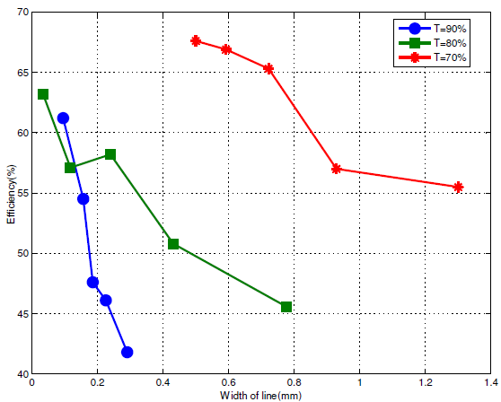 Figure 5: Efficiency in terms of width of line
Efficiency is inversely proportional with optical transparency, this is true because traditional patch antennas are more efficient but when they are integrated with solar cells they screen these and can reduce the collected electrical power. Our method allows us to propose a hybrid solar cell antenna system for energy harvesting and RF transmission for satellite and terrestrial communications.
3. Simulations results and discussions
3.1. Structure of solar cell antenna
We propose a solar cell antenna with mesh patch. A mathematical model that we have already studied to minimize the power losses of the solar cell antenna and improve the conversion efficiency as a solar cell [13-14]. Optimization of the maximum electrical power collected as a function of finger width was determined. The optimal width Wf has been used for the mesh patch design or front face collection grid.
Improving the performance of a solar cell depends not only on the materials and structure but also on the design of the metal grid front face.
With this mesh patch structure two types of waves can exist. The optical waves that will be absorbed by the silicon (semiconductor) and the RF waves that will be collected by the mesh patch metal whose width of fingers Wf is optimized. The structure designed was a solar cell antenna printed on a multi-layered substrate Figure 6.
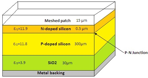 Figure 6: Multi-layered substrate of solar cell antenna
The silicon on an insulating layer SiO2 confers to the components that are realized, a higher operating frequency, an ability to operate at low voltage and low power consumption and an insensitivity to the effects of ionizing radiation. When using a thin-film substrate we observe that the simulations are complex and time consuming. The meshed patch of solar cell antenna proposed is given in Figure 7. The dimensions of the proposed patch of solar cell antenna are given in the following table (Table 1).
Table 1: Dimensions of solar cell antenna
| Parameters | Values |
| Width of busbars | Wb=0.5mm |
| Width of finger | Wf=60 µm |
| Length of feedline | L= 9.1 mm |
| Width of feedline | W=0.235 mm |
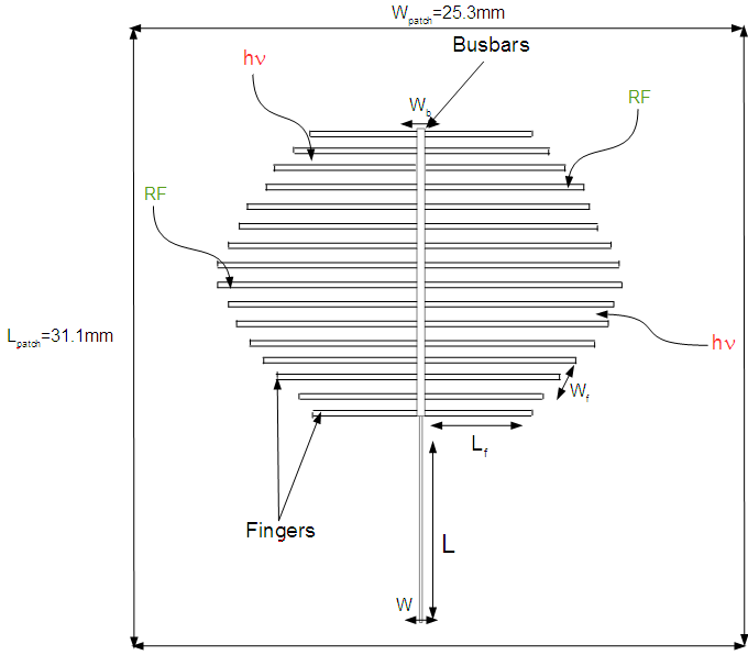 Figure 7: Meshed patch of solar cell antenna proposed
This antenna was excited by a microstrip line of characteristic impedance equal to 50 Ω. In this paper, the transparency of a patch is defined by the percentage of see-though area on the patch as shown below (see equation 3):
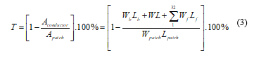 where Wf is the mesh line width, Lf length of each mesh line, Wb is the busbars line width, Lb the busbars length, W is the InsetFeed width, L is the InsetFeed length, Wpatch is the patch width and Lpatch is the patch length (see Figure7).
3.2. Antenna Parameters
As an antenna, the electromagnetic performances of the solar cell antenna were simulated by using the ADS software. The simulated S11 parameter was presented in Figure 8. An antenna should be perfect radiator, rather than perfect absorber. The amount of radiated power returned back through the port can be calculated for finding return loss at that resonating frequency. For the resonant frequencies the return loss should be less than -10dB i.e. S11<-10 dB. Simulation results show that the designed antenna can be used as a frequency antenna with an effective return loss of -27.62dB at 15.77GHz. To the normal scale $S11=10-2.762, ie only 0.17% of the emitted power will be reflected as well as the impedance Za=49.82 Ω which confirms the adaptation of the antenna. The adaptation of our antenna is substantiated by the return loss low value S11. Similarly, its operation can be assessed by the VSWR curve which is another performance measurement parameter at the input. It indicates the signal reflection due to a mismatch between the impedance of the antenna and that of the source. The reflected signal leads to the appearance of the standing wave voltage in the feed line which, in turn, destroys the reliability of the antenna. The ideal value of VSWR is 1 which means that 100% of the delivered power is accepted (no reflection). But, practically speaking, it is tolerable up to 2 [15]. The VSWR obtained for this antenna equal to 1.0036.
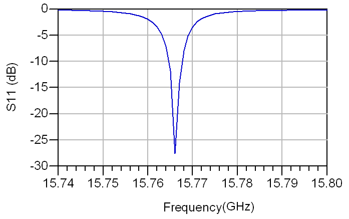 Figure 8: Reflection coefficient S11
The radiation of our antenna is gathered in the main lobes which have a wide beam width at -3 dB and whose amplitude is much higher than that of the side lobes. This reflects a very directive radiation by offering a total directivity equal to 7.26 dB at 15.77 GHz. The radiation pattern of this antenna at a frequency of 15.77GHz is shown in Figure 9. The polarization of the radiated field was linear.
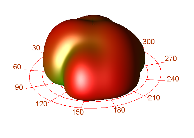 Figure.9: Radiation pattern
When designing an antenna, the gain must be taken into consideration as it is an important metric. The good values of S11 and VSWR are not enough to confirm a good radiation. Antenna gain describes how much power is transmitted in the direction of peak radiation to that of an isotropic source. The gain of this antenna was 5.77dBi.
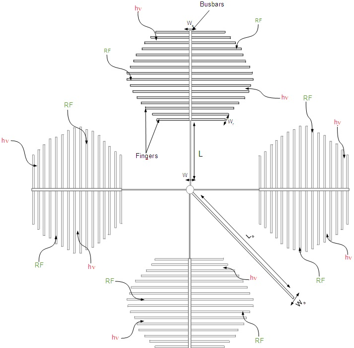 Figure 10: Array of antennas
3.3. Array of antennas
In order to increase the gain, we proposed an array of antennas shown in Figure 10. Simulation results of S11 parameter and radiation pattern are given, respectively, in Figures 11 and 12.
This array of antennas was excited by a microstrip line of La=16.82 mm in length and Wa=0.228 mm in width and of characteristic impedance equal to 50 Ω. S11 parameter shown in Figure 11 of a dual resonant frequency at 15.72GHz and 15.77 GHz with an effective return loss respectively of -20.18 dB and -22.81dB.
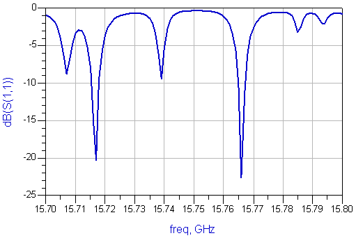 Figure 11: Reflection parameter S11 of array antennas
The radiation pattern of this array of antennas is shown in figure 12. It is gathered in the main four lobes. The gain at the resonance frequency of 15.77GHz is 9.76 dB and the directivity is 11.24 dB.
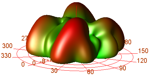 Figure 12: Radiation pattern of array antennas
The designed array antennas are showing excellent gain and directivity at the resonating frequencies with high radiation efficiency.
3.4. Equivalent circuit of solar cell antenna
Solar cell equivalent circuit is specially simulated in Advanced Design System for measuring power (P), current (I) and voltage (V). Microstrip antenna equivalent circuit is separately simulated and the same output is measured. Finally both microstrip and solar cell circuits are combined and output is measured. While comparing both outputs, combination of microstrip and solar cell equivalent circuit produces high voltage (V), current (I) and power (P). The simulation of SOLAN in ADS provides the following values of current (I) =872.8mA Voltage (V) =8.728mV and Power (P) =7.6177984mW were measured as shown in Figure 13.
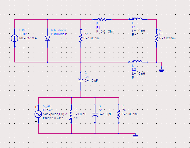 Figure 13: Equivalent circuit of solar cell antenna
3.5. Decoupling RF/DC in solar cell antenna proposed
Since the solar cell has a DC circuit, the direct current path must be decoupled from the RF signal path in such a way that the DC load has no influence on the RF properties of the antenna. The decoupling can be realized by means of concentrated reactive elements and distributed elements, respectively. In this case, we propose an inductive and capacitive RF/DC decoupling circuit shown in Figure 14.
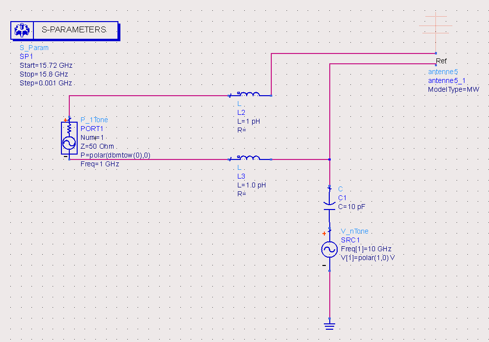 Figure 14: RF/DC decoupling circuit
The decoupling circuit was simulated (see Figure 15) and values are compared to the S11 parameter shown in Figure 8. The simulation of the reflection parameter S11 of decoupling circuit provides the same result of resonant frequency of the proposed solar cell antenna in Layout with a slight increase of return loss.
After RF/DC decoupling, this solar cell antenna can meet the purpose for which it is being studied energy harvesting for the relevant telecommunication system power supply and RF transmission. Based on the simulations results obtained, the solar cell antenna proposed here can be used for ku band satellite communication. Figure 16 explains well the operation of this solar cell antenna.
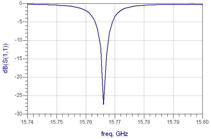 Figure 15: Simulation of RF/DC decoupling circuit
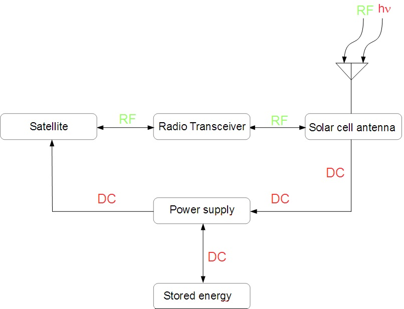 Figure 16: Self-contained wireless system with solar cell antenna
4. Conclusion
In this paper, we presented a solar cell antenna with leaf-shaped patch. This optically transparent antenna is particularly well adapted for energy harvesting and for the RF transmission in Ku band with a large gain. Good performances are obtained for this solar cell antenna, as a PV cell with its collected electrical power and as an antenna with its gain 5.77dBi and 9.76 dBi of array of antennas, directivity and efficiency. We conclude that the hybridized method where the patch element of a patch antenna has been replaced by a solar cell is more efficient than a simple integration where the patch antenna was placed directly on the solar cell is what which limited the available area of the cell and consequently a loss of electrical energy collected.
- Maharaja M., Kalaiselvan C, “Integration of Antenna and Solar Cell for Satellite and Terrestrial Communication”. International Journal of Scientific and Research Publications, 3(5), 2013.
- Danesh, M. and J. R. Long, “An autonomous wireless sensor node incorporating a solar cell antenna for energy harvesting”, IEEE Trans. Microw. Theory Tech, 59 (12), 3546–3555, 2011. DOI: https://10.1109/TMTT.2011.2171043.
- Shynu, S. V., M. J. R. Ons,P. McEvoy,M. J. Ammann,S. J. McCormack, B. Norton, “Integration of microstrip patch antenna with polycrystalline silicon solar cell”. IEEE Trans. Antennas Propag, 57 (12), 3969–3972, 2009. DOI: https://10.1109/TAP.2009.2026438.
- Suresh Kumar, S. Sundaravadivelu, “Performance analysis of solar cell antenna with hybrid mesh and aght-8 material”. Scholarly Journal of Scientific Research and Essay (SJSRE), 3(4), 51-55, 2014. DOI: http://dx.doi.org/10.1109/ghtc.2011.14.
- Yurduseven, O., Smith, D., Pearsall, N., Forbes, I, “A solar cell stacked slot-loases suspended microstrip patch antenna with multiband resonance characteristics for WLAN and WIMAX SYSTEMS”, Progress In Electromagnetics Research, 2013, 142, 321–332. DOI: http://dx.doi.org/10.2528/pier13081502.
- Ons, M.J.R., Shynu, S.V., Ammann, M.J., McCormack, S., Norton, B, “Investigation on Proximity-Coupled Microstrip Integrated PV Antenna”, IEEE Antennas and Propagation,EuCAP 2007, 3, 1–3. DOI: http://dx.doi.org/10.1049/ic.2007.1374.
- Clasen and R. Langley, “Meshed patch antennas,” IEEE Transactions on Antennas and Propagation, vol. 52, pp. 1412-1416, 2004.
- Baccouch, D. Bouchouicha, H. Sakli, T. Aguili, “Patch Antenna on a Solar Cell for Satellite Communications”. International Journal on Communications Antenna and Propagation, 6(6), December 2016. DOI: https://doi.org/10.15866/irecap.v6i6.9807.
- Baccouch, H. Sakli, D. Bouchouicha, T. Aguili, “Patch antenna based on a photovoltaic solar cell grid collection”. 2016 Progress in Electromagnetic Research Symposium (PIERS). DOI: https:// 10.1109/PIERS.2016.7734278.
- Baccouch, H. Sakli, D. Bouchouicha, T. Aguili, “Patch Antenna based on a Photovoltaic Cell with a Dual resonance Frequency”. ADVANCED ELECTROMAGNETICS, VOL. 5, NO. 3, November 2016. DOI: https://10.7716/aem.v5i3.425.
- Turpin, T. W. and R. Baktur, “Meshed patch antennas integrated on solar cells. IEEE Antennas Wireless Propag. Lett, 2009, Vol. 8, 693– 696. DOI: https://10.1109/LAWP.2009.2025522.
- A. Balanis, Antenna Theory Analysis and Design. Hoboken, NJ: John Wiley and Sons, 2005.
- Baccouch, D. Bouchouicha, H. Sakli and T. Aguili, “Optimization of the Collecting Grid Front Side of a Photovoltaic Cell Dedicated to the RF Transmission”, 2nd International Conference on Automation, Control, Engineering and Computer Science ACECS, 22- 24 March 2015 – Sousse, Tunisia.
- Baccouch, D. Bouchouicha, H. Sakli, T. Aguili, “Patch Antenna on a Solar Cell for Satellite Communications”. International Journal on Communications Antenna and Propagation, 6(6), December 2016. DOI: https://10.15866/irecap.v6i6.9807.
- Titaouine, “Analysis of Antennas Micro ruban by the model of the cavity, the model of the transmission line and the method of moments”, Magister thesis University Ferhat Abbas, Sétif, 1998.