
Development and Usability Evaluation of Mobile Augmented Reality Contents for Railway Vehicle Maintenance Training: Air Compressor Case
Volume 9, Issue 1, Page No 91-103, 2024
Author’s Name: Gil Hyun Kang1, Hwi Jin Kwon2, In Soo Chung1, Chul Su Kim1,a)
View Affiliations
1Industry-Academic Cooperation Foundation, Korea National University of Transportation Uiwang, 16101, Korea
2Department of Railroad Convergence System Engineering, Korea National University of Transportation, Uiwang,16101, Korea
a)whom correspondence should be addressed. E-mail: chalskim@ut.ac.kr
Adv. Sci. Technol. Eng. Syst. J. 9(1), 91-103 (2024); ![]() DOI: 10.25046/aj090109
DOI: 10.25046/aj090109
Keywords: Augmented reality, Railway vehicle maintenance, Air compressors, Usability evaluation, Mobile devices

Export Citations
The air compressor of a railroad vehicle is an important equipment that produces compressed air used in braking systems. New visual interaction techniques were proposed and evaluated to develop effective augmented reality content for maintenance support and training of this device. To this end, modeling techniques capable of fast animation, storyboard production to support light maintenance, and visualization algorithms that implement fluid flow have been developed. In the case of air compressors using compressed air, 2D-3D line matching distance calculation algorithm and modified flow generation algorithm were proposed to implement fluid flow for visualization. If two algorithms are used at the same time, the educational effect can be enhanced by visualizing the air flow in the 3D object simultaneously on a 2D air pipe diagram. In addition, the use of flow generation algorithm alone can visualize fluid flow or quantity control, such as air discharge or lubricant supplementation. As a result of usability evaluation of 100 users of the developed air compressor augmented reality content, the system usability scale score was 76.65, which was good. Similarly, the user experience score using six questionnaires was very good with an average of 4.12. Therefore, it was found that this training content could be used very effectively for air compressor maintenance support and training at the site.
Received: 06 December 2023, Revised: 11 January 2024, Accepted: 11 January 2024, Published Online: 20 January 2024
1. Introduction
Since railway vehicles are a means of mass transportation, it is important to perform reliable maintenance to avoid causing traffic congestion to many passengers if a failure occurs during train operation. Therefore, vehicle failures have been prevented through periodic preventive maintenance, and the lifespan of important parts has been managed and maintenance cycles have been extended through Reliability-Centered Maintenance (RCM) based on failure statistics analysis [1]. Modern railway vehicles have developed into a complex system in which various technologies are fused with the development of electronic and control technologies. In order to fully carry out the maintenance of railway vehicles with such modern advanced technology, not only the improvement of maintenance technology but also the educational techniques of maintenance personnel need to be innovated. Recently, with the development of sensor technology and communication technology and Artificial Intelligence (AI) technology, the maintenance of railway vehicles has rapidly developed into predictive maintenance by Condition-Based Maintenance (CBM) and smart maintenance [2]-[4].
Most railway vehicles remained at the level where vehicle computers installed in intermediate vehicles and driver cabins, but event recording and information on major devices during train operation were displayed with driver front monitors and vehicle computers. Recently, however, more than 2,000 sensors have been installed and monitored to switch to a level that utilizes condition monitoring and AI technology during train operation to perform failure diagnosis as well as failure prediction and residual life prediction [5,6]. The core of this change is data-based analysis technology according to the development of computer and communication technology. Since these technologies essentially utilize AI and Internet of Things (IoT) technology using ground and onboard servers, it is expected that there will be a major change in the maintenance of the conventional human-dependent experience base. The Korean railway industry is also conducting a research project for smart maintenance of railway vehicles to overcome these technological changes as follows: (1) Predictive maintenance based on CBM by increasing the capacity of new sensors and data communication, (2) Automation of the acquisition of railway vehicle light maintenance data when a vehicle in operation through a large scale vehicle scanner installed on the ground passes through a specific point such as a deposit entrance or terminal station, (3) Digitization and automation of inspection and repair records for digitization of maintenance data and connection with mobile devices, and (4) Augmented Reality(AR)-based maintenance training to replace existing computer-aided electronic manuals and mobile device-linked maintenance education contents. Research to apply AR techniques in the industry was initially a study related to the development and production of automobiles and aircraft, which was intended to be used for crash analysis, assembly optimization of batch products, and assembly production technology of complex systems [7,8]. In the automobile industry, driving support using head-up displays, assembly, design, assembly, maintenance, and manufacturing were reported as examples in the fields of in-car systems, design, maintenance, and manufacturing, such as marker-based or markerless graphic modeling using head mounted displays and AR glasses [9]-[12].
Research which applies AR technology to maintenance is also gradually expanding in the field of automobiles, starting with the maintenance of specific devices of aircraft and ships with high operational safety priorities, and railway vehicles [13]-[15]. These technological advances can be confirmed through various research survey papers [16,17].
For more than a decade, the railway sector has tried to apply AR technology to the maintenance and repair of railway vehicles using mobile devices, but it has remained at a very slow development due to the complexity of railway vehicles and limitations of IT technology [18]. The main reason for this was that the method of training many people at the same time in theoretical education and vehicles without a special education system was simple and the cost of education was low. However, this field practice is suitable for disassembling and assembling at the level of looking at and explaining the physical appearance, but there was a clear limit to education to understand the specific operating principles of complex equipment consisting of many wiring pipe checkpoints and to train complete maintenance. In addition, there is a problem that on-site classes have a high risk of safety-related accidents. Therefore, research on alternative education using video or virtual reality has been continuously conducted because the actual effect of education and training cannot be high except for education and training performed with expensive practical equipment. Recently, AR technology has also developed rapidly, such as virtual simulation of automobiles, visual design, virtual protection, and AR self-serving to reduce development costs, with the development of high-performance CPUs and graphic cards, 3D scanners, and the development of the game industry where animation technology is important [19,20]. In addition, active research is being conducted by expanding not only building infrastructure but also various manufacturing industries [21,22]. Nevertheless, the development of AR technology in the maintenance field of railway vehicles led by railway operators was very limited.
Recently, most of the AR application cases for maintenance in the railway vehicle sector have been developed mainly on main mechanical equipment such as boogie and braking devices conducted by the research group of the National University of Transportation in Korea [23,24]. In the case of the air compressor conducted in this study, only some applications have been reported to manufacture industrial screw-type air compressors [25]. Therefore, this study aims to make it easy to use for train fleet maintenance by gradually converting important railway vehicle equipment, a collection of complex technologies such as mechanical engineering, electrical, communication, and electronic engineering, over several years to innovate existing manual-based maintenance methods in the railway industry.
Unlike previous studies such as object search and maintenance point search using head-ware devices and cameras, which are many AR research fields, this study aims to create a 3D AR model and connect this model with a database related to maintenance and a storyboard to enable reliable maintenance support and to effectively perform maintenance training with realistic content in 3D space with touch function on mobile devices [26]-[28]. This study aims to achieve the research objectives for supporting on-site maintenance of major railway vehicle equipment and effective education and training at low cost as follows: (1) Development of mobile-based maintenance support and educational training contents using AR technology, replacing the existing training methods of limited and inefficient document-based theory education and field practice, virtual reality video or Internet-based e-learning, (2) The development of contents that increase work efficiency by raising detailed information of major equipment and sub-components to the same level as actual field work. Therefore, the sub-component system is based on the part procurement BOM of the operator. Development of contents connected to tools for disassembly and assembly of parts, measuring devices or instruments for inspection, special equipment, and work procedures based on the maintenance manual,
(3) Development of algorithms that enhance learning effect by implementing fluid or electric flow simultaneously with 3D AR models for operating principles and functions of equipment learned in 2D space from piping, wiring, and circuit diagrams to enhance maintenance support and education and training effect,
(4) Analyze maintenance tasks to extend the user interface to inspect, measure, repair, and, Expanding practical education and training areas to provide a sense of immersion through physical equipment and interfaces, such as similar tools, etc., and
(5) It increases the effectiveness of safety work through warnings related to safety work based on the operator’s disaster database, such as serious injuries or deaths that may occur at the maintenance site.
The usability of AR contents developed for railway vehicle air compressor maintenance training was evaluated in two ways. The results of the System Usability Scale (SUS) survey and the User Experience (UX) experiment of 100 college students who are beginners in railway vehicle maintenance were as follows. The average SUS score of AR contents was 76.65, which was “Good.” In addition, the results of the UX survey shows that the average usability score for six questionnaires was excellent at 4.12 out of 5. Therefore, AR content developed for Android-based mobile devices is expected to be conveniently used for maintenance training on a platform for maintenance efficiency for beginners in railway vehicle maintenance.
2. AR Contents and Developed Algorithm
2.1. Smart Maintenance Platform for Railway Vehicle
The Smart Maintenance Research Consortium Group, which includes the Korea Railroad Corporation, the Korea National University of Transportation, Hyundai Rotem, a railroad vehicle manufacturer, Seoul Metro, and AI software development companies, has been carrying out the railway vehicle smart maintenance research project with the support of the Korean government since 2019. Figure 1 shows the architecture of the final stage, the smart maintenance platform. The basic strategy is to install sensors on the main components of Electric Multiple Unit (EMU) and implement CBM and data analysis-based predictive maintenance in combination with AI. In addition, to improve maintenance efficiency, a maintenance decision-making system is established to support maintenance decisions in conjunction with CBM data by automating inspection and measurement and digitizing data. Finally, it is to establish a Mobile Maintenance Efficiency System (MMES) that promotes new innovation in automating maintenance records to support the implementation of new maintenance strategies and training employees using AR in mobile systems. This study introduces the development of AR contents that replace or support existing field training along with this MMES AR manual, and specifically relates to the process of developing AR contents for air compressors and the result of the user evaluation.
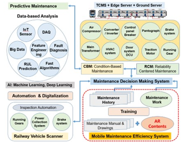
Figure 1: Architecture of Smart-maintenance platform for Railway vehicle
Train configurations vary from country to country due to population density, urban traffic characteristics, and traffic congestion. In the case of urban railroads in Seoul, a metropolitan city, 3 to 4 cars are built into one unit, and two units of 6 cars and 3 units of 10 car trainset is generally operated. Most of the major trunk lines are mass commuter transported by EMUs composed of 10 car trainset. The type of vehicle is also divided into a motor car with a propulsion device, a trailer car without power, a trailer car with cabin, and a motor car with cabin if there is a driver’s room. However, most of the main equipment is installed in one unit, and when the number of unit increases, the device overlaps, but since it is the same equipment, AR contents can be manufactured for each major equipment. Most urban rail vehicles are direct current EMUs using DC 1500V, while long-distance trains operated to the suburban lines are AC EMUs using 25kV AC [29,30]. In addition, in the case of AC-DC multiple EMU, a converter is added to the propulsion system, including the main transformer, making the vehicle complicated by installing ultra-high voltage power devices and switches. Table 1 shows the AR manuals and contents of major equipment for EMU developed as a Korean government-funded research project until recently.
Table 1: Developed AR manual and contents
| Equipment | EMU | AR manual | AR training |
| Pantograph | AC/DC | ○ | ○ |
| Main transformer | AC | ○ | |
| Air compressor | common | ○ | ○ |
| Propulsion system | AC/DC | ○ | |
| Traction motor | common | ○ | |
| Auxiliary power | common | ○ | |
| Battery box | common | ○ | |
| Bogie | common | ○ | |
| Wheelset | common | ○ | |
| Axle box | common | ○ | |
| Access door | common | ○ | ○ |
| HVAC | common | ○ | |
| Brake operating unit | common | ○ | ○ |
| Wheel brake system | common | ○ | |
| Disk brake system | common | ○ | |
| Air spring | common | ○ | |
| Front connector | common | ○ | |
| Inter connector | common | ○ |
The reason why AR manual and AR contents differ on the MMES platform is that different small groups have different development objectives and different intellectual property owners. Therefore, some equipment is developed and compared with each other, and some equipment has been developed independently, but plans to optimize in the future through upgrades.
2.2. AR contents for Mobile Maintenance Efficiency System
Figure 2 shows the MMES installed on the mobile phone and the drive screen. The left side shows the app screen installed on the mobile phone and the screen consisting of maintenance work, maintenance manual, maintenance record, and AR content in the center. The picture on the right shows the developed AR manual screen by pushing the menu. The MMES platform was developed for the main purpose of digitizing maintenance records for smart maintenance, and when users perform maintenance and move to designated routes, and store maintenance history on digital workbooks according to maintenance guidelines, data is transmitted to ground servers, and AR manuals were produced to support maintenance in this process.
Figure 3 shows the screen of AR contents developed by the KNUT research team for educational and training purposes. It can be used by using a separate AR contents app on the upper left side of the left screen of Figure 2.
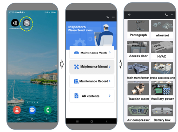
Figure 2: The AR manual screen for MMES
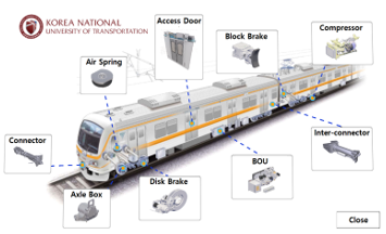
Figure 3: The AR training APP screen for MMES
3. Development of AR contents for Air Compressor
The air compressor of a railway vehicle is one of the essential equipment for starting, operating, and stopping trains. When starting an electric railway vehicle, compressed air is used to raise the current collecting pantograph to supply high-voltage electricity by contacting the power wire. During train operation, air is supplied to the braking device to stop the train at the station, and compressed air is supplied to the door system to enable passengers to get on and off the train. In the case of the 10-car electric vehicle of the Korea Urban Railroad, three sets are installed on the lower floor of the body, as shown in Figure 4. At least one air compressor is required for each train configuration unit. Modern air compressors are mainly reciprocated or screw types. In the operation, the motor is rotated to compress atmospheric pressure air to high pressure, store compressed air in the main air reservoir, and use compressed air to automate the brake system and opening and closing doors of the train. In the case of long-distance passenger trains, it is also used to supply water to the toilet or to provide water for handwashing. Thus, as with braking systems, air compressor maintenance training is important.
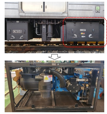
Figure 4: Air compressor of the Electric multiple unit
3.1. AR Contents Development Process
To produce AR content for maintenance, it is necessary to select and model equipment for content and organize and design content. Figure 5 shows the planning and design procedure of AR content.
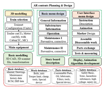
Figure 5: Procedures of AR contents planning and design
Modeling of an equipment assembly of a railway vehicle takes time and cost to model because the assembly is relatively large size and the number of parts is large, and there are typical methods as follows. (1) Using the parts manufacturer’s 3D drawings to convert to a format for an AR production program: It uses 3D CAD files, which is the most convenient method. (2) 3D scanning and measurement methods: 3D scanning parts are modeled by using scanners, and the rest are modeled by making cad drawings. (3) Model with similar dimensions: less precision, but with reference to drawings and real objects modeled with similar dimensions.
Figure 6 shows a 3D modeling technique that uses the Geometric Design X and Unity program to convert air compressor large CAD raw files into FBX to read reduced capacity files and convert them into APK format models, small files that run fast on mobile devices [31]. Depending on the type of equipment, 3D CAD format file formats are mostly large in capacity and cannot be used directly on mobile devices. It is also important to use a 3D scanner to create an initial device model file, since 3D CAD files are the most accurate models.
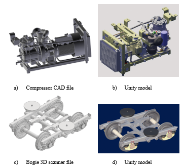
Figure 6: 3D modelling for AR contents
Figure 7 shows an example of modeling an air compressor by acquiring external coordinate data using a 3D scanner. It is essential to read and check it in the CAD program, then convert it to FBX format so that Unity programs can import and work on AR content.
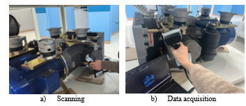
Figure 7: Process of using a 3D scanner
Table 2 shows a comparison of file size of among the air compressor, a railway vehicle bogie and brake operation unit. The bogie case is a small capacity CAD-compatible file STP format using a 3D scanner, despite being a large structure. As shown in Table 2, 3D scanner files are only 6.8 M, which is advantageous for fast animation. Of course, the CAD program SolidWorks drawing file increases the file size to about 168MB only for the bogie frame.
Table 2: 3D modelling and file size
| Equipment | cad file/3D scanner file size | Unity import file size (fbx) |
| Compressor | 288MB(3D cad file) |
68MB (77% reduced) |
| Bogie |
168BM sdlprt file (frame only) 6,497KB stp file/3D scanner |
9,427KB |
| BOU | 115MB(3D cad file) |
22MB (81% reduced) |
Therefore, for single structures that do not require disassemble, the dimensional information file of the 3D scanner is very efficient in creating AR models. This seems to be due to the fact that the welding structure of the truck frame is perceived as a part on the scanner, unlike the 3D CAD file, whereas the air compressor 3D CAD file consists of many subsystems, and the complexity of the structure increases the size of the CAD file.
3.2. Creating Storyboard for Maintenance
Storyboards are an important process of determining the overall structure of content and determining the hierarchy of objects to be implemented as unity, and determining the validity of training to determine information to be delivered to users. (1) Basic menus such as device general information, level determination of sub-components of the device, and maintenance classification are defined through the content major classification of the selected equipment assembly. (2) In order to avoid unity hierarchy complexity in content production, sub-menus are defined by integrating the middle and sub-classification levels. Design various levels of administration that describe objects and other functions in drawings of device sub-parts at the level required by the manual or implement the operation. At this stage, various scripts are prepared in conjunction with databases related to parts and sub-parts. (3) Maintenance defines the scope of development of the AR manual implemented by the operating company and MMES, and various scenarios such as assembly/disassembly, measurement and inspection taking into account other tools, equipment, and special instruments in the degree of exchange repair, and the contents related to training, maintenance support, and safety work.
In this way, storyboard creation determines the quality and system efficiency of the entire content, so it should be written in collaboration with maintenance experts to understand the level that can be implemented with development programs or algorithms in a systematic approach and implementation virtual space, and to have a high training effect. Figure 8 shows basic architecture of storyboard of air compressor.
Table 3 shows that classifies detailed tasks that are frequently repeated in railway vehicle maintenance work by category, and classifies training purposes by type and methods implemented as AR contents. A storyboard should be created by focusing on such work content and reviewing the maintenance manual database and maintenance regulations.
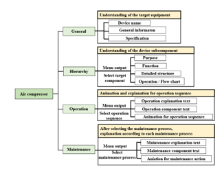
Figure 8: Storyboard creating for AR contents
Figure 9 is an example of a storyboard created during the development process. The left part of Figure 9(a) shows the screen configuration interface and text, sand the right part shows the content scenario that the user needs to learn. Figure 9(b) is an example of a visualized storyboard, and the progress of the animation, the setting by time, and the additional functions that appear on the screen are written in detail. The detailed storyboard is continuously updated and managed if a change is needed.
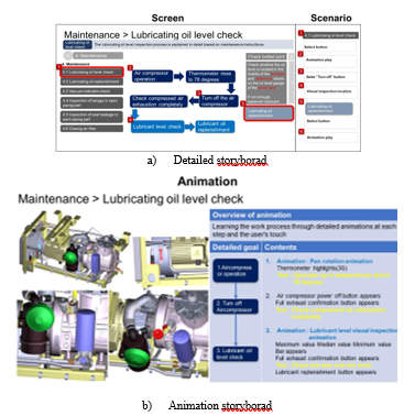
Figure 9: Example of storyboard
3.3. Algorithm Development for Flow Expression
The main algorithm used in the air compressor training content is as follows. Algorithm 1 is the 2D-3D Line Matching Distance Calculation (2D-3D LMDC) algorithm that calculates basic coordinates and travel distances to implement electricity or fluid flow at the same time. The original purpose of this algorithm was developed as a streamline matching variable calibration algorithm to make it easy to understand education and training of complex devices including circuit diagrams or pipes by displaying many 2D drawings widely used in railway vehicles in 3D space from real devices.
Table 3: Maintenance work definition for AR contents
When used with Algorithm 2, Flow Generation (FG) algorithm, this algorithm can simultaneously display the electrical wiring diagram of the control circuit and the display of electrical flow from the actual wire, or the 2D air flow diagram of the brake system and the flow of compressed air or control air from the actual 3D pipe. An animation duration is obtained by calculating the distance from spatial coordinates with different dimensions and calculating the position that can display the same flow in space at the same time. Figure 10 shows the same flow matched to each other in the 2D drawing and 3D model. Because it passes through the same location value, it is easy for users to learn by comparing each other.
| Algorithm 1: Code of the 2D-3D Line Matching Distance Calculation algorithm | ||||
| Result: = Animation Duration · } | ||||
|
Animation Duration AD; Vector3 Position List P[P1(x,y,z),P2…Px]; Produce List of Distance D; |
||||
| for (i = 0, , i++) | ||||
| //Calculate Distance and D1(Pi – Pi+1) …Di =Distance( , ))= = AD · |
||||
| end | ||||
| Algorithm 2: Code of the Flow Generation algorithm | ||||
| Result: Particle System Quantity-Control | ||||
|
Object Prefab; float Qcontrol; // Quantity-Control |
||||
| for (i = 0, , i++) | ||||
|
Instantiate Object Prefab As a on Pi Rotate a to look Pi+1 Set a.Particle System. Lifetime, Speed, Qcontrol, Emission.rate Over Time Lifetime = Speed = Emission Rate over Time = Start Speed Qcontrol += Qcontrol |
||||
| end | ||||
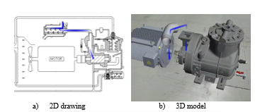
Figure 10: Flow displayed in 2D drawings and 3D models
The FG algorithm is an algorithm that makes it easy to express the flow of fluid in AR. This algorithm was originally developed to support the LMDC algorithm, allowing electricity or fluid to display the flow on the drawing by continuously flowing objects represented by dots. Since then, in the development of air compressor AR content, it has been expanded to display oil or air exhaust at the valve outlet. This called Prefab of Unity to enable the repetitive use of objects with specific attributes [32]. In order to express the pneumatic flow in 3D at the time of need, it is a method of instantiating the particle prefab with the properties of the particle system input. The module of the particle system was automatically modified once each attribute was entered to avoid the complexity of using a variable containing 24 properties that affect the entire system. When entered into the modified particle prefab, the prefab is instantiated, releasing the particles continuously, which has the effect of displaying the flow. It can also show arbitrary discharged airflow using random numbers and particles emitted by property changes. Figure 11 shows the detail process of the FG algorithm. It is released by each phase that increases the particles, giving a visual effect of creating a moving flow of electricity or compressed air.
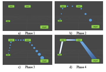
Figure 11: The process of generating a flow as particles increase using the FG algorithm
Figure 12 shows a flow chart of the algorithms that combine two developed algorithms to display electricity or fluid flows simultaneously in a 2D drawing and a real 3D object on one screen, or to control the flow of fluid using a single fluid flow generation algorithm to generate a screen such as air discharge.
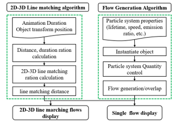
Figure 12: Flow chart of the algorithms for AR contents
Figure 13 shows the exhaust air at the outlet of the air compressor in a three-dimensional space using the FG algorithm alone. In this way, by showing the flow of fluid in various ways through Q-control, various functions of maintenance such as pressure control and exhaust air control can be actively shown to the trainee, thereby enhancing the training effect.
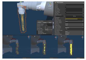
Figure 13: Fluid flow expression with quantity control for AR contents
3.4. Development of Menus for User Interaction
When the storyboard is completed, it is necessary to develop user menus to implement AR content on mobile device screens. In particular, menu arrangements that require using a limited narrow space were allocated in consideration of space use so that other menus were not pushed.
Figure 14 shows an example of menu configuration in a User Interface (UI) of air compressor AR content. The menu used for the content is located on the left and right sides of the screen so that the device is displayed in the center. The menu consists of three types.
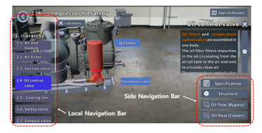
Figure 14: Menu design for sub-parts of air compressor
Figure 15 shows a detailed example of the three types of menus. The Global Navigation Bar (GNB) on the left, as shown in (a), is the main menu. This is a large category menu in GNB format, consisting of General, Hierarchy, Operation, and Maintenance, which are the highest levels of keywords for the maintenance process. When one of the GNB menus is touched, the Local Navigation Bar (LNB), a sub-menu of the GNB, appears, as shown in (b). Each LNB menu consists of maintenance process and necessary related information. The LNB is placed on the left side of the screen, and at the same time, a Side Navigation Bar (SNB) as shown in (c) is displayed on the right side. SNB is displayed with detailed information such as text and photos in a separate pop-up window [33]. In addition to this, there is “Hide menu” and “Open Scheme”.
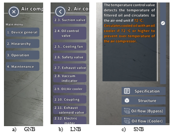
Figure 15: Detailed examples of menu types
In the early development version, GNB and LNB were placed on the left and right sides, but in the upgraded version, when the GNB is touched, the GNB menu disappears and the screen space can be used widely with a screen configuration replaced by LNB.
Figure 16 shows the enlarged screen space by moving the original right LNB to the left. Therefore, even a mobile phone with a small screen can use the screen widely for device screen.
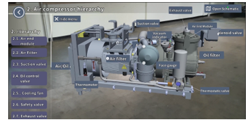
Figure 16: Enlarged screen space by moving the original right LNB to the left
3.5. Subcomponent Display Techniques
The developed model is assembled into sub-components, which are based on the maintenance manual and the replacement part procurement system using hierarchy and can identify individual parts from the assembly. It allows for a perceptive effect, and when a particular part is selected in the assembly, the assembly status can be easily identified by using a different color or by inserting an outline at the boundary between the equipment and sub-components. When the structure menu of SNB is touched at the component level, the sub-part is unfolded, and the name of the component is displayed with animation and buttons to make it easier for the user to understand the complex component, and if necessary, a separate SNB can be used to show the procurement product number of the component. This process is already detailed in the hierarchical design stage, but missing and insufficient functions or animations can be inserted additionally during use through content editing to increase completion. Therefore, through this content design, users can check the connection of device components and open the detailed structure between components in the center of the screen in detail, making it convenient to understand the entire device without disassembling the actual components one by one as shown in Figure 17.
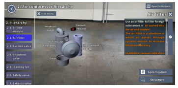
Figure 17: Subcomponent display screen of air filter assembly
The SNB-type menu on the right side of the window is mainly installed at the bottom of the movable window that can display detailed descriptions and other information about components. The SNB menu is used to show sub-parts in a disassembled structure, deliver operational information related to sub-parts, or animate compressed air, electricity, oil flow, etc. to help trainers understand and improve the convenience of maintenance training.
3.6. Maintenance Instruction Implementation for User Training
In the GNB menu, the maintenance menu mainly implements the maintenance items, contents, duration, procedures, inspection, repair and replacement methods of equipment by maintenance level required by the manufacturer in the manual approved by the vehicle operator, and the pre-learning support function for the replacement of spare parts and consumable parts. Sub-component contents such as oil amount, supplemental level, and exchange cycle related to the oil filter may be implemented as text in a pop-up window. In this way, the important information of the component is displayed visually to the user.
Figure 18 is a case screen showing lubricating oil filters and lubricating oil replenishment work among maintenance items. There is a maintenance support window built with a movable window that shows the process of replacing the lubricant filter. This content can train users by clearly presenting replacement of consumables, replacement of lubricating oil, supplementation procedures or criteria.
Maintenance AR content includes the ability to effectively pre-learn the replacement process of parts that have reached the replacement cycle. In the figure, the scene where the valve is opened and the lubricant is replenished from the lubricant plastic container to the refueling hole is realized as if it were real by algorithms that show fluid flow. The animation is also implemented with detailed procedures in the pop-up window, allowing users to effectively understand lubricating oil replenishment and learn how to do it.
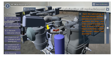
Figure 18: Maintenance instruction for lubricating oil replenishment
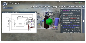
Figure 19: Implement fluid flow simultaneously in 2D pipe drawings and 3D model.
Figure 19 shows the function of implementing fluid flow simultaneously in a 2D pipe drawing and a 3D model. The algorithms described in the previous section are used to provide effective theory education as well as to allow users to easily understand the operating principles of complex devices.
3.7. Safety Warning Function for Hazardous Maintenance Work
The maintenance work of railway vehicles includes various danger and hazard factors, which can lead to serious injury or even death of workers. Therefore, AR content needs to include the ability to proactively train these risks.
Figure 20 shows examples of safety warnings displayed in this content. (a) is a warning message to avoid burn hazard caused by touching hot areas during air compressor maintenance. (b) indicates a warning against body or other contact with cooling fans, coupling rotating parts, etc. (c) shows a safety warning to ensure that the air is exhausted in the pipe before starting work and to prepare for an unexpected situation where compressed air is ejected from the valve. This content reminds workers of things to pay attention to before and after starting work, and also makes workers aware of unexpected situations that may occur.
In addition, various risk factors such as electric shock caused by high-voltage electricity or serious injury caused by vehicle rolling are warned using appropriate warning text and sound effects. In particular, you can use red or yellow visually to highlight the hazard with highlights. Additionally, various pop-up windows can provide detailed explanations of maintenance hazards, such as handling toxic substances and pollutants.
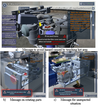
Figure 20: Caution and warning messages for safety
3.8. Finger Gestures on Mobile Device Touchscreen
This content can use a manipulation gesture that can control the location, size, and rotation of the 3D model using the mobile device’s touch screen method. Table 4 shows the detailed functions of the 3D model manipulation interaction as an example [34]. Maintenance content users can open the app on the mobile device screen, use the menu to load content on the screen, and use touch-type manipulation technology to perform training and maintenance work [35].
Table 4: Touch gesture for touchscreen manipulation
| Value to change | Corresponding | Touch gesture |
| Position | swipe | |
| Scale | pinch/spread | |
| Rotation | twist |
Figure 21 is a photograph showing the inspection and work in front of the air compressor of a railway vehicle using the AR air compressor content of a mobile phone. The produced content is compatible with various screen sizes based on Android first. Using AR content, it overcomes the shortcomings of time, space, and manpower management, which are obstacles to existing document-based manual education, receives database information of a separately developed maintenance server, and is effectively digitized in conjunction with actual digital maintenance work records.
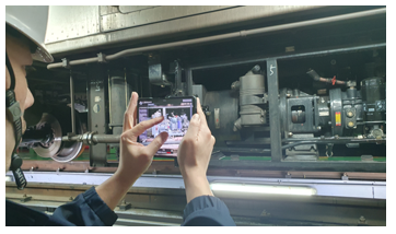
Figure 21: A photo of using mobile phone apps on the side of the vehicle at depot
4. Usability Evaluation
The usability of the developed AR content can be performed using various methods. A commonly used technique is to use the content developed by the user group, then conduct a survey and analyze the results. These techniques include the SUS, the Computer System Usability Survey (CSUQ), and the Usability Indicator for User Experience (UMUX) [36]-[38].
In order to evaluate the usability of the developed AR content, a SUS survey and a survey on UX techniques were conducted on 100 college students who majored in railway vehicle systems, respectively. Table 5 show the participants of the usability evaluation experiments [39].
Table 5: The participants of the experiments
| Experiment participants | 100 students |
| Average age | 23.8 years |
| Male | 73 |
| Female | 27 |
4.1. SUS
The SUS, as a quick and dirty usability scale is reliable tool for measuring the usability, originally created by John Brook in 1996 [40]. SUS survey consists of a 10 item questionnaire with 5 response options for participants of a scale of 1 to 5. Scale score 1 means strongly disagree and scale score 5 means strongly agree. Table 6 shows the modified SUS survey questions in this study [41]. The survey was carried out after using the AR contents.
Table 6: The modified SUS statements used in this study
| No. | Questions |
| Q1 | I think that I would like to use this AR content product frequently |
| Q2 | I found the AR content unnecessarily complex |
| Q3 | I thought the AR content was easy to use |
| Q4 | I think that I would need the support of a technical person to be able to use this AR content |
| Q5 | I found that the various functions in This AR content were well integrated |
| Q6 | I thought that there was too much inconsistency in this AR content |
| Q7 | I would imagine that most people would learn to use this AR content very quickly |
| Q8 | I found the AR content very awkward to use |
| Q9 | I felt very confident using the AR content. |
| Q10 | I needed to learn a lot of things before I could get going with this AR content |
The SUS score can be calculated using the following 3 equations [42].
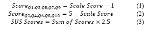
Equation (1) is used to get the odd number question scores. The even number question scores are calculated by (2). Equation (3) is used to obtain the final value of the SUS survey. The scores have a range is from 0 to 100. It can also be mapped to the following adjective ratings. Figure 22 shows a comparison of mean SUS scores by quartile, adjective ratings and the acceptability of the overall SUS score [43].
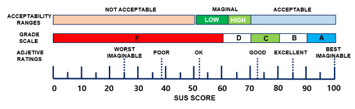
Figure 22: A comparison of mean SUS scores by quartile, adjective ratings, and the acceptability of the overall SUS score.
4.2. User Experience Experiment
Another technique, UX assessment, was conducted on AR contents. Six items related to usability were selected that were reviewed as suitable for content evaluation for maintenance of specific equipment, such as air compressors. The survey tool referred to the UX evaluation, and the detailed survey contents of the survey are shown in Table 7 [44]. An experience survey using a questionnaire tool developed after the user used AR content for air compressors was conducted and analyzed.
Table 7: Indicators of Usability assessment
| Categorized Items | Questionnaire details |
| Simplicity | Appearance of AR content, function provision method, simplicity of procedures. |
| Accessibility | User should be able to access AR content smoothly. |
| Efficiency | It should be possible to derive accurate results without unnecessary time consumption. |
| Informativeness | User should be able to obtain the necessary information through appropriate means and methods. |
| Learnability | User should be able to handle the interface of AR content proficiently |
| User Support | User should be able to respond well to problems that arise when using AR content. |
4.3. SUS Survey Results
Figure 23 is a graph showing the score for each SUS question of the AR contents of the air compressor. The threshold reference value for the usefulness of SUS is 68 points. The results of this survey are as follows. The items that were relatively better than other questions were Q3 “ease of using content” (87.2) and Q1 “intention to use content” (87). On the other hand, Q4 “needs for technical helpers” (68.3) and Q10 “needs for pre-learning” (69) questions scored relatively lower than other questions. This seems to be because survey participants are not familiar with the use of AR content in the screen touch manipulation method, as shown in Table 3. The average score of 10 SUS questions for this content was 76.65, which was higher than the overall threshold of 68 points for each question. In addition, the usefulness rating is “B(Good)”.
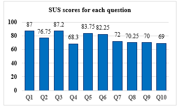
Figure 23: SUS score of the air compressor AR contents
Therefore, this content will be useful for beginners in railway vehicle maintenance. Therefore, it is considered suitable for use in the maintenance and repair training of air compressors for urban railway vehicles.
4.4. UX Survey Results
Figure 24 is a graph showing the UX evaluation results. This is the result of a survey after using AR contents developed four times. The overall average of the six questions was 4.12 points, and the score for the sense of reality item was the highest at 4.38 points. On the other hand, the score of the convenience item was 3.92, the lowest among the four items.
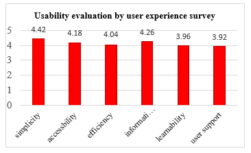
Figure 24: UX score of the air compressor AR contents
Table 8 shows the results of sub-items for each item of UX evaluation. The reason for the highest simplicity is that the maintenance procedure is simply and clearly structured to make it easier for even beginners to understand (4.58). It is presumed that various learning functions are also clearly organized based on keywords (4.41). The second highest informativeness item score is considered to be because the entire scenario of the content was systematically structured (4.38), and the text was written to make the maintenance procedure easier to understand (4.22). In comparison, the reason why the user support item is the lowest was that the description of the possible technical problems was insufficient (3.85), and the response method in case of an error was not described in detail (0.395).
Table 8: Scores of detail Questionnaire for UX
| Categorized Items | Questionnaire details | score |
| Simplicity | Smooth output of content | 4.27 |
| Simple configuration of various learning functions | 4.41 | |
| Simple and clear explanation of maintenance processes | 4.58 | |
| Accessibility | Ease of running content | 4.09 |
| Compatibility with mobile devices | 4.20 | |
| Clarity of description and usage | 4.31 | |
| Efficiency | Comparison of efficiency with existing manuals | 3.99 |
| Quickly acquire the information you want | 4.13 | |
| Increased actual work efficiency | 4 | |
| Informativeness | Provides accurate maintenance information | 4.18 |
| Understand the entire maintenance process | 4.22 | |
| Systematicity of the entire scenario | 4.38 | |
| Learnability | Seamless model touch availability | 3.96 |
| Compatibility of UI and additional buttons | 3.97 | |
| Ease of screen transition | 3.95 | |
| User Support | Description of response when error occurs | 3.95 |
| Adequacy of help and error examples | 3.96 | |
| Examples of problems that may occur | 3.85 |
4.5. Discussion
Two evaluation techniques, SUS and UX, were used to identify problems and derive improvements of developed AR content. As a result of the two experiments, a common issue is that participants have some difficulty using the content and take time to learn how to use it. They experienced some errors in the content during the experiment and expressed lack of help or countermeasures. The content was produced in consideration of the use of novice maintenance workers in the design stage, so this part was highly evaluated, but it is also considered that the use of maintenance workers who are relatively unfamiliar with digital content should be considered. In future contents, it will be necessary to produce it by receiving feedback from maintenance workers who have not been exposed to AR technology in the design stage. If additional functions such as inserting help for each function, producing tutorial version, and voice guidance are produced, high-quality content can be produced.
5. Conclusion
This study is a case of applying AR technology to the maintenance of railway vehicles and employee education and training as one of the smart maintenance research projects. AR contents that can be easily used in mobile devices for maintenance and training of air compressors for commuter electric vehicles have been developed. Two algorithms were developed and used to express fluid flows such as pressure air. In addition, in order to verify the usability of the developed content using a SUS survey and UX survey. The conclusions obtained from this study are as follows.
(1) By reducing the file size from 3D scanners or CAD original files, it is possible to implement fast animation on Android-based mobile devices. It was developed by linking training AR contents with the AR manual of the MMES, which is a high-level platform. Therefore, maintenance work and training are possible while watching actual equipment in the field depot, and maintenance support can be provided along with other equipment contents already developed or under development.
(2) The 2D-3D LMDC algorithm, which can implement flow simultaneously on a two-dimensional drawing or piping diagram and a three-dimensional equipment screen, was applied. In addition, the FG algorithm, which can control the flow rate of the fluid flow, was used to implement the movement or exhaust of compressed air, thereby enhancing the learning effect of the content.
(3) A simplified menu is placed on the left and right sides of the display screen, and the device is operated by user-friendly menu bar and touch screen operation technology on the central screen. In addition, through a systematic hierarchy structure when developing a storyboard, users can easily understand the operating principles and operations of the entire equipment, and perform reliable work by receiving detailed support for disassembly procedures and specific work methods
(4) The developed content can display components and sub-components according to the standardized BOM system of manufacturers and operators. This enables support for maintenance work using part hierarchies. In addition, through information on the replacement cycle and replacement process of spare parts based on the manufacturer’s manual, it is possible to effectively train the replacement and process of spare parts and perform necessary inspections or repairs.
(5) Due to the nature of railway vehicle parts, there is a lot of heavy equipment, and there are maintenance tasks that involve workers’ risks such as high voltage and high-pressure air. In order to eliminate safety accidents during work, safety items were visualized on a text display to generate a warning message, and a red highlight was applied to each inspection part for worker safety.
(6) The average SUS score for AR content of this air compressor content is 76.65, and the rating is “Good”. In addition, the results of the UX test showed that the average usability score for the six-item questionnaire was excellent at 4.12 out of 5 score, and this content is estimated to be quite useful for training beginners in railway vehicle maintenance.
Future research will need to expand content that has not yet been developed in the vehicle system, further develop algorithms for efficient content production, and continue to improve usability in conjunction with the AR manual of the maintenance efficiency system.
Conflict of Interest
The authors declare no conflict of interest.
Acknowledgment
This work was supported by the Korea Agency for Infrastructure Technology Advancement (KAIA) by the Ministry of Land, Infrastructure and Transport under Grant RS-2021-KA162811.
- F.A. Marten, “Reliability Centered Maintenance: A Case Study of Railway Transit Maintenance to Achieve Optimal Performance,” Mineta Transportation Institute Report, 1006, 2010.
- E. Quatrini, F. Costantino, G.D. Gravio, R. Patriarca, “Condition-Based Maintenance An Extensive Literature Review,” Machines, 8(2), 31, 2020, doi:10.3390/machines8020031.
- A.K.S. Jardine, D. Lin, D. Banjevic, “A review on machinery diagnostics and prognostics implementing condition-based maintenance,” Mechanical systems and signal processing, 20(7), 1483–1510, 2006, doi:10.1016/j.ymssp.2005.09.012.
- J. Campos, “Development in the application of ICT in condition monitoring and maintenance,” Computers in Industry, 60(1), 1–20, 2009, doi:10.1016/j.compind.2008.09.007.
- B. Zhang, Y. Sui, Q. Bu, X. He, “Remaining useful life estimation for micro switches of railway vehicles,” Control Engineering Practice, 84, 82–91,2019, doi:10.1016/j.conengprac.2018.10.010.
- C.P. Ward, P.F. Weston, E.J.C. Stewart, H. Li, R.M. Goodall, C. Roberts, T.X. Mei, G. Charles, R. Dixon, “Condition Monitoring Opportunities Using Vehicle-Based Sensors,” Proceedings of the Institution of Mechanical Engineers, Part F: Journal of Rail and Rapid Transit, 225(2), 202–218, 2011, doi:10.1177/09544097jrrt406.
- Z. Cujan, G. Fedorko, N. Mikusova, “Application of virtual and augmented reality in automotive,” Open Engineering, 10(1), 113–119, 2020, doi:10.1515/eng-2020-0022.
- T. Masood, J. Egger, “Augmented reality in support of Industry 4.0–Implementation challenges and success factors,” Robotics and Computer-Integrated Manufacturing, 58, 181–195, 2019, doi:10.1016/j.rcim.2019.02.003.
- L.F.D.S. Cardoso, F.C.M.Q. Mariano, E.R. Zorzal, “A Survey of Industrial Augmented Reality,” Computers & Industrial Engineering, 139, 106159, 2020, doi:10.1016/j.cie.2019.106159.
- R.T. Azuma, “A Survey of Augmented Reality,” PRESENCE: Virtual and Augmented Reality Issues, 6(4), 355–385, 1997, doi:10.1162/pres.1997.6.4.355.
- R. Palmarini, J.A. Erkoyuncu, R. Roy, H. Torabmostaedi, “A systematic review of augmented reality applications in maintenance,” Robotics and Computer-Integrated Manufacturing, 49, 215–228, 2018, doi:10.1016/j.rcim.2017.06.002.
- R.G. Boboc, F. Girbacia, E.V. Butila, “The Application of Augmented Reality in the Automotive Industry: A Systematic Literature Review,” Applied Sciences, 10(12), 4259, 2020, doi:10.3390/app10124259.
- H. Rios, E. Gonzalez, C. Rodriguez, H.R. Siller, M. Contero, “A Mobile Solution to Enhance Training and Execution of Troubleshooting Techniques of the Engine Air Bleed System on Boeing 737,” Procedia Computer Science, 25, 161–170, 2013, doi:10.1016/j.procs.2013.11.020.
- H. Eschen, T. Kotter, R. Rodeck, M. Harnisch, T. Schuppstuhl, “Augmented and Virtual Reality for Inspection and Maintenance Processes in the Aviation Industry,” Procedia Manufacturing, 19, 156–163, 2018, doi:10.1016/j.promfg.2018.01.022.
- M. Kans, D. Galar, A. Thaduri, “Maintenance 4.0 in railway transportation industry,” in Proceedings of the 10th world congress on engineering asset management (WCEAM 2015), 317–331, 2016, doi:10.1007/978-3-319-27064-7_30.
- A. Muller, A.C. Marquez, B. Iung, “On the concept of e-maintenance: Review and current research,” Reliability Engineering & System Safety, 93(8), 1165–1187, 2008, doi:10.1016/j.ress.2007.08.006.
- P. Cipresso, I.A.C. Giglioli, M.A. Raya, G. Riva, “The Past, Present, and Future of Virtual and Augmented Reality Research: A Network and Cluster Analysis of the Literature,” Frontiers in Psychology, 9, 2086, 2018, doi:10.3389/fpsyg.2018.02086.
- W. Zhang, B. Han, P. Hui, “On the networking challenges of mobile augmented reality,” in Proceedings of the Workshop on Virtual Reality and Augmented Reality Network, 24–29, 2017, doi:10.1145/3097895.3097900.
- J. Kiu, K. Zhang, “Design and Simulation Debugging of Automobile Connecting Rod Production Line Based on the Digital Twin,” Applied Science, 13(8), 4919, 2023, doi: 10.3390/app13084919.
- V. P. Gangwar, D, Reddy, “Hospitality Industry 5.0: Emerging Trends in Guest Perception and Experiences,” Opportunities and Challenges of Business 5.0 in Emerging Markets, 185–211, 2023, doi: 10.4018/978-1-6684-6403-8.ch010.
- E.D.N. Orihuela, O.O.V. Villegas, V.G.C. Sanchez, R.I.B. Castillo, J.G.L. Solorzano, “Mobile Augmented Reality Prototype for the Manufacturing of an All-Terrain Vehicle,” Advanced Topics on Computer Vision, Control and Robotics in Mechatronics, 49–75, 2018, doi:10.1007/978-3-319-77770-2_3.
- A. Chouchene, A.V. Carvalho, F.C. Santos, W. Barhoumi, “Augmented Reality-Based Framework Supporting Visual Inspection for Automotive Industry,” Applied System Innovation, 5(3), 48, 2022, doi:10.3390/asi5030048.
- H.J. Kwon, K.S. Kim, C.S. Kim, “Development and Evaluation of Augmented Reality Learning Content for Pneumatic Flow: Case Study on Brake Operating Unit of Railway Vehicle,” IEEE Access, 11, 46173–46184, 2023, doi:10.1109/ACCESS.2023.3273605.
- H.J. Kwon, S.I. Lee, J.H. Park, C.S. Kim, “Design of Augmented Reality Training Content for Railway Vehicle Maintenance Focusing on the Axle-Mounted Disc Brake System,” Applied Science, 11(19), 9090, 2021, doi:10.3390/app11199090.
- S. Scheffer, A. Martinetti, R. Damgrave, S. Thiede, L.V. Dongen, “How to Make Augmented Reality a Tool for Railway Maintenance Operations: Operator 4.0 Perspective” Applied Sciences, 11(6), 2656, 2021, doi:10.3390/app11062656.
- N. Hagbi, O. Bergig, J.E. Sana, M. Billibghurst, “Shape Recognition and Pose Estimation for Mobile Augmented Reality,” IEEE transactions on visualization and computer graphics, 17(10), 1369–1379, 2010, doi:10.1109/TVCG.2010.241.
- D.P. Casssent, “Intelligent Robots and Computer Vision XV: Algorithms, Techniques, Active Vision, and Materials Handling,” Intelligent Robots and Computer Vision XV: Algorithms, Techniques, Active Vision, and Materials Handling, 2904, 1996.
- D. Wagner, G. Reitmayr, A. Mulloni, T. Drummond, D. Schmalstieg, “Real-time detection and tracking for augmented reality on mobile phones,” IEEE transactions on visualization and computer graphics, 16(3), 355–368, 2009, doi:10.1109/TVCG.2009.99.
- M.S. Elbelkasi, E. Badaran, M.A Rahman, “Overview of DC and AC Electric Railway Systems Considering Energy Efficiency Enhancement Methods,” Port-Said Engineering Research Journal, 24(1), 128–140, 2020, doi: 10.21608/pserj.2019.18206.1012.
- M. Saeed, F. Briz, J.M. Guerrero, I. Larrazabal, D. Ortega, V. Lopez, J.J. Valera “Onboard energy storage systems for railway: present and trends,” IEEE Open Journal of Industry Applications, 4, 238–259, 2023, doi: 10.1109/OJIA.2023.3293059.
- 3D Systems, Geomagic Design X 2020 manual, 2020.
- Unity Asset Store, Easy Performant Outline 2.0, 2021.
- H.J. Kwon, J.H. Cha, Y.K. Park, C.S. Kim, “A study on the realistic content for air compressor maintenance of the urban railway vehicle,” Journal of Korean Society for Urban Railway, 10(1), 1163–1175, 2022.
- Unity Asset Store, Lean Touch+, 2021.
- M. Kim, J.Y. Lee, “Touch and hand gesture-based interactions for directly manipulating 3D virtual objects in mobile augmented reality,” Multimedia Tools and Applications, 75, 16529–16550, 2016, doi:10.1007/s11042-016-3355-9.
- J.R. Lewis, “IBM computer usability satisfaction questionnaires: Psychometric evaluation and instructions for use,” International Journal of Human-Computer Interaction, 7, 57–78, 1995, doi:10.1080/10447319509526110.
- J.R. Lewis, “Measuring Perceived Usability: The CSUQ, SUS, and UMUX” International Journal of Human-Computer Interaction, 34(12), 1148–1156, 2018, doi:10.1080/10447318.2017.1418805.
- K. Finstad, “The usability metric for user experience,” Interacting with Computers, 22(5), 323–327, 2010, doi:10.1016/j.intcom.2010.04.004.
- K. Hornbæk, M. Hertzum, “Technology Acceptance and User Experience,” ACM Transactions on Computer-Human Interaction (TOCHI), 24(5), 1–30, 2017, doi:10.1145/3127358.
- J. Brooke, “Sus: a “quick and dirty’usability,” Usability evaluation in industry, 189(3), 189–194, 1996, doi:10.1016/j.ress.2007.08.006.
- A. Bangor, P,T, Kortum, J.T, Miller, “An Empirical Evaluation of the System Usability Scale,” International Journal of Human–Computer Interaction, 24(6), 574–594, 2008, doi:10.1080/10447310802205776.
- A.C. Wijaya, M.W.A. Munandar, F. Utaminingrum, “Usability Testing of Augmented Reality For Food Advertisement Based On Mobile Phone Using System Usability Scale,” in 2019 International Conference on Sustainable Information Engineering and Technology (SIET), 266–269, 2019, doi:10.1109/SIET48054.2019.8986118.
- A. Bangor, P.T. Kortum, J.T, Miller, “Determining what individual SUS scores mean: Adding an adjective rating scale,” Journal of usability studies, 4(3), 114–123, 2009, doi:10.1080/10447310802205776.
- J. Shin, S.H. Lee, J.E. Yoo, C. Roh, J.A. Oh, S. Y. Kim, “Development and Evaluation of a Virtual Maintenance Training System for Thermal Power Plant Boiler,” Journal of Digital Contents Society, 22(5), 791–800, 2021.