Implementation of a GAS Injection Type Prefabricated Lifting Device for Underwater Rescue Based on Location Tracking

Adv. Sci. Technol. Eng. Syst. J. 8(6), 78–86 (2023);
 DOI: 10.25046/aj080609
In this paper, we have developed a gas injection-type prefabricated lifting device based on location tracking to efficiently lift the human body in the event of an accident that occurs underwater on the sea or land. The efficiency of the lifting system is very important to ensure the golden time of the rescue and the safety of divers in the event of casualties underwater. Divers performing underwater safety rescue operations must endure up to 30 minutes with two air vents, and always consider the safety accident environment due to difficulty in securing visibility or high flow rates due to underwater turbidity. Particularly, there are many cases where life is threatened by hypothermia in the water. Therefore, both divers and the deceased need location tracking connected to the lifting device, and a fast and efficient lifting system was studied in underwater activities. The monitoring device uses a communication speed of 115.2 kbps from the sensor to the monitoring, and a communication speed of 2.4 kbps from the controller to the receiving unit. The gas injection-type prefabricated lifting device with a high elastic structure is lightweight and portable, and which consists of a baggy bag with minimal components to increase usage and work efficiency based on the instinctive behavior of divers. Accordingly, the entrance element design combining a bow and hinge that maintains a moment of force with TPU-based materials, a balanced design using weight balancing technology of a network structure, an SMB linkage design that induces water surface rise through gas injection, and an underwater experiment.
1. Introduction
In the event of an accident in the water of the sea and land, it is very important to secure a golden time for saving lives. In addition, divers who search the human body underwater should also be accompanied by securing safety. The mobile navigation control system has been studied that tracks the position of the human body while lifting the human body and monitors the movement of the position [1]. These underwater communication devices are attached to rescue workers and the human body and serve to transmit location data. Figure 1 shows a location monitoring that transmits location data from underwater. J. H. Yoon, S. I. Kang, and D. H. Yoon developed a location monitoring device using underwater ultrasonic sensor signals and conducted research to transmit location tracking signals to mother ships or land control centers in LTE or Lora [2, 3].
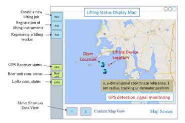
Figure 1: The surface location of ICT-based multi-communication system
Figure 2 shows a block diagram of the IoT injury motion monitoring system. The monitoring device may relay communication on a moving position and relay it to the land by LTE communication. The GPS data can then be used to track the
location of the accident.
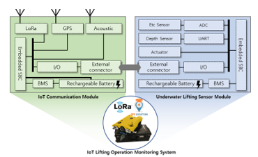
Figure 2: Block diagram of IoT behavior monitoring system
- K. Min and D. H. Yoon studied a light diffusion device in which the information transmission system can float on the water surface and light is displayed [4]. It consists of a detection unit mounted on a lifting device underwater to detect a lifting situation and a control module that converts related information into an optical signal. This study includes an optical transmission line connected to transmit the optical signal of the control module to the optical diffusion mechanism.
- H. Yoon and M. H. Park studied to provide a device and method for tracking the location of a target by continuously identifying the current location of a recovery object or rescue object such as a ship or drowning in the event of a water accident or emergency such as sinking, collision, subversion, fire, or drowning [5]. It consists of a hydraulic sensor that detects the water pressure applied to the object, a floating object separation function that separates the floating object from the object if the sensing water pressure exceeds the set value, a communication unit that communicates with the floating object, and a GPS receiver that calculates the current position.
Meanwhile, D. H. Yoon [6] developed process fusion and production automation technology based on the infusion method to produce a boat with enhanced stability. Process fusion-based boat manufacturing devices to strengthen safety analyzed the balance and center of gravity of the boat in 3D (dimension), and studied the size of the bonding area, curvature of the bonding surface, and strength of the bonding surface. Particularly, the boat manufacturing device has a function of adjusting the mixing ratio of the resin and the curing agent and adjusting the discharge amount per unit time based on the results of the joint area analysis. According to this time, it includes controlling the manufacturing process, such as width joint of the boat, makeup taping, accessory adhesion, and sealing by spraying adhesive at a set temperature according to 3D flow analysis.
Existing human lifting technology consists of zipping the instrument that holds the human body on the seabed, and most of the technologies are applied to raise the instrument by injecting air into a separate lift bag when lifting it to the surface [7, 8]. However, the integrated package set that combines roll-fold-based gas expansion technology does not show reliable performance for consumers [9]. Particularly, when diving into the water, it is subject to a lot of buoyancy resistance due to the weight and volume of the diver’s equipment, and which complains of difficulties due to the time it takes to work underwater and the complexity of the work manual.
Technology for lifting the human body underwater should not miss Golden Time in the event of a marine accident, and the safety of divers should be secured first. It is very important not only to complete the work within 30 minutes of oxygen consumption time, but also to secure underwater turbidity, underwater flow rate, and visibility. To this end, various studies are needed, including durable materials, weight reduction, structure considering flow rates, and easy-to-handle manuals. In addition, since the marine area is wider than the land area, the cost of on-site helicopters, police patrol boats, diving personnel, and on-site command centers in the event of an accident is enormous [10]. Particularly, as seen in the Ferry Sewol incident in Korea, the underwater turbidity and flow rate were very severe, making it very difficult for divers to access the sunken ship, and it was also confirmed in cases where the safety of field workers could not be guaranteed.
In this study, we develop a package-type human lifting device system in which the lifting device rises to the surface through the quantity and flow rate flowing through the lifting device, renewable materials and durable designs, and underwater shooting of CO2 cartridges. In addition, the equipment is designed by applying an air cartridge method to minimize the time spent underwater through the convenience, weight reduction, and rapid operation of rescue workers. Through this, research is conducted on securing the reliability of the rapid lifting and lifting process.
2. Implementation of GAS Dispensing Human Lifting Device
2.1. Underwater Environment
The design of the lifting device is optimized based on various underwater environment data through prototype development. Korea’s underwater environment has severe waves on the east coast, and it takes longer to darken than the bright time underwater between sunrise and sunset. In the case of the west coast, the turbidity is so serious that it is difficult to check the front 1m, and there is a risk that everyone will be exposed to safety accidents [2]. Moreover, the difference between the tides, where the sea level changes vertically twice a day every 12 hours and 25 minutes, represents 9m from the coast in Incheon and 3m from Mokpo [9]. Compared to the tidal phenomenon in which the height of seawater changes vertically, algae move horizontally, and Korea’s west coast is known to be the three most severe tidal regions in the world, along with Canada’s Pun Dee Bay and France’s Saint-Michel Bay. As such, if the vertical tidal phenomenon of seawater is severe, the horizontal tidal flow becomes fast, and marine accidents such as ship stranded occur frequently. Particularly, seawater cooled in winter begins to rise in temperature from the surface of the sea from April to May, and when seawater is mixed due to the temperature difference between the surface of the coast and the deep sea, the flow of algae increases. Frequent fog occurs due to the formation of electric wires, so caution is needed in ship navigation.
Another aspect of the underwater environment is that the bottom of the sea floor is piled up with light-type soil of tens of centimeters to tens of meters, and soil is pouring out of the Yellow River in China, making the more sea foggy. Particularly, it is very important to secure visibility in the event of a marine accident for the soil environment caused by severe turbidity and floating matter. Figure 3 shows diving activities in various underwater
environments.
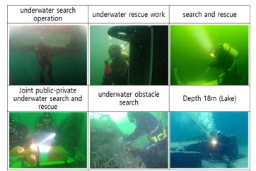
Figure 3: Diving activities in various underwater environments
In this study, depending on the worst underwater environment, the lifting device is implemented in consideration of the mesh structure, portability, weight reduction, and operability to reduce buoyancy in water. It is characterized by designing a lifting device in the form of an integrated lifting device and a surface marker Buoy (SMB), and firing a CO2 cartridge to quickly discharge it to the surface of the water. The 33g CO2 cartridge attaches two manipulators to attach two to the lifting mechanism. Until now, it is understood that no lifting net-integrated airbag has been developed yet.
The lifting mechanism utilizes the effect of rising to the surface of the water through the underwater bombardment of the CO2 cartridge. The air cartridge method was applied while requiring the portability and rapid operation of the lifting device. Therefore, research on securing the reliability of the rapid lifting and lifting process is continuing. Figure 4 compares the mesh-type lifting device designed as an early prototype with the lifting device used by the National Police Agency’s scientific investigation unit.
2.2. Design of Lifting Instruments
The lifting device design is designed in consideration of mass production through portability, convenience and simplicity of use, production cost reduction, and mold improvement, and components are designed in consideration of the efficiency and convenience of underwater work. At this time, the flow rate and quantity are calculated by applying Boyle’s law to secure the flexibility of the lifting mechanism in water. Figure 4 explains the Boyle law for the quantity and flow rate experiment flowing through the lifting mechanism. Here, d represents the length, A represents the cross-sectional area, Q represents the flow rate, represents the time taken, and is the average speed. We can explain the Figure 4 as follows an equation (1)
![]()
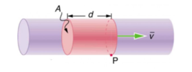
Figure 4: Designing the flow rate and quantity flowing through the lifting device
Lightweight is needed to minimize weight underwater and ease portability. The flow rate is calculated to secure flexibility as follows the equation (2).
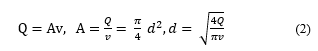
Figure 5 uses TPU, a light and renewable durable material that taking account of the quantity and flow rate flowing through the lifting mechanism. The inlet of the lifting instrument plays an important role in underwater work. In addition, it is designed with a mesh structure so that the human body and water entering the entrance exit at a high speed.
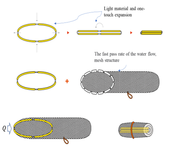
Figure 5: Detailed Design of Lifting Appliances
When the diver enters the water, the amount of oxygen in the oxygen tank is compressed, increasing the fatigue of the underwater worker. The deeper you get into the water, the more oxygen (within 30 minutes) shrinks, and the faster the work should be done in consideration of the falling time, working time, and rising time.
Figure 6 shows the operation of underwater using the designed lifting mechanism rule. Use the hook law for tensile stress and load during underwater operation. In equation (3), is tensile stress, P is load (tension), E is cross-sectional area, and is elastic coefficient.
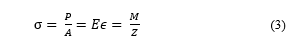
here, is the coefficient, is the silver bending moment, and represents the cross-sectional coefficient.
Use durable material TPU 80 and 95 for the bow.
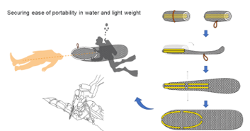
Figure 6: Underwater working behavior
In order to maintain extreme bending or the shape of the round part when combining the hinge and the bow, the occurrence of play due to elastic loss over time was minimized. The hinge connection was designed with a cross-shaped double support structure, but it was very difficult to maintain its shape due to tension loss. Therefore, it was designed with a support structure of thickness and width that gradually became thinner around the bow, and which developed into a two-piece one-stage structure. Figure 7 shows the double support structure and design for maintaining the roundness value and shape.
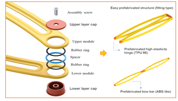
Figure 7: High elasticity hinge design and detailed schematic
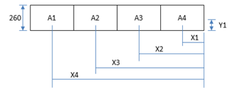
Figure 8: The lifting mechanism of network structure
When the human body is inserted into the lifting device and raised to the sea level, the weight balance technology of the network structure is applied to configure the head to face the sea level. The lifting mechanism uses a formula and Y1 = Y2 = Y3 = Y4 to design a weight-balanced algorithm for 2000x260mm SMB and network structures, which can calculate X1, X2, X3, and X4 differently. Figure 8 shows the weight balance algorithm of the lifting mechanism network structure. Figure 8 shows the lifting mechanism of network structure.
Figure 9 shows the weight balance algorithm of the lifting mechanism network structure based on figure 8.
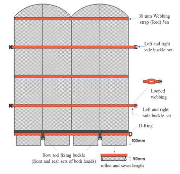
Figure 9: Weight balance algorithm of the lifting mechanism network structure
On the other hand, in water, SMB (Surface Marker Buoy) is designed in a form with a certain slope. The equation for volume and area S of SMB is as follows;
![]()
here, is the buoyancy, is the density of water and is gravity acceleration. The scientific design of the lifting mechanism take into account for the weight held when underwater and the ease of work due to underwater internal force. Particularly, after inserting a dead body into a lifting device, weight balancing technology is applied to configure the head to face the sea level. Figure 10 shows the design cases according to the length of the SMB and mesh net with a certain slope.
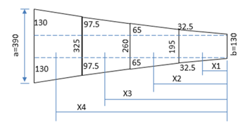
Figure 10: SMB and mesh gradient angle with constant gradient
Figure 11 shows the lifting mechanism packaged with the designed SMB and mesh network. Tightening devices were added to both sides in consideration of the expansion of the lifting mechanism. In the SMB header part, it has the pump valve, and the oral inflator are valves that take account of CO2 loss, and consist of an air inlet using the last CO2 cartridge.
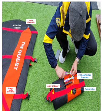
Figure 11: Lifting device packaged with a mesh net
When working at a depth of 20 → 30 → 40m each, the worker’s physical strength decreases severely due to securing time to the surface of the water and the difference in buoyancy of the human body [5]. When working in pairs, it is very important not to lose a team member. Considering that the maintenance time of the oxygen tank held by the underwater worker is 30 minutes, it takes more than 2 hours of sufficient rest time on the water surface. Figure 12 shows the folding method and size of the lifting device packaged with SMB and mesh net.
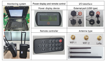
Figure 12: Folding method and size of lifting appliance packaged with SMB and mesh net
Figure 13 shows the monitoring tracking system and surrounding accessories. The monitoring system plays a very important role in securing the location of the lifting instrument and the location of underwater workers [2, 6]. The underwater ultrasonic sensor signal is supplied using a USB port, and the O/S is configured with Linux. In the commercialization stage of the lifting system, low-end type development is easy and compatibility is wide.
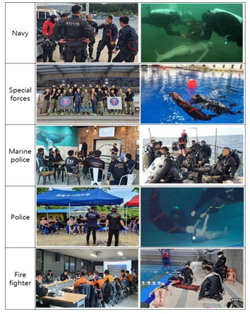
Figure 13. Monitoring position tracking system and peripheral accessories
3. Experimental Results
3.1. Experimental Scenarios
The design of the lifting device is optimized based on various underwater environment data through prototype development. Korea’s underwater environment is characterized by severe waves on the east coast, and the water quickly darkens except between sunrise and sunset. In the case of the west coast, the turbidity is so severe that it is difficult to check 1m ahead, and there is a risk that everyone will be exposed to safety accidents. Particularly, despite the difficulty of the test environment due to the tangled waste and mud, this can be explained as the worst lifting condition in the event of an accident.
The quantity and flow rate flowing through the lifting mechanism, renewable materials, and durable designs were selected. Safety and efficiency are the top priorities of the package-type human lifting system in which the lifting device rises to the surface through the underwater shooting of the CO2 cartridge. Particularly, the GAS injection method SMB was packaged with a mesh network to minimize the time spent underwater through the convenience, weight reduction, and rapid operation of rescue workers. Through this, an experiment was conducted on securing the reliability of the rapid lifting and lifting process.
When the depth of the water deepens, the diver’s decompression limit time is 8 minutes for work above 40m, and the effective air capacity of the air tank is reduced by 1/4 by water pressure. After 20→30→40m of underwater entry work, the worker’s physical strength is severely deteriorated due to the difference in buoyancy of the human body and securing time to come to the surface of the water. When working in pairs, it is very important not to lose the group due to underwater forgetting. Considering that the maintenance time of the oxygen tank held by the underwater worker is 30 minutes, it takes more than 2 hours of the sufficient rest time, Particularly, musculoskeletal diseases, mental diseases, and rheumatism that appear in divers are the reasons why sufficient rest and management are needed after underwater work. Figure 14 shows awareness of fatigue and stress that may appear after work.
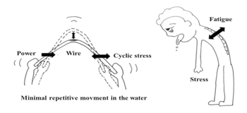
Figure 14: Awareness of fatigue and stress after work
The underwater communication test was conducted in real time from 6m to 40m in depth. The ultrasonic sound sensor is converted to 2,400bps and verifies the transmission error according to the binary. The communication speed from sensor to monitor is 115,200bps, and the communication speed from controller to receiver is 2,400bps.
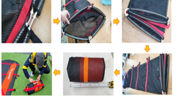
Figure 15: Performing underwater work based on various environment
In order to gain the reliability of the experiment, public-private forces (Navy, Marine Police, Fire Department, and Public Safety Submersible Association) jointly conduct underwater human lifting training and experiments. Particularly, it was based on the experience of participating in Ferry Sewol events in Korea’s West Sea (Korea Public Safety Submersible Association), and it was found that securing the safety of divers was also very important by conducting experiments based on various marine environment data. Figure 15 shows each participating organization that performs underwater work based on various environmental data, including the author. The organizations that participated in the study included naval special teams, maritime police, land police, firefighters and divers.
3.2. Lifting Appliances Experiment
Figure 16 compares the performance of each prototype with the proposal of a lifting mechanism of the rotary ring method, zipper and yelcro method, and ring cage method.
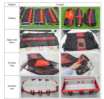
Figure 16. Comparison of the rotating ring method, zipper and Velcro method, and Linkage method
The rotating ring method of the initial prototype takes time to fasten in the rotating ring, and the weight is increased underwater using a mesh net made of plastic. In particular, it was difficult to dive more than 10m due to buoyancy when diving into the water. The zipper and Velcro method is a form of combining a straight SMB and fastening the inlet to a mesh net made of plastic with a zipper. When gas is injected into a straight SMB, it takes time because the body is not centered when it rises to the surface, and in the case of an old body, damage was feared. Lastly, the SMB integrated package bag type of the GAS injection method is a lightweight TPU 80 material and the entrance is designed for durability and flexibility.
The product used in the diving investigation department of the Korea Coast Guard requires rapid discharge due to the hops of the human body and the water accommodated through the entrance, and swells underwater, causing inconvenience in working. In order to protect the lifting device SMB, the relief valve provides a function of automatically maintaining a constant pressure by discharging air when the pressure inside the airbag increases. The water pressure corresponding to 5 atmospheric pressure is formed on the seabed surface of 40m deep, so the air capacity is reduced to 1/5 when the air cartridge is operated. When the water pressure decreases as the lifting mechanism rises, the air inside the lifting mechanism relatively increases. When the pressure or more is formed in the lifting mechanism, air is discharged through the relief valve, and the pressure is controlled. Figure 17 shows the disassembly and assembly process of the relief valve.
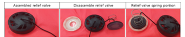
Figure 17: Disassembly and assembly of relief valves
Figure 18 shows the water surface rise of the lifting mechanism according to buoyancy and weight after injecting CO2 gas into SMB. The lifting mechanism begins to tilt according to buoyancy and weight, tilting in the vertical direction such as 16.68 for S1, 22.78 for S2, 28.40 for S3, and 33.39, and rising to the surface of the water.
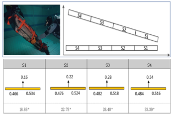
Fig. 18. Water level rise of lifting equipment according to buoyancy and weight after CO2 gas injection into SMB
Table 1 shows the underwater characteristics according to diameter, length, weight, and burst pressure according to the CO2 cartridge specification.
Table 1: Underwater data according to CO2 cartridge specification
| Vol.(cc) | Dia.(mm) | Length(mm) | weight (g) | Burst pressure (Bar) | Mouth Con. |
| 18 | 22 | 88 | 70 | 450 | No thread |
| 25 | 25 | 95 | 90 | 450 | 3/8-24 UNF |
| 32 | 25 | 107 | 105 | 450 | 1/2-20 UNF |
| 42 | 22 | 160 | 117 | 450 | No thread |
| 45 | 22 | 248 | 225 | 450 | No thread |
| 60 | 30 | 120 | 155 | 450 | 1/2-20 UNF |
| 61 | 22 | 248 | 225 | 450 | No thread |
| 95 | 40 | 138 | 275 | 450 | 5/8-18 UNF |
| 110 | 40 | 150 | 450 | 245 | M16 x 1.5 |
The buoyancy of the lifting instrument was 7-5, 9-5, rotary, and when folded, buoyancy and rising experiments were conducted. At this time, the measured weight = actual weight – was calculated as the weight of the substituted fluid, and the density / fluid density = weight / weight of the substituted fluid.
| Table 2: Buoyancy of lifting instruments | ||||||
| Type | Trans.
(m) |
Length
(m) |
Height
(m) |
Volume
(㎥) |
Buoyancy
(N) |
Decision |
| 7-5 type | 2.00 | 0.70 | 0.05 | 0.070 | 686.70 | rising |
| 9-5 type | 2.00 | 0.90 | 0.05 | 0.090 | 882.90 | rising |
| Cir. Guide | 6.00 | 3.14 | 0.03 | 0.00565 | 55.45 | rising |
| Folded type | 1.00 | 3.14 | 0.18 | 0.00565 | 55.45 | rising |
The lifting device uses a lifting device with a 4-link bridge structure as a group of two, but it was developed to enable rescue activities for one person. Particularly, the 4 -links inlet of the lifting device is designed to be easily handled by folding once after capturing the human body. In addition, a fastening device was installed to facilitate the expansion of the package that the human structures were simultaneously performed. Figure 19 shows cases such as SMB-integrated package type, SMB separation type, human lifting buoyancy experiment scene, and
three-person expansion.
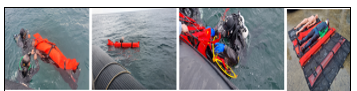
Figure 19: Experiments of SMB package, SMB detachable type, human lift buoyancy check.
Figure 20 shows that marine police and naval investigators are equipped with lifting instruments and conduct underwater experiments. Underwater gravity, underwater weight, weight of the lifting instrument, and total weight of the lifting instrument were measured for the total weight of 120 kg equipped with the equipment equipped with the diver and the lifting instrument package.
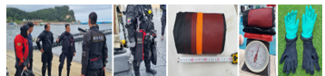
Figure 20. Underwater experiments of lifting instruments by maritime police and naval personnel
Gloves are worn to maintain the body temperature of underwater divers, but the working time may be extended due to a decrease in body temperature, and if the lifting device is complicated, it may take excessive working time.
Table 3: Total weight of underwater gravity, underwater and weight
| Weight | Gravity of the lifting object | Weight of under water(kg) | Air lifting appliance | Appliance weight
(kg) |
Total
weight (kg) |
Gravity (N) |
| 120.00 | 1.05 | 6.00 | 3.00 | 1.00 | 7.00 | 68.67 |
| 1.10 | 12.00 | 1.00 | 13.00 | 127.53 | ||
| 1.20 | 24.00 | 1.00 | 25.00 | 245.25 |
An example of experimenting is a lifting mechanism packaged with a GAS injection-type SMB and a mesh net at a depth of 40m. At this time, the season was around May, and the experiment was conducted from 10 a.m. to 12 hours. To secure an underwater view, an LED lantern was equipped, and an experiment was conducted in an environment with a good wave of 2 to 3m. The experiment was completed in a short time as the oxygen supply was reduced to 20 to 25 minutes.
Figure 21 shows the buoyancy formation, acceptable weight, underwater pressure, air injection time and buoyancy, results of the lifting mechanism in accordance with the CO2 cartridge explosion in the experiments of Table 3.
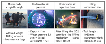
Figure 21: Flotation experiment according to CO2 GAS cartridge explosion at a depth of 40m
Underwater human lifting tests were conducted from 10:00 a.m. to 12:00 p.m. and 14:00 p.m. to 16:00 p.m. from November to December 2021, spring for a month between April and May 2022, and 30 to 40 experiments were conducted over four seasons from October to November 2022.
3.3. Experiment of a location tracking monitoring device
Figure 22 is the main screen of the monitoring device and shows the monitor layout in consideration of the environment of use, such as the lifting instrument state map, location information, and additional functions. The control system is a portable system that is convenient to move and receives sensor signals based on Linux O/S using a USB port. At this time, the temperature measurement data according to gyro, acceleration, and water depth are shown.
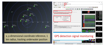
Figure 22: Lifting Status Map and Monitoring Display
Table 4: Measurement data according to gyro, acceleration, depth, and temperature
| Gyro | Acceleration | Depth of the water | Temperature | |||||
| yaw | pitch | roll | x-acc | y-acc | z-acc | |||
| 0m | 130.31 | -64.5 | 77.31 | -8.85 | -4.29 | 0.61 | -0.11 | 23.29 |
| -1m | 38.13 | -81.12 | 179.25 | -9.66 | -0.13 | -1.4 | 0.85 | 23.38 |
| -2m | 191.44 | -82.56 | -172.13 | -9.69 | 0.07 | -1.36 | 1.94 | 23.49 |
| -3m | 97.56 | -83.19 | 179.19 | -9.71 | -0.19 | -1.15 | 2.96 | 23.54 |
| -4m | 10.81 | -82.94 | 166.56 | -9.75 | -0.28 | -1.03 | 3.93 | 23.58 |
| -5m | 87.69 | -84.25 | 177.5 | -9.78 | -0.45 | -0.9 | 4.93 | 23.63 |
| -6m | 252.63 | 0.37 | -119.31 | 0.05 | 8.54 | -4.61 | 5.63 | 23.63 |
Figure 23 shows the results of experiments on the communication distance and communication speed between the monitoring device and the underwater transmitter located on land and sea.
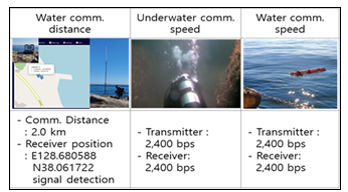
Figure 23: Experiments on the communication distance and speed of the monitoring device
The control monitoring device is portable and receives a sensor signal using a USB port. It can be configured with Linux O/S to provide a wide range of compatibility.
4. Conclusion
In the event of an underwater accident in the ocean or land, this study efficiently lifted the human body and implemented a gas injection-type prefabricated lifting device based on location tracking. To secure golden time and the safety of divers, the efficiency and safety of the lifting system were considered as the top priority for saving lives underwater.
At 40 m underwater, divers must endure up to 30 minutes with two air cylinders, and the worst underwater experimental environment conditions such as securing visibility and dangerous environments with high flow rates were selected due to underwater turbidity. Particularly, there are many cases where life is threatened by hypothermia in the water. Therefore, both divers and the deceased need location tracking connected to the lifting device, and a fast and efficient lifting system was studied in underwater activities.
The gas injection-type prefabricated lifting device with a high elastic structure is lightweight and portable, and a baggy bag is composed of minimal components to increase the use method and work efficiency based on the instinctive behavior of the diver. Accordingly, the entrance element design combining a bow and hinge that maintains a moment of force with TPU-based materials, the balance design using weight balancing technology of the network structure, the SMB linkage design that induces water surface rise through gas injection, and the entire assembly were tested underwater.
Coast Guard, special investigators, and fire officials participated to improve reliability by using a situation where turbidity was an very high and the flow rate of underwater sites was high as the worst field experiment conditions. Due to turbidity, the West Coast’s two-person rescue experiment was also exposed to safety accidents, and the study was conducted in a way that auxiliary diving personnel performed guard duties in preparation for safety accidents.
As the water pressure increased by 1 atmosphere every 10m deep, the amount of air in the lifting appliance was compressed to 1/2 compared to the land, and it was found that using one CO2 cartridge for 60kg underwater mannequin sufficiently reached the surface of the water.
When the water depth decreases in the process of the lifting instrument rising from the seabed to the surface of the water, the water pressure decreases at the same time. At this time, the air inside the lifting device expands and the pressure rises, and as it reaches the water surface, the pressure control valve attached to the lifting device operates to discharge air and maintain constant pressure. When 38g of the CO2 cartridge was injected at a depth of 40m, it took about 10sec for the water lift to start, and at the same time as lifting the human body, a manual for securing the safety of the diving source could be established.
At 40m underwater, water depth, water temperature, and direction angle were transmitted to rescue personnel on the water surface as a location detection signal through monitoring and the start of water rise of the lifting device. At a depth of 40m, the lifting test calculated the diving agent’s acquisition time, working time, and time taken to get out, considering the oxygen content of about 30 minutes. At this time, the time available for work was as short as eight minutes.
The location tracking monitoring device of the lifting device was implemented in consideration of underwater lifting situation information storage, display, and waterproof functions. LTE technology for short-range and long-distance communication was applied to the acoustic sensors obtained underwater, and interface functions were expanded through USB ports. In the future, we will focus on portability, weight reduction, low battery power, and extended life time.
- J. H. Yoon, D. H. Yoon, “A Human Lifting and Navigation System Based on ICT for Underwater Rescue,” 2022 The 22nd International Conference on Control, Automation and Systems (ICCAS 2022) BEXCO, Busan, Korea, Nov. 27~Dec. 2022
- J. H. Yoon, S. I. Kang, D. H. Yoon, “Implementation of ICT-based Underwater Communication Monitoring Device for Underwater Lifting,” Institute of Korean Electrical and Electronics Engineers (IKEEE), 26(3), 396~400, 2022
- D. H. Yoon, “Location Tracking Apparatus and Method in Water Accident or Emergency Situation,” Patents No.10-2020-0142370, Sept. 2020
- H. K. Min, D. H. Yoon et al, “Information Transmission System of Lifting Apparatus” Patents No.10-2020-0127360, 2020
- D. H. Yoon, M. H. Park, “Water Accident Emergency Response System and Method Thereof”, Patents 10-2020-0126397, 2020
- D. H. Yoon, “Boat Aerostat Production Apparatus and Method for Safety Strengthen Based on Manufacture Convergence,” Patents No.10-2020-0137878, 2020
- Science and Technology, “System Assessment and Validation for Emergency Responders (SAVER),” U.S. Department of Homeland Security, 2021
- Central Maritime Safety Tribuna, “Announcement of Maritime Accident Statistics in 2021”
- H. K. Min, N. H. Seong, et al, “Development of ICT-based human body lifting system for underwater structures”, Techinical Report, Ministry of SMEs and Startups, 2021
- J. G. Kim, “The Design and Implementation of Seabed Auto-interpretation System Using Ultrasonic Signal Processing”, 2001