
Design of Bio-Inspired Robot Hand Using Multiple Types of Actuators
Volume 8, Issue 6, Page No 65-77, 2023
Author’s Name: Traithep Wimonrut, Jittaboon Trichada, Narongsak Tirasuntarakula), Eakkachai Pengwang
View Affiliations
Institute of Field Robotics, King Mongkut’s University of Technology Thonburi, Bangkok, 10140, Thailand
a)whom correspondence should be addressed. E-mail: narongsak.tir@kmutt.ac.th
Adv. Sci. Technol. Eng. Syst. J. 8(6), 65-77 (2023); ![]() DOI: 10.25046/aj080608
DOI: 10.25046/aj080608
Keywords: Robotics hand, Multiple types of actuators, Hand gestures

Export Citations
Many prosthetic hands are focused on appearance and grip strength, however, gestures are also one of the performances that users need for communicating with others as body language to express their feeling and intention. For this paper, the initial prototype of the gesturing robotics hand is presented by using multiple types of actuators concept to maintain its appearance while the number of degrees of freedom (DOFs) is increased. The gesture performance of this robotic hand is improved by designing 2 DOFs in each finger; therefore, the entire hand has 15 joints, 10 DOFs, and one controllable wrist joint. In the detail of the design, all actuating mechanisms of 3 joints for each finger are specifically designed to maintain the human limb appearance. The Distal Phalange joint (DIP) used a linkage mechanism to acquire the Proximal Phalange joint’s (PIP) movement by a 1:0.961 ratio due to appearance designed. The PIP joint is built with a cable-drive mechanism powered by a digital servo motor installed in the forearm. The Metacarpal joint (MCP) is driven by a micro linear actuator in the hand palm. A micro linear actuator was also selected to drive the wrist of the robot. The hand can perform 10 hand gestures follow common emoji hand gestures and holding 12 objects in the hand. The design of this bio inspired robot hand can be downloaded for educational purpose.
Received: 14 August 2023, Accepted: 14 November 2023, Published Online: 30 November 2023
1. Introduction
This paper has been developed from “Design of an Open-Source Anthropomorphic Robotic Finger for Telepresence Robot” [1] to become a hand and forearm. As a big picture of the project is to develop the telepresence robot that can present the human feeling between the operator who controls a robot and participant who interactives with robot. From the study and research of various types of robotic hands, it can be divided into two major developments. The first is a robotic hand that was developed for the articulate arms, which focus on the performance to pick up objects in different ways. Generally, a number of controllable hands joints is more or equal to the number of human hands. However, the appearance is not a focus point for this type, for example, “The DLR hand arm system” [2], “Shadow Dexterous Hand E1 Series” [3], and many of the robotics hands in “A Review of Anthropomorphic Robotic Hand Technology and Data Glove Based Control” paper [4]. The second is robotic hands used for
disabilities people also known as prosthetic hands. Most prosthetic hands have appearances like human beings. However, the number of controllable joints that is reduced to 5 DOFs for 1 hand such as “Dextrus V2.0” [5], “Limbitless” [5], or even reduce the moveable joint such as “Michelangelo Hand” [6] in order to reduce the volume and suitable for users. In many cases, a hand gesture for the prosthetic hands can be created with just an open bare hand and the grip for the fist posture. Some prosthetic hand has 2 joints in each finger which is Metacarpo Phalangeal Joint (MCP) as a drive joint, Proximal Interphalangeal Joint (PIP) as an under actuated joint, and Distal Interphalangeal Joint (DIP) Joint as a fixed joint. Each finger can be controlled by 1 or 2 actuators like a “Prosthetic hand from Touch Bionics” [7], and “Bebionic Prosthetic Hand” [8] which has been developed up to present. Researchers intend to design a prototype of robotic hand that has an appearance like a prosthetic hand to keep the participant feeling like communicating with human while remaining a controllable joint as a robotics hand for the operator to have a controllable joint equally to the human hand joint. As a result, In the constrained appearance, the hand has more natural movement more than normal prosthetic hands with 2 actuated joint drives and 1 under actuated linkage joint. This hand can be used to communicate by using a common hand sign to express the meaning of the operator and also has the capacity to hold daily used objects. The prototype hand as shown in Figure 1. It is mostly built from a 3D printer. The researcher intends to share this 3D model with those who are interested in further development.
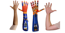
Figure 1: Hand and Forearm Compared Between Robot and Dorsal Side (Left) and Ventral Side (Right).
2. Design Methodology
Given the significance of appearance, the design prioritized size considerations. The hand, along with the forearm, was segmented into seven main components, namely the fingers, palm, metacarpal thumb, wrist, forearm, Dynamixel box, and cover plate, as shown in Figure 2. The dimensions and specifics of each part are detailed below.
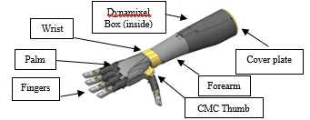
Figure 2: 3D Model of Robotics Hand and Forearm.
2.1. Fingers
The initial finger design utilized cables to control joint movement, with 10 rotary actuators located in the forearm, each dedicated to a specific joint. To flex or extend the PIP joint, tension is applied to the tendons linked to the DIP joint. This transmits force through the linkage, coordinating the movement of both joints. The tendon path from the actuator to the DIP joint passes through the PIP joint. The upper path extends the PIP joint, while the lower path flexes the PIP joint. However, for the tendon to pass through the upper part of the PIP joint, the linkage must have a cavity in its middle, potentially reducing its strength, as shown in Figure 3.
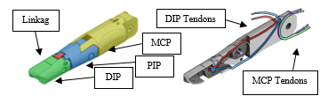
Figure 3: Initial Finger Design.
To improve the appearance of the forearm and create a more natural arm-like shape, modifications were made to the finger design. Specifically, the MCP joint was modified from a cable drive to support a linear actuator hinge drive. This refinement allowed for the preservation of five rotary actuators for cable drive, while the remaining five rotary actuators were replaced with linear actuators directly connected to their respective joints. Furthermore, the original 4-bar linkage system in the middle of the finger was reconfigured to a dual linkage system. In this design, the center axis of the Proximal Interphalangeal joint (PIP) is redesigned as a circular channel to support the tendon traction with a constant radius as shown in Figure 4.
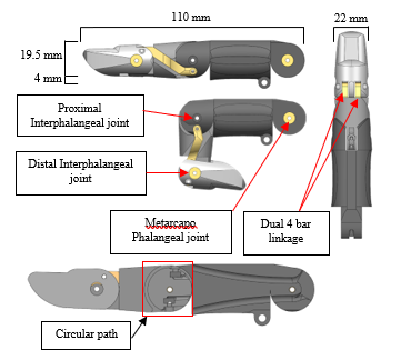
Figure 4: 3D Model Finger
Thumb, Index, Middle, Ring, and Little fingers use the same models for convenience of maintenance and to reduce the time of printing parts. The MCP joints of the Index, Middle, Ring, and Little fingers are attached with linear actuator PQ12-R 30:1 gear ratio with 20 mm stroke. When fully extended, these joints align with the palm, whereas when the linear actuator is completely retracted, the MCP joint flexes down to an angle of 77.59 degrees. This angle arises due to the position of the cylinder upon retraction. The linear actuator is designed to ensure that it fits as closely as possible to the palm, thus enabling convenient attachment via screwing. as shown in Figure 5.
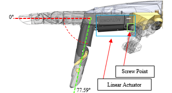
Figure 5: Range of Motion MCP joint.
The thrusting position of the linear actuator is perpendicular to the pivot point at a radius of 10.75 mm when the fingers are in the most folded position towards the palm. When the fingers are unfolded, the distance between the thrusting position and the pivot point is 14.11 mm as shown in Figure 6.
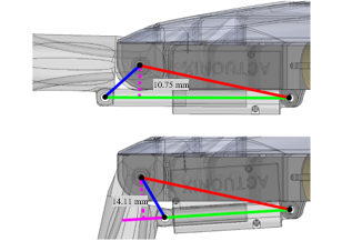
Figure 6: Extended MCP Joint (Top) and Flexed MCP Joint (Bottom)
The PIP joint is actuated by two of 4 braid PE fiber lines which have a thickness of 0.26 mm that provide flexibility in bending and can withstand a maximum tensile force of 13.6 KG. as tendons for flexion and extension, respectively. The metacarpal bone features two distinct paths for these tendons, namely the upper and lower paths. The flexion tendon travels through the lower path before turning up towards the top and securing with a screw, as illustrated in Figure 6. In contrast, the extension tendon travels through the upper path before turning down towards the bottom and fastening with a screw, as shown in Figure 7-8.
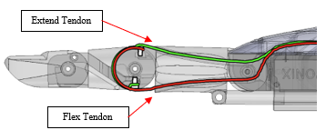
Figure 7: Flex Tendon (Bottom) and Extend Tendon (Top)
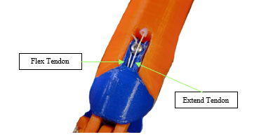
Figure 8: Flex Tendon Screw on Top of The PIP joint.
By focusing on the external appearance, the lengths of each joint are shown in Table 1. These values are substituted back in the equation to solve for the θ3. The result is the ratio of turning the PIP and DIP joints will be 1:0.961. While turning the PIP joint 90 degrees, the DIP joint will rotate 86.5 degrees as shown in Figure 9.
Table 1: Values of Finger
| Finger Parts | Variable | Value | Unit |
| Middle Phalanx (Middle) | l2 | 28 | mm |
| Distal Phalanx (Distal) | l3 | 26.5 | mm |
| Proximal interphalangeal joint Four-bar radius | r2 | 5.5 | mm |
| Distal interphalangeal joint Four-bar radius | r3 | 5.5 | mm |
| Degree between Proximal Phalanx and Proximal inter phalangeal Four-bar | α2 | 180 | Degree |
| Standard degree between Middle Phalanx and Distal interphalangeal joint Four-bar | α3 | 60 | Degree |
| Moving degree of Proximal phalangeal joint | θ2 | 90 | Degree |
| Moving degree of Distal phalangeal joint | θ3 | Result | Degree |
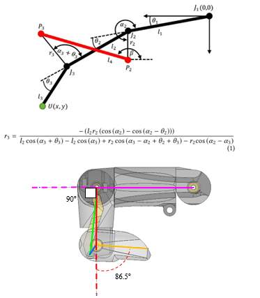
Figure 9: Annotations for Finger Dimension, Calculation, and the Relative Degree Between DIP and PIP.
2.2. Palm
The palmar side of the hand is equipped with five linear actuators, with the middle finger serving as the reference axis for the index and ring fingers. These fingers are separated at an angle of 5 degrees from the adjacent finger as shown in Figure 10. The thumb, however, requires special attention in order to mimic the palm line pattern, as shown in Figure 10. To create a rotation axis for the Carpometacarpal joint (CMC), the axis of the Middle finger crossing over the edge of the wrist and the horizontal axis of the Little finger crossing the edge of the palm at the pointer finger side remains the same. A straight line is then drawn between these two points to create a rotation axis for the Carpometacarpal joint (CMC), as shown in Figure 11.
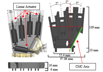
Figure 10: 3D Model of Palm
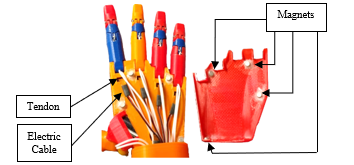
Figure 11: Reference for Palm Line Pattern.
The dorsal side of the hand is designed to accommodate the tendons and electric cables. The back of the palm is covered with a shell that has magnets, enabling quick removal for repair and maintenance, as shown in Figure 11.
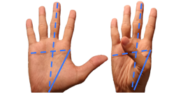
Figure 11: Dorsal Side of Palm
2.3. Carpometacarpal Joint
The Carpometacarpal (CMC) joint is the first joint of the thumb. It is driven by a single linear actuator for abduction. The extension is fixed at a 62.59° angle to improve grasping ability. This is capable of having 12° of pre-abduction and 42° of radial movement [9], [10], as shown in Figure 12.
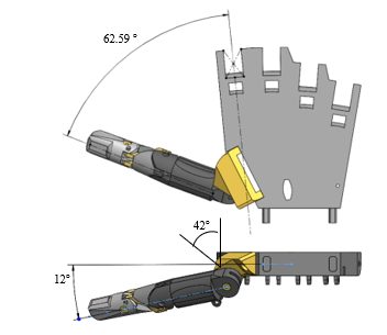
Figure 12: CMC Joint Extended Position Dorsal View (Top) and Wrist View (Bottom)
Since the space in the palm is limited by other MCP joints, the axis of CMC joints is not parallel to the linear actuator. To solve this problem, a ball joint is attached to convert the rotation axis of the CMC joint to the linear actuator axis as shown in Figure 13. The direction of force exerted by the linear actuator through the ball joint during both flexion and extension is indicated in Figure 14, with the arrow indicating the direction of force.
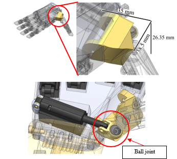
Figure 13: CMC Joint Normal Position
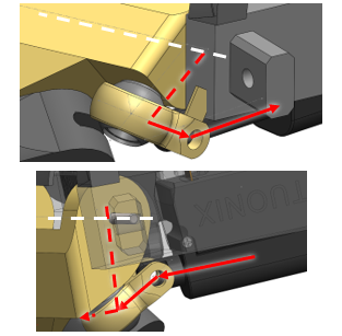
Figure 14: Extended CMC joint (Top) and Flexed CMC joint (Bottom)
The Carpometacarpal (CMC) joint, which cooperates with the ball joint, is responsible for the rotation angle of the non-parallel joint of the thumb. The rotation angle ranges from maximum extension to maximum flexion is 72 degrees, as shown in Figure 15.
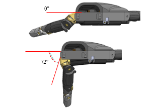
Figure 15: Range of Motion CMC joint
2.4. Wrist
The human wrist is not always in a straight position and requires mimicry to replicate natural postures. Additionally, the wrist is responsible for organizing tendons around the rotational axis to prevent any unnecessary stretch when it is flexed. The wrist itself has two distinct sides. The front side contains two sockets for attaching the hand to the bottom row, while the middle row has ten holes for tendon routing. The top row contains a single hole for the electric cable from the linear actuator. On the other side, the back side of the wrist has a rotation joint at the middle row, positioned at the same level as the tendons row, to prevent any tendon extension from the wrist’s flexion and ensure smooth tendon movement as shown in Figure 16. A separate frictionless tube is used for each of the ten tendons as shown in Figure 17. The extension from the proximal finger to the tendon holder is within the proximal forearm. Finally, the bottom row contains a hinge for the linear actuator to actuate the wrist’s flexion and extension. The design of the wrist is shown in Figure 18..
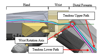
Figure 16: Tendons Path Side View
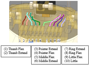
Figure 17: Tendons Path from Wrist to Forearm
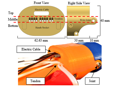
Figure 18: Wrist
The linear actuator is installed and aligned with the underarm area. The arm and wrist are designed to lie in parallel when it is fully extended. Conversely, when the linear actuator is fully retracted, the wrist is angled downwards by 50 degrees as shown in Figure 19-20. The technical specifications for linear actuators for all joints are shown in Table 2.
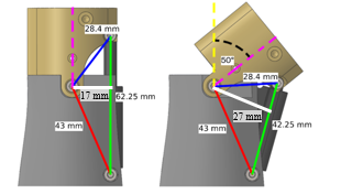
Figure 19: Wrist length parameter
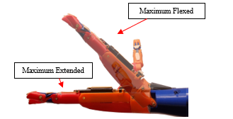
Figure 20: Robot Hand side view when flex and extend wrist.
Table 2: Specifications of Linear Actuator.
| Actuator | Actuonix PQ12-R 30:1 | Actuonix PQ12-R 63:1 |
| Joint | MCP/CMC | Wrist |
| Torque / Forces | 18 N | 45 N |
| Voltage | 6 V | 6 V |
| Stall Current | 550 mA | 550 mA |
| Dimensions (mm) (W × H × L) |
21.5 × 15 × 48(+20) | |
2.5. Forearm
The forearm is designed to resemble the anatomical structure of the human arm, with emphasis on its external appearance, as shown in Figure 21. The dimensions of the forearm are averaged values for an adult male forearm, measuring 263 mm in length, 97 mm in width at the elbow side, 64.75 mm in width at the wrist side, 75 mm in height at the elbow side, 40 mm in height at the wrist side [11].
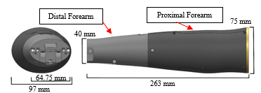
Figure 21: Forearm
The forearm is separated into two sections, namely the proximal and distal forearms as shown in Figure 22. The distal forearm is the location where the linear actuator for the wrist is attached, and it also provides a passage for wires from the internal to the external of the forearm. In addition, the distal forearm serves as the pathway for tendons to the proximal forearm, which contains the Dynamixel box as shown in Figure 23.
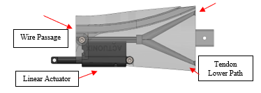
Figure 22: Distal Forearm
The Dynamixel box integrates all five Dynamixel XL430- W250-T with their tendon holders. The Dynamixel components are arranged in three rows, consisting of one unit, two units, and two units respectively. Rows 1 and 3 are oriented with heads up, while Row 2 is inverted to prevent tendons from overlapping with Row 3 as shown in Figure 24. At the end of the box, a base with a socket is installed for connection to the cover plate. The technical specifications for Dynamixel actuators for all joints are shown in Table 3.
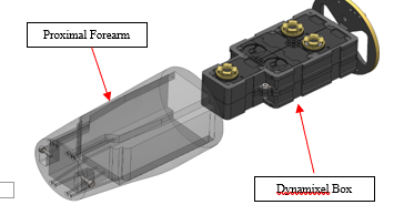
Figure 23: Proximal Forearm
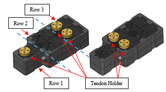
Figure 24: Dynamixel Box Upside (Left) and Downside (Right)
Table 3: Specifications of Linear Actuator.
| Actuator | Dynamixel XL-430-W250-T |
| Joint | PIP |
| Torque / Forces | 1.4 N⋅m |
| Voltage | 11.1 V |
| Stall Current | 1.3 A |
|
Dimensions (mm) (W × H × L) |
28.5 × 46.5 × 34 |
The tendon holder is composed of three parts, namely the top part, middle part, and bottom part. These parts are stacked into three layers to prevent binding between tendons. The bottom part is screwed to the Dynamixel flange, and the flex tendon is tied around it for 1 + 1/4 rounds counterclockwise. The middle part is used to extend the tendon and is tied clockwise around the part for 1 + 1/4 rounds. The top part is designed to prevent the extend tendon from coming off the circular and merging of the three parts together by using four screws as shown in Figure 25. When flex and extend tendons are tied around the tendon holder, they share the same binding point. As the Dynamixel rotates either clockwise or counterclockwise, one of the tendons will be released from the holder, while the other is wound around it at an equal distance. The radius of the tendon holder is designed to match that of the tendon binding around the proximal interphalangeal (PIP) joint. This design ensures that the rotation of the Dynamixel and the rotation of the PIP joint are synchronized and occur at the same rate. Ten tendons that have been threaded through the frictionless tube are responsible for pulling the Dynamixel box inward, ensuring that it remains securely in place within the arm as shown in Figure 26.
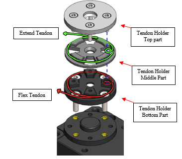
Figure 25: The layer of Tendon holder with flex tendon and extend tendon.
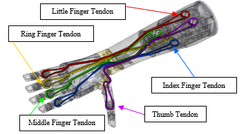
Figure 26: Overview of Tendons Routing.
Last, the cover plate encloses the proximal forearm and maintains tension in all ten tendons by securing it to the Dynamixel box. It is screwed in place to pull the Dynamixel box outward and straighten the tendons as shown in Figure 27.
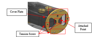
Figure 27: Cover plate.
To increase the degrees of freedom (DOFs) while maintaining the appearance of the hand and arm, multiple types of actuators were utilized within space constraints. Specifically, five linear actuators were implemented in the palm to control the MCP joints of the Index, Middle, Ring, and Little fingers, as well as the CMC joint of the thumb. The PIP joints of the Index, Middle, Ring, and Little fingers were controlled by Dynamixel digital servo motors through tendons, similar to the MCP joint of the thumb, which was also controlled by a servo motor connected through a tendon from the back of the forearm as illustrated in Figure 28. As a result of this design, the fingers can flex and extend the PIP, MCP, and CMC joints separately as shown in Figure 29.
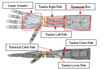
Figure 28: Inside the hand and arm.
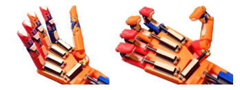
Figure 29: Robot Hand flexing a MCP (Left) and PIP (Right) joint.
3. Evaluation
Generating Gestures
Basic perform of the hand is hand signs that are formed in many postures with different meanings. However, some hand signs are widely used, such as the emoji hand sign. The emoji hand sign is widely used in various social media. The meaning may deviate, depending on the context of communication between the speakers, but the hand sign has a stable shape. Having an independent DIP and PIP joint from the MCP and CMC joint. Hence, the posture that performs a straight finger can be more realistic than the fixed DIP finger. Ten emoji hands, as shown in Table 4 and Figure 30, are an emoji that uses one hand to perform.
Table 4: Hand Sign and Meaning
| No. | Name | Meaning |
| 1 | Raised Hand |
Stop, Hello (greeting), Hi-Five (greeting) |
| 2 | I Love You | Love or Affection |
| 3 | Sign of Horns |
Rock Music Joy |
| 4 |
Raised Fist
|
Unity Resistance |
| 5 | OK | It is fine. |
| 6 | Call Me |
Call me via phone. Call me later. Take it easy |
| 7 | Thumbs Up |
Like Yes Agree Understand |
| 8 |
Backhand Index Pointing Right |
Refer attention to the things that fingertip pointed. |
| 9 | Index Pointing Up |
Contemplation Be careful |
| 10 | Victory |
Victory Peace |
More explanations for emoji and hand signs are discussed in the following section.
1) “Raised Hand” signifies that all fingers are maximum extended into a straight finger. It means “Stop”, “Hello”, or “Hi-five”.
2) “I Love You Hand Sign” is a sign with the Little finger, Index finger, and Thumb extended straight and flexed Middle finger and Ring finger into the palm. It is used to express love to the interlocutor.
3) “Sign of the Horns” looks like the “I love you hand sign” but have a flexion of the Thumb in the palm. This sign has many meanings, but in common, it is known as “The symbol of rock music, and “joy”
4) “Raised Fist” is depicted by flexing of all fingers into the palm while leaving a flexed Thumb outside the Index finger. Performing the “Raised fist” with the back to the performer can mean “Unity” or “resistance”. Front view of the fist emoji is called the “Fisted Hand Sign”, which means punching somebody. While “Left-Facing Fist” and “Right-Facing Fist” are used together to depict a friendly greeting, like giving a High-Five.
5) “OK Sign” is the sign with a flexed thumb tip and index fingertip to touch each other and leave the Middle finger, Ring finger, and Little finger straight or in a neutral finger position. The meaning of “OK” is simply well-known as “It is fine.” to the situation.
6) “Call Me” is the sign with an extended Thumb and Little finger straight and flexed Index finger, Middle finger, and Little finger into the palm. It is used to express the meaning of “Call me”.
7) “Thumbs Up Sign” as the flex Index finger, Middle finger, Ring finger, and Little finger into the palm and extend the Thumb straight. The “Thumbs Up” gesture is popular on social media for a meaning of positive expression, such as “Like” when the person approves of the content in the post, meaning “Yes” when the person replies to a question about a situation of something which result is come out positive way, “Agree” when the person acknowledge on the mention, and “Understand” when the person realizes clearly. On the other hand, the “Thumbs Down sign” which have the same finger posture but rotates the arm to put the Thumb downward to the ground, which means “Dislike”.
8) ” Backhand Index Pointing Right” is the posture that flexes the Little finger, Ring finger, and Middle finger into the palm, leaving the Index finger extended straight. The Thumb is extended straight or flexed to the palm.
9) “Left Pointing.”, “Down Pointing” and “Up Pointing” mean paying attention to something. Special for “Up Pointing” can be for “Think’ and “Be careful”.
10) “Victory Hand” is the sign with the Index finger and Middle finger extended straight and flexed the Little finger, Ring finger, and Thumb to the palm. and it can represent the Latin letter V which means “Victory”.
3.1. Generation of grips for holding objects
In addition to expressing the meaning through the hand sign, holding objects is another way to tell the listener what the operator’s intention is.
The objects that were selected to test are the daily use object, which comes in different shape, size, and weight [12] as shown in Table 5 and Figure 29. The object is put in the hand and the hand starts to grasp and hold still, before recording the picture. Various holding techniques are employed for different objects during grasping tasks. For instance, the Lateral Pinch grip, as demonstrated in Figure 31(1), is used for holding small flat objects like coins, card keys, and banknotes. The Tripod Pinch, depicted in Figure 31(2), is utilized for holding stick-type objects like pens and soldering irons, where three fingers are used to pin the object in position. The Cylindrical Grip, shown in Figure 31(3-6), is used to entwine cylindrical objects like soda cans, water bottles, hand drills, cleaning sprays, and sanitizer sprays. The Sticky Tape grip, illustrated in Figure 31(7), is used for holding flat cylindrical and spherical objects. The Storage Box grip, as depicted in Figure 31(8), is achieved by using only the Proximal Interphalangeal (PIP) and Distal Interphalangeal (DIP) joints to grasp and hold objects such as document files and books. In contrast, the Claw grip, illustrated in Figure 31(12), is used for holding tote bags and is performed by pointing the hand toward the ground. The Platform Posture grip, as shown in Figure 31(9), involves extending the hand with the palm side up and placing the object on top, then flexing the fingers to support the object. Lastly, the Mouse grip, depicted in Figure 31(10), is a special grip for holding a computer mouse, where the thumb, ring finger, and palm are used to set the position, and the index and middle fingers are used for left and right-clicking, respectively.

Figure 30: Robot Hand compared to the Facebook Emoji Hand.
Table 5: Object details for Figure 31.
| No. | Object | Dimension (mm) | Weight (g) |
Holding Type |
| 1 | Coin | 1.8(h) × 24(Ø) | 6 | Lateral Pinch |
| 2 | Pen | 124(h) × 12(Ø) | 7 | Tripod Pinch |
| 3 | Cleaning spray bottle | 39(l) × 34(w) 57(l) × 34(w) (trigger) |
60 | Cylindrical Grip with Trigger |
| 4 | Sanitizer spray bottle | 119(h) × 31(Ø) | 23 | Cylindrical with Extend Index Finger |
| 5 | Soda can | 150(h) × 57(Ø) | 13 | Cylindrical Grip |
| 6 | Water bottle | 177.5(h) × 57.4 (Ø) | 193 | Cylindrical Grip |
| 7 | Sticky tape | 16(h) × 55.5(Ø) | 24 | Spherical Grip |
| 8 | Storage box | 162.5(l) × 52(w) ×15.3(h) | 48 | Claw Grip |
| 9 | Plate | 120 – 230(Ø) × 34(h) | 176 | Platform |
| 10 | Mouse | 127(l) × 67(w) × 37(h) | 73 | Fingertip Grip |
| 11 | Hand | – | – | Handshake |
| 12 | Canvas Tote Bag |
28(w) × 3(h) (handle) |
129
|
Hook
|
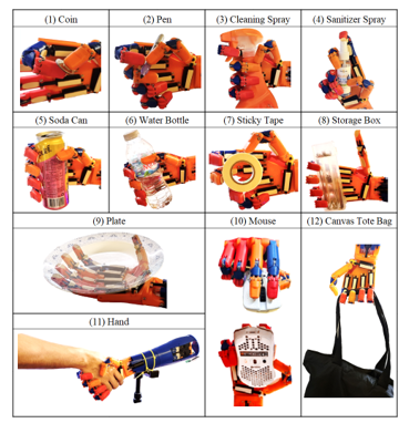
Figure 31: Robot Hand when grasped and hold the objects.
Table 6: Equation of Linear actuator.
| Fingers | Joint | Equation |
| Thumb | CMC | y = 0.07223 x – 72.23 |
| Index | y = 0.07759 x – 77.59 | |
| Middle | MCP | |
| Ring | ||
| Little |
For measuring the angle of a joint using a linear actuator, the actuator is driven by Pulse Width Modulation (PWM). A pulse width of 1000 µs results in the maximum retract stroke, while a pulse width of 1500 µs results in a 10 mm stroke, and a pulse width of 2000 µs results in a maximum extended 20 mm stroke. A linear relationship between pulse width and stroke length can be observed. By mounting the linear actuator directly on the proximal part of the finger, the measurement of the joint angle can be obtained from the pulse width of the input, which is then compared to the angle of joint rotation. An equation for determining the angle of joint flexion is provided in Table 6.
For the Dynamixel joints, values of joints can be obtained from the sensors for each joint. Due to the transmission of power through tendons that may stretch or slack over time, the flex sensor 2.2-inch is used to measure the amount of voltage in digital to compare with the actual motion (Figure 32). The measurements were subdivided into 5-degree angles and the total value was recorded 20 times per angle by fixing the joints of the fingers with the angle measuring tools. and measure the resistance at the angle, as shown in Figure 33. Measurement begins by stabilizing the PIP joint and fixing the DIP joint at 0 degrees. Record the Sensor value, then increment the DIP lock point to 5 degrees. Continue this process until reaching 85 degrees, then return to the starting position at 0 degrees. Repeat this cycle 20 times for all five fingers. After obtaining the recording table, calculate the average value for each degree before creating a graph. The goal is to derive an equation suitable for the graph, as illustrated in Figure 34-38 and Table 9. Utilizing the Flex Sensor for feedback, the calculated reading value is employed in an equation to determine the degree of joint rotation. The accuracy of angle deviation is consistently maintained within an acceptable range of plus or minus 4 degrees, ensuring minimal deviation from normal postures. Flexible sensors exhibit various resistance ranges along different sensors. When used in a 5V pull-up circuit with 220k Ω resistor, the resistance readings decrease when the sensors are bent further specification of flex sensor are shown in Table 7. Dynamixel joint has an actual maximum movement only 85 degrees, because of the guide tube in this design interrupts the movement. The details of the equation are shown in Table 8.
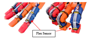
Figure 32: Flex Sensor on Fingers.
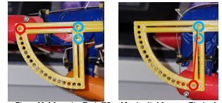
Figure 33: Measuring Tools When Not Applied Screw to Fix Angle.
Table 7: Flex Sensor Resistance Value.
| Fingers | Minimum Resistance (kΩ) |
Flat Resistance (kΩ) |
Maximum Resistance (kΩ) |
| Thumb | 40 | 440 | 720 |
| Index | 31 | 260 | 470 |
| Middle | 30 | 360 | 640 |
| Ring | 36 | 340 | 580 |
| Little | 43 | 560 | 970 |
Table 8: Equation of Dynamixel.
| Fingers | Equation | R-Square | Residual SD |
| Thumb | y = 0.0165x2 – 3.4230x + 599.7518 | 0.9900 | 5.6890 |
| Index | y = 0.0166x2 – 3.1108x + 417.6042 | 0.9912 | 4.5224 |
| Middle | y = 0.0165x2 – 4.9180x + 502.2505 | 0.9970 | 5.3356 |
| Ring | y = 0.0196x2 – 4.5638x + 505.1175 | 0.9993 | 2.1901 |
| Little | y = 0.0047x2 – 3.4375x + 629.5187 | 0.9977 | 4.0386 |
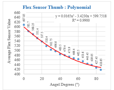
Figure 34: Flex Sensor on Thumb Finger.
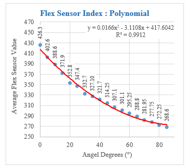
Figure 35: Flex Sensor on Index Finger.
Because of feedback from the sensor, gestures and object-holding positions can be recorded and utilized for subsequent replays without the need for the actual object to be present. This allows for the replication of movements, such as drinking water from a water can, in a simulated situation.
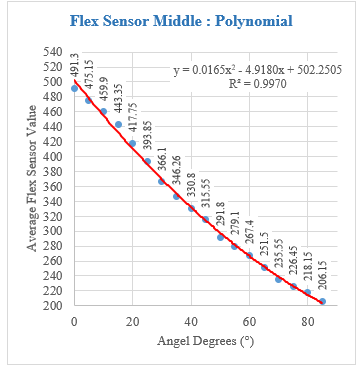
Figure 36: Flex Sensor on Middle Finger.
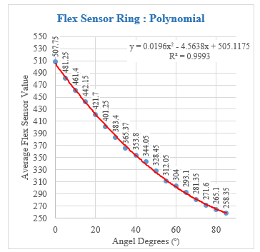
Figure 37: Flex Sensor on Ring Finger.
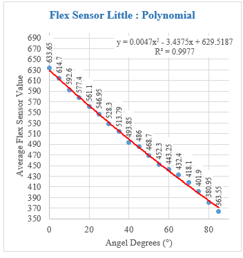
Figure 38: Flex Sensor on Little Finger.
Table 9: Flex Sensor Resistance Value.
| Average Resistance Value | ||||||||||
|
Fingers /Deg |
Thumb | SD | Pointer | SD | Middle | SD | Ring | SD | Little | SD |
| 0 | 599.8 | 3.3 | 417.6 | 3.5 | 502.3 | 3.7 | 505.1 | 2.7 | 629.5 | 2.6 |
| 5 | 583.0 | 3.0 | 402.5 | 5.0 | 478.1 | 4.7 | 482.8 | 3.0 | 612.4 | 2.4 |
| 10 | 567.2 | 3.7 | 388.2 | 5.2 | 454.7 | 3.9 | 461.4 | 3.8 | 595.6 | 2.5 |
| 15 | 552.1 | 3.5 | 374.7 | 5.1 | 432.2 | 4.9 | 441.1 | 4.8 | 579.0 | 3.4 |
| 20 | 537.9 | 3.4 | 362.0 | 4.9 | 410.5 | 2.9 | 421.7 | 3.8 | 562.6 | 3.4 |
| 25 | 524.5 | 5.4 | 350.2 | 4.0 | 389.6 | 5.1 | 403.3 | 4.2 | 546.5 | 3.8 |
| 30 | 511.9 | 4.2 | 339.2 | 2.9 | 369.6 | 3.4 | 385.8 | 3.5 | 530.6 | 3.0 |
| 35 | 500.2 | 3.6 | 329.1 | 2.1 | 350.3 | 3.6 | 369.4 | 2.9 | 515.0 | 3.2 |
| 40 | 489.2 | 4.3 | 319.7 | 3.0 | 331.9 | 3.9 | 353.9 | 4.2 | 499.5 | 3.3 |
| 45 | 479.1 | 2.5 | 311.2 | 3.9 | 314.4 | 3.3 | 339.4 | 4.2 | 484.3 | 4.7 |
| 50 | 469.9 | 3.7 | 303.6 | 4.1 | 297.6 | 3.5 | 325.9 | 3.7 | 469.4 | 4.0 |
| 55 | 461.4 | 5.0 | 296.7 | 4.1 | 281.7 | 4.5 | 313.4 | 3.8 | 454.7 | 3.0 |
| 60 | 453.8 | 2.3 | 290.7 | 3.8 | 266.6 | 4.2 | 301.8 | 4.1 | 440.2 | 4.1 |
| 65 | 447.0 | 3.4 | 285.5 | 4.7 | 252.3 | 4.5 | 291.3 | 4.2 | 425.9 | 4.0 |
| 70 | 441.0 | 3.4 | 281.2 | 2.8 | 238.8 | 3.9 | 281.7 | 3.1 | 411.9 | 3.8 |
| 75 | 435.8 | 3.0 | 277.7 | 2.7 | 226.2 | 3.3 | 273.1 | 4.5 | 398.1 | 4.1 |
| 80 | 431.5 | 3.6 | 275.0 | 2.3 | 214.4 | 3.9 | 265.5 | 3.1 | 384.6 | 3.8 |
| 85 | 428.0 | 3.2 | 273.1 | 2.5 | 203.4 | 3.0 | 258.8 | 3.5 | 371.3 | 2.3 |
|
Std. Res. |
5.7 | 4.5 | 5.3 | 2.2 | 4.0 | |||||
Force was quantified by assessing the pressure applied at the distal interphalangeal (DIP) fingertip, with the palm fixed in position and the finger held straight. Subsequently, the fingertips were placed on a weighing scale beneath the distal phalanx, as depicted in Figure 39. Each finger was then instructed to flex maximally, with measurements recorded in each cycle. The average force is illustrated in Figure 40. The tension in the tendon significantly influences the strength of finger flexion. Excessive tightness in the tendons can result in diminished flexion of the linear actuator. Additionally, the force produced by wrist flexion is measured using the middle finger.
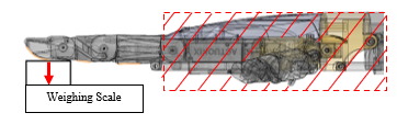
Figure 39: Setup of Force Measurement by Fixing the Palm in place.
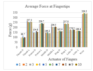
Figure 40: Flex Sensor on Little Finger.
4. Conclusion
The robot hand is designed to focus on the appearance of a human shape to represent as natural and friendly as a human form to a participant. The appearance is designed to be close to a human in shape as a prosthetic hand. Multiple types of actuators have been adopted in the transmission design to maintain performance in the limited space. The robot hand has 15 joints, 10 DOFs, and 1 wrist joint. While the linear actuator joint directly controls finger movement and utilizes Pulse Width Modulation (PWM) values for rotation measurement of MCP joint. For the PIP joint which is driven by Dynamixel by transmits power through the tendon, Flex sensors are strategically placed atop each finger, providing feedback on the angle of rotation to compensate for tendon degradation. Ensuring accuracy within plus or minus 4 degrees is achieved by applying an individual second-order polynomial curve fitting formula on each finger, derived from the calibration results. Recording the degree of rotation for each joint enables the hand to replicate hand gestures without needing physical objects. Furthermore, the hand has the capacity to hold objects and engage in communication through hand gestures. In gestures performed, 10 main hand signs can be performed. Designed within the given constraints to prioritize appearance, robotic hands can convey a wide range of gestures and symbols, including greetings, cessation signals, affection, joy, unity, resistance, agreement, distraction, contemplation, victory, and the OK hand sign. Moreover, these robotic hands can hold various daily objects, such as flat coins, stick objects like pens, cylindrical cans, or water bottles, trigger-operated spray bottles or hand sanitizers, and circular or flat cylindrical objects like sticky tape. They are even capable of engaging in handshakes for greetings, utilizing a fingertip grip for operating the computer mouse, and adopting a claw-like configuration to hold a box or document folder horizontally or to carry bag straps vertically. This hand is meticulously designed by eliminating the movement of abduction and adduction joints while maintaining a fixed angle for optimal expression of hand gestures with a suitable number of actuators in the design. Furthermore, the 3D model is accessible to any reader interested in further development at the link below.
Conflict of Interest
The authors declare no conflict of interest.
Acknowledgment
The authors would like to thank the AI for All project and the Fundamental Fund for supporting tuition fees and research equipment. Also, the authors would like to thank the Institute of Field Robotics and the King Mongkut’s University of Technology Thonburi, which is a source of knowledge and a place to develop this research.
- J. Trichada, T. Wimonrut, N. Tirasuntarakul, T. Choopojcharoen, B. Sakulkueakulsuk, “Design of an Open Source Anthropomophic Robotic Finger for Telepresence Robot,” ACM International Conference Proceeding Series, 62–66, 2021, doi:10.1145/3467691.3467704.
- M. Grebenstein, A. Albu-Schäffer, T. Bahis, et al. “The DLR hand arm system”, Proceedings – IEEE International Conference on Robotics and Automation, 3175-3182, 2021, doi: 10.1109/ICRA.2011.5980371.
- Shadow Robot, “Shadow Dexterous Hand E1 Series (E1M3R, E1M3L, E1P1R, E1P1L)”,2013.
- S. Powell, “A Review of Anthropomorphic Robotic Hand Technology and Data Glove Based Control”, M.S. Thesis, Virginia Polytechnic Institute and State University, 2016.
- I. Llop-Harillo, A. Pérez-González, J. Andrés-Esperanza, “Grasping Ability and Motion Synergies in Affordable Tendon-Driven Prosthetic Hands Controlled by Able-Bodied Subjects”, Frontiers in Neurorobotics, 14(August), 1-15, 2020, doi:10.3389/fnbot.2020.00057.
- J. Belter, J. Segil, A. Dollar, R. Weir, “Mechanical design and performance specifications of anthropomorphic prosthetic hands: A review”, Journal of Rehabilitation Research and Development, 50(5), 599-618, 2013, doi:10.1682/JRRD.2011.10.0188.
- C. Connolly, “Prosthetic hands from Touch Bionics”, Industrial Robot, 35(4), 290-293, 2008, doi:10.1108/01439910810876364.
- C. Medynski, B. Rattray, “Bebionic Prosthetic Design”, MEC 2011 Symposium MyoElectric Controls/Powered Prosthetics Symposium, 1-4, 2011.
- S. Gehrmann, J. Tang, Z. Li, R. Goitz, J. Windolf, R. Kaufmann, “Motion deficit of the thumb in CMC joint arthritis”, Journal of Hand Surgery, 35(9), 1449-1453, 2010, doi:10.1016/j.jhsa.2010.05.026.
- P.Lastayo, “Journal of Hand Therapy: Editor’s note”, Journal of and Therapy, 24(2), 79, 2011, doi:10.1016/j.jht.2011.03.002.
- W. Chen, Y. Lin, Y. Chen, K. Chen, B. Kuo, P. Tsao, Y. Lee, W. Soong, M. Jeng, “Reference equations for predicting standing height of children by using arm span or forearm length as an idex”, Journal of the Chinese Medical Association, 81(7), 649-656, 2018, doi: 10.1016/j.jcma.2017.08.023.
- I. Llop-Harillo, A. Pérez-González, J. Starke, T. Asfour, “The Anthropomorphic Hand Assessment Protocol (AHAP)”, Robotics and Autonomous Systems, 121, 2019, doi:10.1016/j.robot.2019.103259.