Control Program Generator for Vehicle Robot using Grammatical Evolution

Adv. Sci. Technol. Eng. Syst. J. 8(6), 01–07 (2023);
 DOI: 10.25046/aj080601
A robot development has spread widely for various purposes. It is difficult to create a control program for an autonomous mobile robot manually. Therefore, an automatic design of the control program for an autonomous mobile robot is proposed in this research. The autonomous mobile robot is created with LEGO MINDSTORMS EV3, and the control program for the au- tonomous mobile robot is designed using Grammatical Evolution (GE). Grammatical Evolution (GE), which is one of the evolutionary computations, is designed to generate a program or a program fragment satisfying the design objective. PyBullet is used with GE to simulate the behavior of the robot. A robot traveling along a trajectory was considered as an example. GE can generate the control program of the robot behavior of a robot vehicle traveling along a trajectory. The computer simulation reveals the robot can travel along a designated line. Since there is a reality gap between the simulator and the real environment, the parameters of the vehicle robot such as produced power and sensor sensitivity are calibrated to reduce the gap. Comparison of the computer simulation and the experimental result shows that the reproducibility of the vehicle trajectory in the real environment is high.
1. Introduction
Evolutionary algorithm (EA), which is one of the heuristic search methods, is widely applied for complex and continuous optimization problems [1]. Specially, it is very effective for solving problem with too many design variables. Evolutionary Computation includes Genetic Algorithm (GA) [2, 3], Genetic Programming(GP) [4, 5], Evolutionary Strategy (ES), Evolutionary Programming (EP) and so on.
Genetic Algorithm is widely applied for the complex optimization problem. Candidate solutions of the problem are defined as the individuals [2, 3]. Each individual has the chromosome which defines binary design variables. Population is constructed by the group of the individuals. By applying the genetic operators such as selection, crossover and mutation, individuals evolve into new individuals so that the objective function is minimized. Genetic Programming(GP) is also well-known evolutionary algorithm [4, 5]. Genetic Algorithm aims at finding the solutions of functions, whereas Genetic Programming aims at designing functions and programs [6, 7]. Individuals are defined in a binary tree structure, which is very different from them in Genetic Algorithm. Since the individuals are defined in a binary tree structure, genetic operators for GP are very different from them for GA.
Grammatical Evolution (GE), which was presented in 1998 by O’Neill and C. Ryan, is the evolutionary algorithm for determining the function or program which satisfies the design objective [8]–[10]. The aim of GE is the same as GP. Its algorithm, however, is slightly different. Individuals of GE are defined in the binary or string, like GA. The translation from the binary or integer numbers to function or program is performed according to Backus-Naur form (BNF), which is defined by a user in advance. Authors’ colleagues applied Grammatical Evolution to symbolic regression problem, stock price prediction problem and generation of control program of artificial ant in computer simulation [11]–[14]. In this study, Grammatical Evolution is applied for generating the control program of a real vehicle robot. A vehicle robot is made of LEGO MINDSORM EV3 [15, 16].
PyBullet is utilized for simulation of the actual robot motions [17, 18] . This environment is widely utilized as a robot learning environment for manipulation due to its portability and light weight for variety of machine learning tasks [19]. After the program is created in the simulation environment, it is applied to control the actual robot. Since there are differences in sensor sensitivity and motor output between the actual robot and the robot in the simulation environment, the program is modified to compensate for the differences. The results of the robots in the actual and the simulation environments are compared for discussing the validity of the generated program.
The remaining part of this paper is organized as follows. The evolutionary computations are introduced in Section 2. In Section 3, experiments and discussion of control program design using GE are performed. In Section 4, the designed control program is applied to the actual vehicle robot. The conclusion and future issues are summarized in Section 5.
2. Grammatical Evolution
2.1 Outline
Grammatical Evolution is designed to find a function or a program satisfying the design objective. GE composes the initial population by the individuals with randomly generated bit-strings or the sequence of integer numbers [20]. The translation from the integerstring to the program is performed according to the translation rules of Backus-Naur Form (BNF) grammar [21]. After the integer-string of each individual is translated into a function or a program, its fitness is evaluated. The individuals are updated by using genetic operators such as selection, crossover, and mutation with the individual fitness. These process are repeated till the design objective is satisfied. The process is summarized as follows.
- Define translation rules based on targeted task, which translates integer string to a function or a program.
- Generate individuals from integer string randomly to define an initial population.
- Translate the integer-string of each individual into a program.
- Select parent individuals from population according to fitness.
- Apply genetic operators such as selection, crossover, and mutation to parent individuals to generate offspring individuals.
- Update population.
- If the individual satisfying the design objective can be found, the results are output. If not so, go back to Step 3.
2.2 Translation from Integer String to Program
The translation rules are defined with the set of non-terminal symbols N , the set of terminal symbols T , and the start symbol S. Non-terminal symbols are replaced with the other non-terminal or terminal symbols according to the translation rules. Terminal symbols, on the other hand, is no longer replaced. The sets of the symbols are summarize as follows.
N = { <code>,<op>,<var> }
T = { +,-<*,/,X }
S = { <code> }
The translation rule is shown in Table 1. The symbol ”|” means “or”. The symbol <code> (A) is replaced with one of three candidates; <code><code> (A0), <op> (A1), and <var> (A2). The symbol <op> and <var> have four candidates and one candidate,
respectively.
Table 1: Example of Simple Translation Rules
| (A) | <code> | ::= | <code><code> | (A0) |
| | | <op> | (A1) | ||
| | | <var> | (A2) | ||
| (B) | <op> | ::= | + | (B0) |
| | | – | (B1) | ||
| | | * | (B2) | ||
| | | / | (B3) | ||
| (C) | <var> | ::= | x | (C0) |
Table 2: Evolution of Symbols
| Sn | rA | m | A | Selected symbols | Replaced symbol |
| <code> | |||||
| 3 | 3 | 0 | <code> | <code><code> | <code><code> |
| 0 | 3 | 0 | <code> | <code><code> | <code><code><code> |
| 2 | 3 | 2 | <code> | <var> | <var><code><code> |
| <var> | x | x<code><code> | |||
| 1 | 3 | 1 | <code> | <op> | x<op><code> |
| 2 | 4 | 2 | <op> | * | x*<code> |
| 2 | 3 | 2 | <code> | <var> | x*<var> |
| <var> | x | x*x |
The translation process is summarized as follows. For example, assuming that the individual is defined as “302122”, the translation of “302122” according to Table 1 is shown in Table 2. The start symbol is α = <code>. The leftmost not-used gene is n0 = 3. The symbol α = <code> has three potential symbols, n0 = 3. Since the remainder of n0 = 3 divided by nα = 3 is nr = 0, the symbol α = <code> is replaced with 0-th symbol of the candidates <code><code>.
Next, the leftmost symbol α = <code> of the symbols <code><code> is replaced as follows. The second leftmost not used number of the individual is n0 = 0. The symbol α = <code> has three candidates and thus, n0 = 3. Since the remainder of n0 = 0 divided by nα = 3 is nr = 0, the symbol α = <code> is replaced with the symbol <code><code> and then, the symbols <code><code> becomes the symbols <code><code><code>.
Next, the leftmost symbol α = <code> of the symbols <code><code><code> is replaced as follows. The third leftmost not-used number of the individual is n0 = 2. The symbol α =<code> has three candidates and thus, nα = 3. Since the remainder of n0 = 2 divided by nα = 3 is nr = 2, the symbol α = <code> is replaced with the symbol <var> and then, the symbols <code><code><code> becomes the symbols <var><code><code>. According to the similar process, the individual “302122” results in x ∗ x. The whole process is shown in Table 2.
3. Design of Control Program
3.1 Robot Vehicle
The robot vehicle is created by LEGO MINDSTORMS EV3 (Fig.1). LEGO MINDSTORMS is an educational robot kit jointly developed by LEGO and Massachusetts Institute of Technology. LEGO MINDSTORMS EV3, which was released in 2013, contains an intelligent block with a 32bit ARM9 microprocessor which allows the robot to operate autonomously by downloading and executing the program. Several sensor such as an ultrasonic sensor, a color sensor, a gyro sensor, and a touch sensor can be attached to the input port and then, the values of each sensor can be used to control the servo motor connected to the output port.
For rapid software development, the robot is loaded with MicroPython firmware for complete integration with a Python-based simulation environment. For uploading and debugging programs on robots, a standard IDE such as Visual Studio Code is utilized. Actual course used in this experiment is shown in Fig.2.
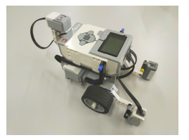
Figure 1: Lego Mindstorms EV3
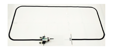
Figure 2: Actual Course
3.2 Simulation Environment
PyBullet is utilized for simulation due to its capability to replicate actual robot motions using Bullet Physics Engine and stability in repetitive machine learning calculations [17] . This environment is widely utilized as a robot learning environment for manipulation due to its portability and light weight for variety of machine learning tasks.
Robot and track model is generated using standard Unified Robot Description Format (URDF) used in Robotics Operating System (ROS) [22]. Object physic characteristics can be defined deliberately in the XML-styled format thus comparatively fasten simulation environment with accurate parameters. Center of axle is configured as measurement point for positional analysis.
Detailed dimensions of the course is shown in Figure 3. The course design is performed by placing 30cm x 30cm tiles on a 240cm x 120cm field. Lines center is located at the center of the tiles with thickness 25mm to match attachment height of the reflection sensor. This setup will enable the reflection sensor to completely sense whether the surface reflect light or not. Tiles with various shapes are prepared, and it is possible to design a course according to the purpose. START, GOAL, and CHECKPOINT can be set for tiles as their specifications. The START tile is the starting position of the robot, which determines where and in what direction to place the robot first. The GOAL tile is the end of the robot motion. When the center of the robot’s axle enters the GOAL tile, the simulation is terminated. The CHECKPOINT tile is functioned as Checkpoint for the robot motion. In Fig. 4, the tiles numbered with i = 1, ·
- · , 18 denote the CHECKPOINT tiles. A robot has to pass all CHECKPOINT tiles when a robot moves along a line.

Figure 3: Dimension of Course
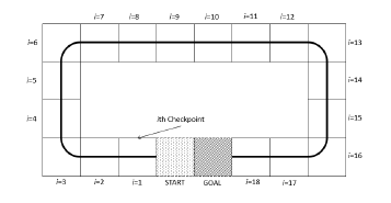
Figure 4: Course Checkpoint
3.2.1 Control Program Translation rules
Grammatical Evolution can generate the best control program from the randomly defined candidate programs according to translation rules known as Backus-Naur Form (BNF) Grammar.
Table 3 shows the translation rule defined for this experiment.
In defining the translation rule, the control statements of LEGO MINDSTORMS EV3 are introduced. This statements consists control statement used in PyBullet and LEGO MINDSTORM EV3, and can be controlled with identical control statement both in simulator and real machine.
The translation rules are defined with the set of non-terminal symbols N, the set of terminal symbols T, and the start symbol S.
The sets of the symbols are summarize as follows.
N = { <code>,<op>,<num> }
T = { if( SensorValue > (100+ )/2 ): else:, motor( , , ),-100,-90,-80,-70,-60, -70,-60,-50,-40,-30,-20,-10,0,10,20,
30,40,50,60,70,80,90,100 } S = { <code> }
The symbol <code> (A) can be replaced with one of three candidates; <code><code> (A0), <op> (A1) and if( SensorValue > (100+<num>)/2 ): <op> else: <op>(A2). The symbol <op> and <num> have one candidate and 21 candidates, respectively.
Table 3: Translation rules
| (A) | <code>::= | <code><code> | (A0) |
| | | <op> | (A1) | |
| | | if SensorValue>(100+<num>)/2{<op>} else{<op>} | (A2) | |
| (B) | <op>::= | motor(<num>,<num>,100+<num>) | (B0) |
| (C) | <num>::= | -100 | (C0) |
| | | -90 | (C1) | |
| | | -80 | (C2) | |
| | | -70 | (C3) | |
| | | -60 | (C4) | |
| | | -50 | (C5) | |
| | | -40 | (C6) | |
| | | -30 | (C7) | |
| | | -20 | (C8) | |
| | | -10 | (C9) | |
| | | 0 | (C10) | |
| | | 10 | (C11) | |
| | | 20 | (C12) | |
| | | 30 | (C13) | |
| | | 40 | (C14) | |
| | | 50 | (C15) | |
| | | 60 | (C16) | |
| | | 70 | (C17) | |
| | | 80 | (C18) | |
| | | 90 | (C19) | |
| | | 100 | (C20) |
At translation rule (A), the statement <code><code> in Rule
(A0) adds the evolvable mechanism. Direct selection of motor control is added using the statement <op> in Rule (A1) that enable the selection of motor movement directly. For sensor input, if SensorValue>(100+<num>)/2{<op>}else{<op>} is used as if-statement to control the motor movements upon receiving the sensor value. The statement SensorValue get the output from color sensor which is integer between 0 to 100 and the conditional value (100+<num>)/2 is used to match the color sensor input in increments of 5. This conditional statement produces two executable statements <op>, first statement is executed when the sensor value is larger than selected value, otherwise the second statement is executed. This allows the color output of the sensor change the pattern of the motor input.
At translation rules in (B), the statement motor(<num>,<num>, 100+<num>) is the control statement for the motors, where the arguments are for left motor, right motor and waiting time for the movement to complete. The statement <num> for first and second argument is used to select the speed input range from -100 to 100 in 10 increments. Negative value means the motor will run backwards with percentage ratio. The statement 100+<num> is a control argument that sets the execution time (ms) of motor power input. Since the argument started with value of 100, only positive value will be produced from 0 to 200 in increments of 10.
At translation rule C, a common usable parameter with a value between -100 and 100 is set so that it can be used for sensor and motor input conditional values.
3.2.2 Fitness Function and Parameters
Each generated program is evaluated using a fitness function capable of achieving the goal by passing all checkpoints in less than 60 seconds. The fitness function is defined such that lower values indicate a better solution, so that the control program generation problem is appointed as a minimization problem. The objective function is defined as below.
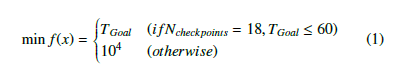
where Ncheckpoints and TGoal represent number of checkpoints
tiles,i-th and total time taken,T (s) to reach the GOAL tile, respectively. Only individuals that pass through within all 18 checkpoints are evaluated and beyond that the fitness is penalized with very large number(104). Large number is used as fitness scaling to control diversity to prevent the populations converge to early toward a single optimal solution[3]. Solutions fitness that go beyond the tiles will also be deducted until the trajectories of robot follow the line and finally reach the determined target. Parameters used is shown in Table 4
Table 4: GE Parameters
| Population size | 200 |
| Maximum generation | 50 |
| Gene length | 1000 |
| Number of elites | 1 |
| Selection | Tournament |
| Tournament size | 5 |
| Crossover type | One-point crossover |
| Crossover rate | 0.4, 0.5, 0.7 |
| Mutation rate | 0.03, 0.05, 0.07 |
3.3 Simulation Results
In Figure 5 , we perform five simulations with different initial values and show the average value. This attempts to remove the influence of how the initial values were selected. The horizontal and the vertical axes represent the number of generations and the arrival time to the GOAL tile, respectively. The result of the crossover rate 0.5
and the mutation rate 0.05 demonstrates the quickest convergence during the initial generation. Table 5 shows the average fitness of the best individual in the final generation for different crossover rates and mutation rates. When the crossover rate is 0.4, the simulation did not converge for mutation rate 0.03 and 0.05, but shows lowest rate of convergence when mutaton rate is 0.07. The best fitness is obtained when the crossover rate is 0.5 and the mutation rate is 0.05.
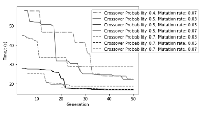
Figure 5: Convergence history travel time over generation
Table 5: Effect of Crossover and Mutation rate
| 0.03 | 0.05 | 0.07 | |
| 0.4 | – | – | 22.51 |
| 0.5 | 22.32 | 16.74 | 17.20 |
| 0.7 | 28.64 | 16.98 | 18.74 |
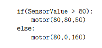
Figure 6: Generated program
Fig.6 shows the program generated based on the best individual of the final generation. It is notice that the best generated program is a simple line tracing program. When the color sensor of a robot vehicle notices white on the course, the vehicle moves forward with the maximum motor output. When the color sensor notices black, the vehicle rotates to the right on the spot. At the start, the vehicle moves forward because the color sensor is positioned on the white field. When the color sensor enters the black line, the vehicle rotates to the right. After completing the rotation, the vehicle moves forward because the color sensor is positioned on the white field. After repeating forward and right turns alternately four times in this way, a robot vehicle goes straight and reach the GOAL tile.
4. Experiment
4.1 Performance Estimation of Robot Vehicle
LEGO MINDSTORMS EV3 robot can be controlled using motor power input (Duty Cycle) in percentage and speed input. When the motor is assigned with increments of speed in 2s interval time, rotational speed increases and reached the limit of 800degree/s as shown in the Fig. 7 which is equivalent to the maximum of 80% of the power input. Motor power input is capped to 80% and the limitations are also applied to the simulation.
Motor power input is a simple method to control the movement of the robot by supplying current to the motor in ratio. The estimation of motor speed require actual power input when the robot is under actual load when moving around the track with surface friction. Fig.8 shows the relation between power and rotational speed of motor in degree/s.
4.2 Kinematics of Robot
Grammatical Evolution program uses speed input to vary the velocities of the two wheels, thus determine the trajectories of the robot. Actual robot used in this experiment utilize Differential-drive Robot concept where two independent motor with wheel radius,r rotate about the same axis and low-friction caster wheel is used to keep the robot horizontal.
For left and right motor linear velocity, vl and vr, where R is distance from center of curvature to the center of the axle and l is effective distance between wheel (axle), kinematics equation based on Instantaneous center of curvature concept for the system is shown below;
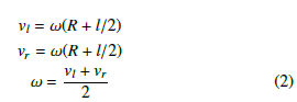
By varying the motor speed for left and right, trajectories of the robot can be determined based on the turning rate, ω.
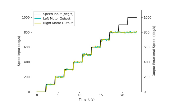
Figure 7: Relation between Speed input and Rotation Speed (degree/s)
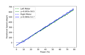
Figure 8: Relation between Power and Rotation Speed (degree/s)
4.3 Actual Robot Experiments
Evaluation of the simulation is done by using the actual robot with identical dimensions to prove the effectiveness of the program generated. Program generated from GE is executed to check the effectiveness.
Figure 9 shows the trajectory of the vehicle. A robot vehicle starts from the position of X=0 and Y=0 and then, makes one lap around the course clockwise. A solid line shows the computer simulation result and broken lines denote actual experiment results of five trials of vehicle robot, respectively. Table 6 shows the arrival time for 5 trials performed. Maximum, minimum, and mean arrival times are 18.71 (s), 19.92 (s) and 19.30 (s), respectively. Since the arrival time of the simulation is 16.74 (s), the errors of maximum, minimum, and mean arrival times are 11.8 (%), 19.0 (%) and 15.4 (%), respectively. In experiments using actual robots, it is expected that the arrival time becomes longer than that in simulations due to factors such as robot acceleration and control delay time.
This difference in time elapsed is caused by the actual robot movement take a longer path to make turn for each line corner. Longer sensor responses and efficiency of the motor are two main reasons which create a tiny small lag for the robot to make turns. Even there is a small time difference, the robot control program able to accomplish the main objective which is following the line. In addition, Figure 10 shows the difference between the vehicle position in the simulator and in the real environment at each time step (0.01s). The error fluctuates up and down with time, but basically increases with time.
The correlation coefficient between the vehicle coordinates in the simulator and the experiment is evaluated for the trajectory of the vehicle, and the result is show in Table 7. A high correlation is shown in both the x-coordinates and y-coordinates. It can be seen that the correlation coefficient for the y-coordinate is lower than that for the x-coordinate. From Fig. 9, it is expected that the deviation of the y-coordinate between the simulation and the experiment is relatively large.
Table 6: Running Time
| Experiment | Arrival time (s) | Error (%) |
| Trial 1 | 18.98 | 13.4 |
| Trial 2 | 19.51 | 16.5 |
| Trial 3 | 18.71 | 11.8 |
| Trial 4 | 19.92 | 19.0 |
| Trial 5 | 19.47 | 16.3 |
| Average | 19.32 | 15.4 |
Arrival time at simulation : 16.74 (s)
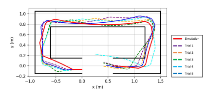
Figure 9: Robot path comparison between simulation and actual
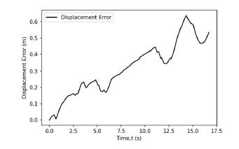
Figure 10: Displacement between vehicle position in simulator and real world
Table 7: Correlation coefficient between vehicle coordinates in simulation and experiment
| x-coordinate | 0.9553 |
| y-coordinate | 0.7743 |
5. Conclusion
A method of designing a control program for an autonomous mobile robot using Grammatical Evolution (GE) was proposed in this research. The autonomous mobile robot was created with LEGO MINDSTORMS EV3, and the control program for the autonomous mobile robot was designed using Grammatical Evolution (GE). Robot Virtual Worlds was used to simulate the behavior of the robot.
A robot traveling along a trajectory was considered as an example. As a result, the fitness converged toward the optimal solution, and the running trajectory of the robot according to the designed control program was appropriate. A real machine experiment was performed by applying the control parameters that adjust the gap between the simulator and the real environment. Comparing the computer simulations and experimental results shows that the target achievement time in the running experiment was equivalent to that of the simulator. In addition, it was shown that the reproducibility of the vehicle trajectory in the real environment was high. Finally, future issues is summarized as follows. First, to reduce the computational time, an algorithm should be revised to improve the convergence performance. Secondly, the experiments with complicated courses and conditions should be performed to verify the effectiveness of the proposed method for many problems.
- H.-P. P. Schwefel, Evolution and Optimum Seeking: The Sixth Generation, John Wiley & Sons, Inc., USA, 1993.
- J. H. Holland, “Adaptation in natural and artificial systems,” University of Michigan press, Ann Arbor, MI, 1, 1975.
- D. E. Goldberg, “Genetic Algorithms in Search, Optimization, and Machine Learning,” NN Schraudolph and J., 1, 1989.
- J. R. Koza, Genetic Programming II: Automatic Discovery of Reusable Pro- grams, volume 1, MIT Press, 1994.
- J. R. Koza, Genetic Programming lll: Darwinian Invention and Problem Solv- ing, Morgan Kaufmann, 1999.
- V. de Carvalho Santos, C. F. M. Toledo, F. S. Osorio, “An exploratory path planning method based on genetic algorithm for autonomous mobile robots,” 62–69, IEEE, 2015, doi:10.1109/CEC.2015.7256875.
- R. Kala, “Multi-robot path planning using co-evolutionary genetic pro- gramming,” Expert Systems with Applications, 39, 3817–3831, 2012, doi: 10.1016/j.eswa.2011.09.090.
- C. Ryan, J. Collins, M. O. Neill, Grammatical evolution: Evolving programs for an arbitrary language, volume 1391, 83–96, 1998, doi:10.1007/BFb0055930.
- M. ONeil, C. Ryan, “Grammatical evolution: Evolutionary automatic program- ming in an arbitrary language,” Norwell, MA, 10, 1–978, 2003.
- C. Ryan, M. ONeill, J. J. Collins, Introduction to 20 years of grammatical evolution, 2018, doi:10.1007/978-3-319-78717-6 1.
- T. Kuroda, H. Iwasawa, E. Kita, “Application of advanced Grammatical Evolution to function prediction problem,” Advances in Engineer
- E. Kita, Y. Zuo, H. Sugiura, T. Mizuno, “Acceleration of Grammatical Evo- lution with Multiple Chromosome by Using Stochastic Schemata Exploiter,” Proceedings – 2017 4th International Conference on Mathematics and Com- puters in Sciences and in Industry, MCSI 2017, 2018-Jan, 190–195, 2018, doi:10.1109/MCSI.2017.40.
- H. Sugiura, M. Nagao, Y. Zuo, E. Kita, “Grammatical evolution using two- dimensional gene for symbolic regression: An advanced improvement with conditional statement grammar,” International Journal of Critical Infrastruc- tures, 13, 2017, doi:10.1504/IJCIS.2017.083634.
- E. Kita, H. Sugiura, Y. Zuo, T. Mizuno, “Application of grammatical evolution to stock price prediction,” Computer Assisted Methods in Engineering and Science, 24, 2017.
- L. Group, “LEGO MINDSTORMS EV3,” 2023.
- L. G. 2019-2020, “LEGO MINDSTORMS Education EV3 MicroPython,” 2020.
- E. Coumans, Y. Bai, “PyBullet, a Python module for physics simulation for games, robotics and machine learning,” 2017.
- F. Sukarman, E. Kita, “Auto-generated Control Program in Mobile Robot using Grammatical Evolution,” 1–5, Association for Computing Machinery, 2022, doi:10.1145/3573910.3573921.
- X. Yang, Z. Ji, J. Wu, Y.-K. Lai, “An Open-Source Multi-goal Reinforcement Learning Environment for Robotic Manipulation with Pybullet,” Lecture Notes in Computer Science (including subseries Lecture Notes in Artificial Intel- ligence and Lecture Notes in Bioinformatics), 13054 LNAI, 14–24, 2021, doi:10.1007/978-3-030-89177-0 2.
- M. Fenton, J. McDermott, D. Fagan, S. Forstenlechner, E. Hemberg, M. O’Neill, “PonyGE2: Grammatical evolution in python,” GECCO 2017- Proceedings of the Genetic and Evolutionary Computation Conference Com- panion, 1194–1201, 2017, doi:10.1145/3067695.3082469.
- G. Dick, P. A. Whigham, “Initialisation and grammar design in grammar-guided evolutionary computation,” 534–537, ACM, 2022, doi:10.1145/3520304. 3529051.
- O. R. 2021, “ROS – Robot Operating System,” 2021.