Design and Prototyping of a 3DOF Worm-drive Robot Arm

Adv. Sci. Technol. Eng. Syst. J. 8(5), 77–93 (2023);
 DOI: 10.25046/aj080509
Many designs for robot arms exist. Here we present an affordable revolute arm, capable of executing simple pick-and-place tasks. The arm employs a double parallelogram structure, which ensures its endpoint angle in the plane of the upper arm remains fixed without the need for additional actuation. Its limbs are fabricated from circular tubes made from bonded carbon fiber, to ensure low moving mass while maintaining high rigidity. All custom structural elements of the arm are produced via 3D printing. We employ worm-drive DC motor actuation to ensure that stationary configurations are maintained without the necessity of continuous motor power. Our discussion encompasses an analysis of the arm’s kinematics. A simulation of the arm’s operation was carried out in MATLAB, revealing key operational metrics. In conclusion, we achieved extrinsic endpoint position tracking by implementing its inverse kinematics and PID control using a microcontroller. We also demonstrate the arm’s functionality through simple movement tracking and object manipulation tasks.
1. Introduction
1.1. Extension of previous work
This paper builds upon work on a prototype 2D planar arm first published in the proceedings of the 2022 International Conference on System Science and Engineering (ICSSE) [1]. We explicitly highlight the extensions of previous work and novel contributions of this study at the beginning of the discussion section.
1.2. Overview
Brought about by a combination of a dwindling agricultural workforce and advancements in robotics technology, the deployment of robots for harvesting fruits and vegetables has become an increasingly important area of development [2]. As a result, there is a growing demand for low-cost robots to not only reduce the cost of harvesting but also to address the shortages in agricultural workers willing to perform the task.
As a typical application area, we consider the development of robotic arms designed to harvest berries from plants. For such an application, robotic arms are normally attached to a computer-controlled mobile robot base. These systems typically operate in structured environments, such as greenhouses, and must autonomously identify, pick, and collect ripe berries. The design of suitable robotic arms involves trade-offs, as multiple requirements need to be met [3].
1.3. Requirements
To offer a realistic alternative to employing human workers, any useful arm design needs to perform its picking tasks effectively with no greater, and preferably lower, overall operating costs. Therefore, keeping the cost of arm construction low is an important design consideration.
In terms of performance, the workspace of the arm must be sufficient for it to reach the berries chosen for picking, and it must be able to do so with reasonable accuracy (of the order of millimeters). Ideally, it should accomplish this with minimal correction during movement, avoiding the need for visual servoing [4]. The arm must also generate sufficient force to hold and operate a suitable end effector mechanism to pick the berries. Pulling off a raspberry can require up to 10N [5], although alternative removal techniques, such as cutting, are also viable [6]. Force generation requirements place demands on the joint torques needed, as well as on the stiffness and strength of the arm structure. Clearly, a balance must be struck between arm link length and stiffness, given that arm stiffness decreases rapidly as a function of link length.
The actuation and control mechanisms of the arm should prioritize power efficiency, as mobile picking systems generally operate from batteries. To address limitations in the use of batteries, researchers are exploring the possibilities of harnessing solar energy to recharge the batteries when daylight conditions permit [7].
The arm must ensure safe operation in the proximity of people and guidelines for safe robot operations are specified by the ISO 10218 standard [8]. To do so, it must effectively manage occasional, inevitable collisions with items in its environment, which could include greenhouse plant support infrastructure or even curious human workers standing too close to the robot. Paramount attention must be paid to this issue, to prevent any injury or damage resulting from inadvertent collisions.
Several strategies can facilitate safe robotic arm operation. One approach involves building inherent compliance into their designs [9,10]. One such design, the Gummiarm, achieves this by making use of compliant non-linear tendons driven by Dynamixels [11,12]. However, incorporating passive compliance can often compromise performance.
Another way to enhance robot safety is to limit the arm’s kinetic energy due to movement. This can be achieved by restricting the maximum operational speed and ensuring the arm has a lightweight structure, thereby reducing potential damage arising from a collision.
1.4. Collaborative robots
Much work has been carried out to make industrial robots safe around people [13–15]. A collaborative robot, (also known as a cobot), is a specialized robot, engineered to work in tandem with humans within a shared workspace.
Cobots are often equipped with an array of sensors, including cameras, force sensors, and proximity sensors, which enable them to sense and interact with their surroundings. These sensors allow cobots to identify human presence, avert collisions, and react to environmental changes. Furthermore, cobots incorporate safety features, such as force-limiting and speed-limiting controls, which contribute to accident prevention and the protection of human co-workers. A popular safety strategy employed in cobots, is to monitor their force generation [16]. If force levels exceed expected task values, the robot identifies this anomaly as a probable fault condition and safely deactivates the robot in a controlled manner.
Numerous companies, researchers, and engineers have embraced the cobot concept. Universal Robots, a Danish company, was among the first to introduce a cobot, and Rethink Robotics was also an early pioneer in the cobot domain. Cobots are gaining traction across a broad spectrum of industries, including manufacturing, logistics, and healthcare.
1.5. Lightweight arms
Several lightweight arms are commercially available. The Barrett WAM, popular among researchers, features low weight and employs a cable drive. Its actuation exhibits very low backlash and low friction, while the arm itself demonstrates a low effective mass [17].
The ANYpulator is another example of a lightweight robotic arm. It employs force control and utilizes lightweight carbon fiber links in its construction to minimize moving mass [18].
The DLR lightweight robot provides another example of high-quality arms capable of safe operation [15]. Kuka has commercialized its design, which also serves as the basis for the Franka Emika arm [19].
1.6. Existing low-cost robots
Most of the commercially available robots mentioned earlier are quite expensive. However, several low-cost robotic arm designs also exist. For instance, Reachy employs off-the-shelf components and fully 3D-printed limb sections [20].
The BioRob-Arm [21] is a lightweight design that utilizes compliant actuation. It is based on an antagonistic, series-elastic actuation that employs cable transmission [22].
Another compliant, 7-DOF (Degrees of Freedom) robotic arm was developed at Stanford University. To keep costs down, the design makes use of stepper motor drive and adopts series-elastic transmission in the lower arm and base. It adopts Dynamixels for actuation in the remaining three [23].
More recently, the Berkeley Blue 7-degree-of-freedom arm has been developed with the intention of making a low-cost, force-controlled robot available to the wider AI community [24].
2. Arm design
2.1. Design and construction overview
In this section, we focus on designing a lightweight arm driven by worm-gear motors, via HTD 5M x 15mm wide timing belts, enabling it to maintain static configurations without requiring constant motor power. The arm design is based on a revolute configuration. See Figure 1 for a photograph of the arm, Figure 2 for a close-up of the pulley actuation, and Figure 3 for labelled schematics indicating important parts of the robot design.
The design of the arm was carried out using Autodesk Fusion 360. To ensure minimal weight, the upper and lower parallelogram arm sections employed carbon fiber tubing, with dimensions of 16x14mm in diameter and 250mm in length.
All parts that were custom-designed were initially exported in the STL file format, subsequently sliced employing Ultimaker Cura software, and 3D printed utilizing PLA+ material with a Creality CR-6 SE printer. To optimize stiffness and strength, arm joint components were printed with a 100% infill [25]. Additional components were printed with a 35% infill to strategically minimize their moving mass. Keeping the weight of the components low was particularly important for the upper arm mechanism support pillars, as they rotate during the operation of the arm.
Loctite Precision superglue was used to attach the carbon fiber tubes to their corresponding 3D printed PLA+ parts.
2.2. Rotary base
The first arm joint is achieved using a platform that rotates around a vertical axis. This platform supports a planar arm mechanism, which provides an additional two degrees of freedom.
The top of the rotary base assembly is fabricated from plate sections. These are both 20mm-thick and are 3D-printed. They are supported by two side pillars resting on a single, similarly thick 3D-printed base plate. These components are secured together using four long bolts. The top two base plates tightly secure a deep groove ball bearing in place. It has a large internal bore of 50mm to accommodate a 3D-printed shaft, which passes through the bearing. The shaft is affixed to the bearing assembly, using a 3D-printed clamping collar. This provides the shaft with radial and axial support. The collar incorporates an integrated 40-tooth HTD 5M x 15mm timing pulley. The shaft represents the arm’s first degree of freedom. The upper end of the main shaft features a flat plate with mounting holes, so the upper arm assembly can be bolted onto it.
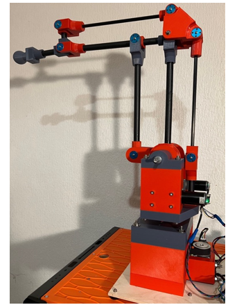
Figure 1: 3 DOF worm-gear motor robotic arm. The base mechanism serves as the initial rotational joint of the arm. Incorporating two degrees of freedom (2DOF), the upper segment adopts a parallelogram design.
The main shaft timing pulley on the collar is driven by a timing belt. A worm-gear motor, fitted with a smaller aluminum 24-tooth HTD 5M x 15mm timing pulley, drives the other end of the timing belt in order to rotate the shaft (Figure 2B). The motor itself is located on the lower base plate.
2.3. Two-degrees of freedom parallelogram design
The upper part of the arm mechanism is mounted on the main axis and is rotated by the base assembly, as depicted in Figure 3. Its design incorporates a mechanism to maintain the orientation of the endpoint in the plane of the upper arm, eliminating the need to control this linkage explicitly.
The main upper arm link L2 is supported and driven by a 3D-printed component that incorporates a 40-tooth HTD 5M x 15mm wide timing pulley. The component incorporates 2 x 8mm ball bearing races and is located on the main 8mm-diameter parallelogram mechanism shaft.
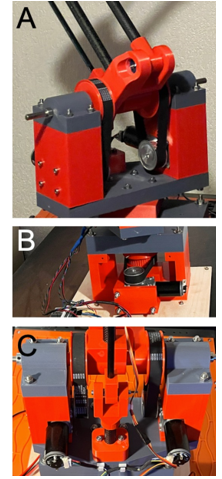
Figure 2. Close-up view of the rotating base platform mechanism. Panel A: Front view of the pulleys drive connected to the parallelogram arm mechanism. Panel B: The horizontal pulley drive for J1 for the first rotary axis of rotation. Panel C: Rear view of the parallelogram pulley drive showing worm-gear motors.
The secondary upper arm link arm is supported and driven by a 3D-printed mini-arm component, which also incorporates a 40-tooth HTD 5M x 15mm wide timing pulley. This component also incorporates 2 x 8mm ball bearing races and is likewise located on the main 8mm-diameter parallelogram mechanism shaft.
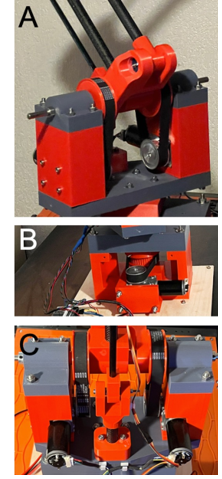
Figure 3: Robot viewed from the side. Panel A: Depicts the main components of the base and upper parallel arm links. Panel B: Shows the passive arm components and drive belts for the main arm. Panel C: Highlights the locations of the bearings, motors, and encoders.
The lower link L3 is driven by the main arm link L2 and secondary link L2 via custom made 3D-printed joint components (see Figure 3A).
To maintain the consistent orientation of the final arm link (wrist link L4), and consequently the endpoint, within the plane of the parallel arm mechanism, a passive orientation system is strategically situated behind the main arm. This ensures stable positioning and alignment throughout the operational movements of the arm mechanism. This additional parallelogram structure makes use of solid 8mm diameter carbon fiber rods in its construction. Figure 4A illustrates the endpoint alignment rocker mechanism, and the endpoint alignment mechanism and end-effector attachment point are shown in Figure 4B. This configuration enables the planar arm mechanism to preserve the endpoint orientation angle within the plane of the parallel arm without necessitating additional explicit actuation. As a result, the upper arm demands only two actuators for control, instead of three.
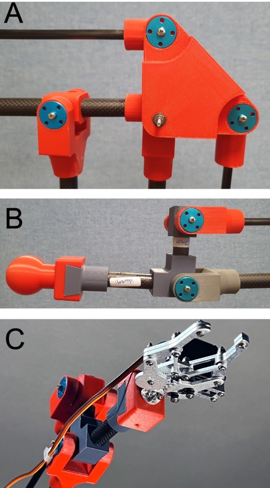
Figure 4: Panel A: The 2D upper arm features an endpoint alignment joint component located at the elbow. Panel B: The endpoint orientation mechanism. A dovetailed profile at the lower end of the last limb segment provides a connection point for end effectors. Here, a round knob is attached for safe demonstration purposes. Panel C: Simple commercially available RC-servo gripper mechanism attached to arm to demonstrate pick-and-place operations.
2.4. Arm joint components
The arm design relies on the use of joints, which utilize miniature ball-races to minimize friction. Figure 5 shows arm joint components and their assembly is depicted in Figure 6. Each fork utilizes two lightweight aluminum flanges to support a shaft passing through the bearings, making use of the enhanced mechanical properties of aluminum compared to plastic. A long M3 screw is used as the joint shaft and is held in its support fork by means of a nylon insert hex locknut. Washers are strategically positioned on the screw shaft to achieve joint clearance between the joint bearing and the aluminum flanges.
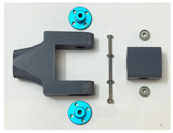
Figure 5: Components of the arm joints. The bearing component on the right-hand side hold miniature ball bearing races with a 3mm internal diameter. An M3 bolt is used as the joint shaft. When assembled, the joint bearing component locates between the two-sided support, illustrated on the left. This employs aluminum guides to hold the shaft. Washers are used to obtain suitable joint clearance.
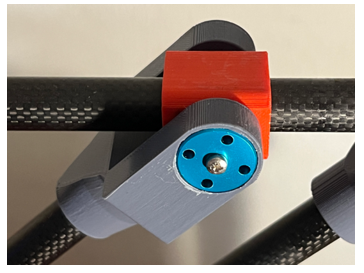
Figure 6: 2D Arm joint mechanism. Fundamental to the arm mechanism design, the arm joints utilize small ball bearings to ensure high precision and low friction operation.
2.5. Actuation using worm-drive motors
We utilize worm-gear motors for the arm’s actuation. Opting for brushed worm-drive DC motors proves advantageous in constructing a robust servo drive system due to their wide availability, cost-effectiveness, and capacity to deliver high torque. Furthermore, the inherent non-back drivable characteristic of these drives guarantees the maintenance of a static joint configuration without necessitating continuous motor power [26].
The selected worm-gear motors run from a 24V supply, drawing up to 1A under full load. The worm gearing achieves a rotary speed reduction of 280, and the motor units achieve an unloaded output shaft speed of 28 RPM and an operational torque of 5Nm. These motors are equipped with Hall sensor encoders, located at the back, which deliver 11 pulses per revolution. This configuration allows the motor output shaft angle to be estimated with high accuracy and an output angular resolution of 3080 pulses per revolution was achieved. This figure can also be quadrupled further by utilizing the pulse edges.
As previously described, the motor output shafts are connected to the arm joints’ drive axes utilizing 24-tooth HTD 5M x 15mm timing pulleys. The maximum angular speed of each driven joint, when using the selected worm-gear motors, is dictated by both the maximum motor rotational speed, converted from RPM to radians per second, and the mechanical advantage offered by the pulley drive. Consequently, given that all robot axis joints employ identical pulley ratios, the following value is obtained:
![]()
The maximum joint torque that can be achieved is given by the maximum continuous torque motor scaled up by the mechanical advantage of the pulley drive:
![]()
The robot arm incorporates three worm-drive motors in total. The main vertical revolute joint axis assembly, which integrates a 3D-printed timing pulley, is actuated by the first worm-gear-driven timing belt assembly. Moreover, two additional worm-drive motors mount within the pillars of the rotating vertical axis platform. The second joint motor engages a pulley to drive the main upper arm parallelogram arm link, while the third engages a timing pulley within the secondary arm drive link. Figure 2 illustrates the worm-drive motors, pulleys, and timing belts on the physical robot.
3. Gripper end effector for the arm
3.1. Gripper designs
Grippers are crucial end-effectors for robotic arms, enabling them to execute a myriad of tasks. Numerous designs have been proposed [27,28]. They are also an integral component of robotic harvesting technologies [29,30]. In addition to gripper designs that utilize hard materials, there is a significant contemporary interest in using soft materials for gripper construction [31,32].
3.2. RC servo operated gripper
Although pneumatic operation can offer a high-power density and a clean method of actuation for grippers, we chose to use RC servo actuation for easier integration into the current system. To demonstrate straightforward pick-and-place procedures with the arm, we affixed a low-cost, commercially available aluminum alloy RC-servo gripper mechanism to the arm via its dovetail connection point (refer to Figure 4C). This lightweight gripper assembly, weighing 160g, is capable of supporting simple pick-and-place tasks under direct human operator control.
We also designed and built a prototype RC servo-driven gripper with soft Ninja Flex cups at the ends of its fingers, specifically for assisting in gripping berries (refer to Figure 7). This gripper is lightweight, weighing 202g, and is attached to the arm through its dovetail connection point. We utilized this gripper to showcase the robotic arm’s ability to detach berries from an artificial raspberry bush [33]. Refer to the results section for links to YouTube videos demonstrating the operation of both grippers.
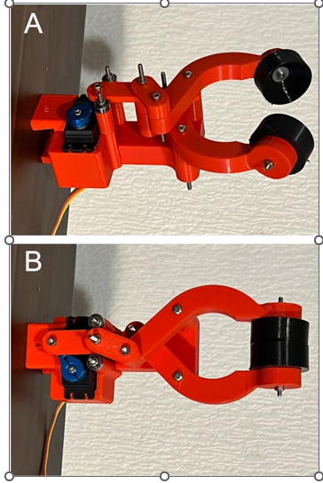
Figure 7. PLA+ 3D printed RC servo actuated gripper with soft Ninja flex endpoint cups. The gripper is shown in open (panel A) and closed (panel B) configurations.
4. Forward kinematics
4.1. Kinematic analysis of the arm
In robotic arms that operate with actuators capable of torque control, the examination of arm dynamics is an important and valuable exercise. In our design, we utilize worm-drive motors. Due to the high levels of friction introduced by this type of drive mechanism, which essentially results in a non-back-drivable system, worm drive motors are not conducive to building systems that effectively implement torque control. As a result, in our design, we do not employ torque control for the motors. Instead, we directly implement kinematic positional control of joint angles. For this reason, our analysis focuses on the forward and inverse kinematics of the mechanism as well as the Jacobian-based relationships between motor rotational velocity and endpoint velocity. Additionally, since the arm is lightweight and operates at a relatively slow speed, we also present an analysis of static force relationships using the Jacobian transpose.
4.2. Denavit-Hartenberg
Numerous textbooks on robotics offer kinematic analyses of arm structures [34–36]. For reader convenience, here we provide straightforward derivations.
Figure 8 illustrates the structure of the four links within the arm. While a straightforward derivation of the kinematics from the arm’s geometry is possible, we have chosen to employ classical Denavit-Hartenberg (DH) analysis, a method often adopted in the field of robotics. Figure 9 displays the appropriate frames for DH analysis. The corresponding DH table for the arm are presented in Table 1 and the operating range limits of the robot joints are also included.
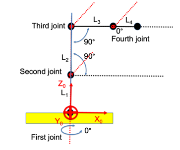
Figure 8: Default configuration.
Table 1: Denavit-Hartenberg parameters for the arm mechanism
| Link | Angle θ [°] | Min θ [°] | Max θ [°] | Angle α [°] | Radius a [mm] | Offset d [mm] |
| 1 | θ1 | -45° | 45° | 0 | 0 | 300 |
| 2 | θ2 | 35° | 145° | 0 | 300 | 0 |
| 3 | θ3 | -145° | -35° | 0 | 300 | 0 |
| 4 | θ4 | -110° | 110° | 0 | 175 | 0 |
4.3. Forward kinematics
The homogeneous transformation matrix for a classical DH-frame is given by the expression:
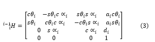
where ‘i’ is the frame, ‘c’ denotes cosine and ‘s’ sine. We note that here we use the suffix notation for a homogeneous transformation H between link frames, indicating mapping from the frame identified by the i-suffix location to the frame identified in the i-1 suffix location, that is .
In our case, the overall forward kinematic transformation for the arm is accomplished by multiplying the homogeneous matrices for the links together in the appropriate serial order, leading to the expression:
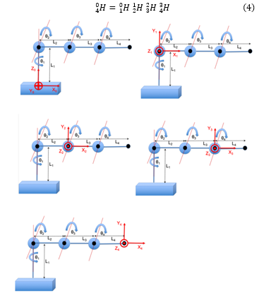
Figure 9. DH coordinate frames.
We utilize the MATLAB symbolic toolbox to evaluate the expression given in Eqn. (4), leading to the overall homogeneous transformation:
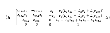
In this context, L1, L2, L3, and L4 denote the four link lengths, and we introduce the following notational simplifications for clarity: , .
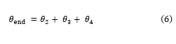
In our arm design, the angle is dependent on the final link orientation angle as well as joint angles and . That is:
The expression below just provides the endpoint location of the final link, together with its orientation angle :
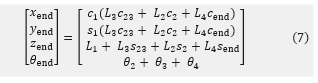
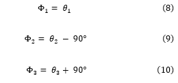
We define a neutral arm posture, as illustrated in Figure 8. Configuration of the arm can be specified by control angles that deviate from this posture. Clearly, in this state, these angles Φ1, Φ2, and Φ3 have values of zero. By inspection of Figure 8, it can be seen that Φ1 follows directly, whereas Φ2 and Φ3 are offset from and . More precisely, we calculate the control angles as follows:
4.4. Workspace of the arm
The robotic arm’s workspace is confined not only by the lengths of its links but also by the operational range of the angular joints, which are restricted due to inherent physical limits.
The primary vertical joint of the robot arm, denoted as J1, is theoretically capable of rotating from -180° to 180°. However, due to practical constraints arising from the wiring of the upper motors and encoders we chose to limit its rotation to a range between -45° and 45°. Joint J2, associated with the main upper arm link, is intrinsically able to rotate across a range from 0° to 180°. Nevertheless, physical limitations within the end-point orientation mechanism confine its rotational scope to between 35° and 145°.
Similarly, the rotation of joint J3, linked to the secondary arm drive, is constrained by the endpoint orientation mechanism, permitting rotation only within an approximate range of -35° to -145°.
To illustrate the arm’s workspace, we first generate a test dataset of random configurations of the arm. To achieve this, for each arm joint angle, we independently draw 20,000 samples from a uniform distribution with lower and upper angular limits set by the operating range of the respective joint. We then use these 20,000 random angular configurations to calculate the arm end-point positions using forward kinematics, as given by Eqn. (7). The resulting arm end-points are then plotted in 3D and displayed in three different views for clarity, as illustrated in Figure 10.
5. Differential kinematic analysis
5.1. Exploring joint and endpoint velocity relationships
The 4×4 Jacobian matrix of the arm can be used to relate its end-point velocity to joint velocity. To formulate the Jacobian requires that we find the partial derivatives of its end point position and orientation given in Eqn. (7), with respect to the arm joint angles. The Jacobian is given by the matrix expression:
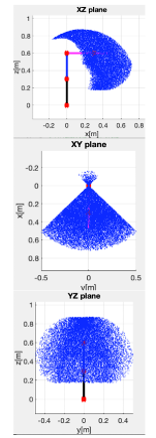
Figure 10. Workspace of the robot arm, also showing the arm displayed in its standard canonical configuration. Panel A: Side view showing the XZ axes. Panel B: Top view showing the XY axes. Panel C: Front view showing the YZ axes.
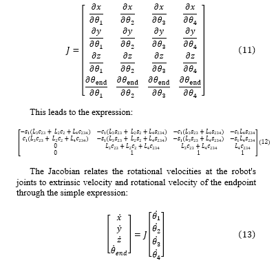
Examination of the Jacobian is informative regarding the singularities of the arm mechanism. Here we consider the case when the base rotation is zero. In this case the determinant of the Jacobian can be expressed as the relationship:
![]()
We observe that the determinant reaches zero when is either 0 or π, occurring when the third link aligns with, or rotates backwards onto the second arm link. However, such configurations are not within the operating range of the arm. Consequently, on the basis of Eqn. (13), we can employ the inverse Jacobian to compute the joint velocities as follows:
5.2. Static force relationships
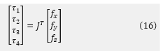
We can construct the 3×4 Jacobian by omitting the last row in Eqn. (12). Utilizing the transpose of the 3×4 Jacobian, we can establish a relationship between static joint torques – denoted – and static endpoint forces – expressed as – through the following relationships:
6. Inverse kinematics
6.1. Main rotary axis
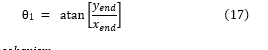
To determine the arm’s inverse kinematics, we first define the endpoint location in the base frame coordinate system as the point (xend, yend, zend). We note that in the base frame coordinate system, the arm mechanism’s first joint constitutes a rotational axis around its z-axis, specified the angle . This rotation is the sole contributor to the end-effector’s displacement along the base frame coordinate system’s y-axis, as illustrated in Figure 11. Thus, determining is relatively straightforward, given that:
6.2. Planar arm mechanism
Our attention now shifts to the remaining planar arm mechanism. We define a 2D coordinate frame in the plane of the planar arm, situating its base at the origin (0,0), and defining the end effector location by the 2D point (xp3, yp3), as depicted in Figure 12.
Referring once more to Figure 12, we observe that the x-displacement, denoted as xp3, is given by:
![]()
We note that the direction of y-axis in the planar arm frame corresponds to the direction of z-axis in base frame. However, the 2D location of the end effector, denoted as y3, must take the base height into account: Therefore, we have:
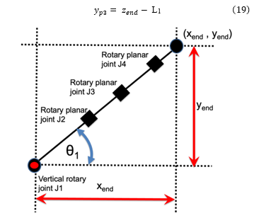
Figure 11: Top-down view of the robot arm: This perspective demonstrates the simplicity in calculating the first joint angle θ1.
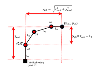
Figure 12: Side view of arm when main vertical axis joint angle is zero. The end-point of the arm in this coordinate frame is specified as the point (xp , yp), and its origin (0, 0) is located at J2.
We will shortly use the point (xp3, yp3) to calculate the 2D point (xp2, yp2), which we now consider obtaining the angles and of the remaining 2-link planar arm assembly. The cosine rule can be used to analytically derive this structure’s inverse kinematics.
As depicted in Figure 13A for the 2-link planar arm mechanism, the elbow joint is situated at point (xp1 yp1), while the upper arm joint is located at (xp2, yp2). Utilizing the Pythagorean theorem yields an expression for the length of the hypotenuse r:
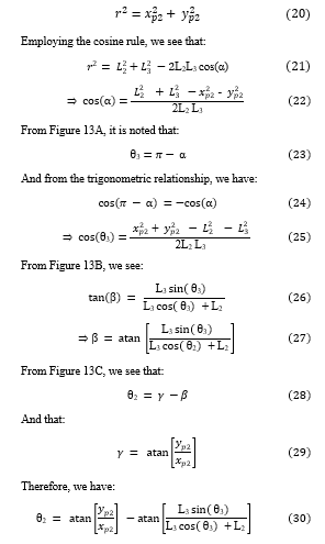
To obtain a direct expression for the inverse kinematics of the arm assembly in terms of the point (xp3 yp3), we first consider the constant orientation of the end link. In order to account for its effect, which is only a translation along the x-axis and none along the y-axis, we subtract its length from the end effector’s position and directly use its y value:
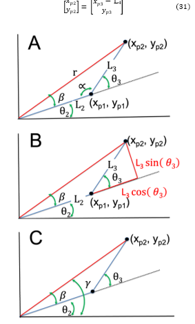
Figure 13: Schematic representation of the upper 2D parallelogram mechanism in the revolute arm: Useful for deriving inverse kinematics, the diagram illustrates the key positions, angles, and lengths.
Finally, we need to substitute the end effector location in as specified in the base coordinate frame, as defined by (xend, yend, zend), and account for the height of the first vertical axis:
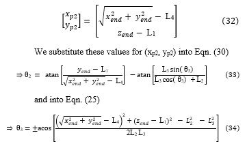
We substitute these values for (xp2, yp2) into Eqn. (30)
and into Eqn. (25)
We observe that Eqn. (34) yields two solutions and employs the value of to compute utilizing Eqn. (33). We opt for the negative solution for as it aligns with the configuration illustrated in Figure 2. Lastly, we determine using Eqn. (6):
![]()
We note that this relationship was also used to calculate the minimum and maximum values of shown in Table 1 on the basis of the minimum and maximum values of and .
7. Control electronics
7.1. Microcontroller operation
A microcontroller system, built upon the Arduino Mega platform, was designed to operate the arm and power the worm-drive motors. This microcontroller offers an ample number of digital I/O ports with interrupt capability, facilitating operation with three incremental encoders located on the back of the motors through interrupt pins. This setup allowed for effective determination of the motor positions before the gear reduction via their worm drive mechanisms. To control the robot, a USB serial connection with the Arduino Mega was used.
7.2. Motor speed regulation using H-Bridges
To operate the DC motors used in the arm, we utilized two L298N Dual H-Bridges. These components allowed precise control over both the speed and direction of all three motors. Motor voltage is set using pulse-width modulation (PWM) activation of the on-time of the H-bridges. Drive power is provided from a 24V regulated power supply.
7.3. DIN rail controller implementation
All controller components were mounted on DIN rails, providing a simple and robust construction method. Please refer to Figure 14 to see its physical implementation. The 5V supply required to power the H-Bridge was provided by the Arduino Mega. In addition, an LM2596S DC-DC Buck converter module was attached to the DIN rail, directly driven from the 24V regulated power supply, to operate accessories such as the RC servo-operated gripper mechanism.
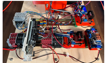
Figure 14: Controller electronics organized using DIN rail construction. The Arduino-based controller, terminal blocks, and H-bridges for the three worm drive motors can be seen mounted on the two DIN rails. A Buck controller is also shown and provides a 5V drive for the RC servo operated gripper mechanism.
7.4. Microcontroller program structure
Code was developed on the Arduino Mega to implement the kinematic control of the arm. The operation of the code consists of three distinct stages:
- Initialization and Definitions: In this stage, variables and functions utilized by the algorithm are defined and initialized. Class objects are also constructed.
- Setup: In this phase, operating variables are initialized and communications with the host PC are established.
- Poll Loop: The poll loop is an endless processing loop that is used to service the program’s needs. As well as implemented arm control, it must also service incoming messages from the host PC via a USB connection.
7.5. Microcontroller program menu
Within the poll loop, incoming commands from the serial interface are read and decoded. The available commands include:
- Manually set positive and negative rotation of individual drive motors.
- Reset encoders. This action needs to be carried out after the arm is positioned into its standard configuration, leading to calibration of the joint angles.
- Activate movement tracking along a predetermined trajectory.
- Activate point mode so can manually increment or decrement the robot’s end-point along either the x, y or z axis in extrinsic space.
- Stop all movement.
- Display help menu and view parameters.
7.6. PID controller to track target trajectories
The arm is preliminary intended to carry out point-to-point movements for pick-and-place operations. For such tasks, the arm is typically given positional targets, or trajectories, to which it is required to reach. Inverse kinematics are then used to calculate the corresponding target motor angles. To accomplish this trajectory tracking task, a position control mode was implemented. When this mode is active, motor encoders are read to estimate the arm’s joint angles, taking into considering the mechanical advantage of the worm gearing and also the drive pulley system. PID control is applied to ensure they match up with the requested joint control angles. In total there are three separate PID controllers, one for each motor. Output from the PID controllers constitutes velocity commands which make use of the H-Bridges to drive the motors.
Although the parallelogram joints and can be directly driven by the arm control angles , , the third parallelogram joint must be driven by the sum of and to achieve the desired configuration of the parallelogram.
The Proportional-Integral-Derivative (PID) gains were determined empirically through experimental trials conducted on the actual robot. Notably, the integral gain was set to zero. In the next section we present the pseudo-code for the primary controller loop.
7.7. Main controller loop pseudocode
Pseudocode for the main poll loop running trajectory tracking is shown below. This makes use of function calls to calculate inverse kinematics and implement PID control and these functions are also described with pseudocode in subsequent sections.
| Main Poll loop | ||||||||
| Result: Moves arm along target trajectory | ||||||||
| Perform Initialization of variables and trajectory | ||||||||
| while want tracking do
|
||||||||
| Call the menu object for input commands and act accordingly
Calculate time interval ‘h’ since the last update Read the desired target endpoint location (x, y, z) Call Inverse Kinematics function to get target joint angles , and Compute corresponding arm control angles , and Read the three motor actuator angles , and Call PID function with control target angle and motor angle as input motor which returns motor velocity control Call PID function with control target angle and motor angle as input motor which returns motor velocity control Call PID function with control target angle and motor angle as input motor which returns motor velocity control Generate PWM control velocities using Arduino for , & and using H-bridges apply drive to the respective worm-drive motors |
||||||||
| end | ||||||||
7.8. Inverse kinematics pseudocode
An essential aspect of the tracking process involves mapping the desired extrinsic position targets to the corresponding arm joint angles using inverse kinematics. We employ an implementation of inverse kinematics based on Eqns. (17, 33, 34), which is presented here as pseudocode in C++ style. The actual inverse kinematics code is written in C++ and makes use of a constructor to set up the link lengths L1, L2, L3. L4 and the endpoint angle in member variables. The inverse kinematics pseudocode is as follows:
| Inverse Kinematics | ||||||||
| Input: Desired target end point location (xend, yend, zend)
Link lengths: L1, L2, L3, L4 Endpoint angle: |
||||||||
| Result: Target joint angles , , , | ||||||||
| Return: IK success or fail flag
|
||||||||
| Function call
|
||||||||
| Calculate = atan2(yend, xend)
Calculate x-axis of planar arm: xp3 = sqrt (xend2 + yend2) Account for end link: xp2 = xp3 – L4 Account for base height of planar arm: yp2 = zend – L1 Calculate cos( ): c3 = (xp22 + yp22 – L22 – L32) / (2 * L2* L3) Calculate sin( 3): s3 = sqrt(1 – c32)) Check if can reach target: if ((1 – c32) < 0) return false Calculate = -atan2(s3, c3) Calculate variable k1= L2 + L3 * c3 Calculate variable k2 = -L3 * s3 Calculate = atan2(yp2, xp2) – atan2(k2, k1) Calculate = – – Succeeded reaching target so: return true |
||||||||
| end | ||||||||
7.9. PID block pseudocode
The PID function control code is written in C++. This code includes a constructor for setting up the gain parameters as member variables, a reset function which is needed to initialize the last time and last error member variables, and to reset the error integral. It also includes and a PID error block that calculates the control signal based on the target and measured joint angles. Pseudocode is for the computation of the control U is shown below.
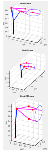
Figure 15. Arm configurations to selected targets. This visualization demonstrates how the arm accesses three distinct points on target circles within the XY, XZ, and YZ planes. The arm joint angles are computed via inverse kinematics, while the arm joint positions are computed through the application of forward kinematics
8. Arm operation
8.1. MATLAB Simulation
To test and showcase the inverse kinematics, we implemented a set of simple tracking tasks in MATLAB. We generated three distinct trajectories. Each of these trajectories is composed of 500 points, uniformly distributed around the perimeters of circles in the XY, XZ, and YZ planes. These circles, with their centers positioned at the (x, y, z) coordinates of (0.475, 0.0, 0.60) meters and a radius of 0.15 meters, comfortably fit within the robotic arm’s operational workspace. Utilizing inverse kinematics, we computed the necessary arm angles to target specific points on these circles. Figure 15 visually presents both the desired circles and the requisite arm postures to access three chosen points from each circle.
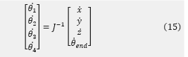
We made use of Eqn. (15), to calculate motor shafts angular velocities corresponding to the endpoint of the arm moving around the circle every 2 seconds. Figure 16 illustrates this, revealing it corresponds to an endpoint speed of 0.47 m/s. The peak joint speed was identified to be 1.64 Rad/s, which is notably beneath the maximum speed the motors are capable of achieving, 1.77 Rad/s, as denoted by Eqn. (1). It’s noteworthy that pursuing the target circle with the arm’s endpoint through inverse kinematics and calculating velocities via finite differences deliver consistent results.
Using Eqn. (16) and discounting the impact of the arm’s inherent dynamics (a simplification that holds true primarily at low movement velocities), we computed the torques at the motor shafts. These torques are required to sustain a realistic payload of 1kg while applying a force of 1Kgf in the negative x-direction. This is for endpoint positions encircling the target circle in the YZ plane. Figure 17 reveals a peak joint torque of approximately 8.56Nm. Notably, this value marginally surpasses the designated joint torque the motors can produce, which is 8.33Nm as referenced in Eqn. (2). However, this is attainable during intermittent operation.
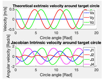
Figure 16. Arm velocity relationships: The arm’s endpoint navigates around a target circle with a 0.15 m radius, executing three full rotations within a 10-second time frame. The center of the circle coincides with the arm’s endpoint in its canonical position. Panel A: Extrinsic endpoint velocities of the arm. Panel B: Angular velocities of the arm joints
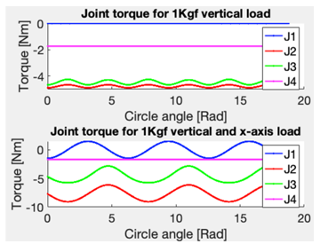
Figure 17. Simulated joint torques under combined loading conditions: Effect of simultaneous 1 Kgf horizontal and 1 Kgf vertical loads. The scenario involves the endpoint moving around a target circle with a 0.15 m radius, the center of which aligns with the endpoint of the arm in its canonical position.
8.2. Trajectory tracking using the physical robotic arm
Demonstrations of tracking around XY, XZ and YZ circles were performed using the actual physical robotic arm.
To implement tracking around square and circular trajectories, firstly target 3D trajectories were generated offline using the microcontroller and held in an array. During the trajectory tracking operation, target points were read out from the array at the appropriate time-index, and their values converted to target joint angles using the microcontroller’s implementation of the arm’s inverse kinematics.
A Proportional-Derivative (PD, i.e., PID with a zero integral gain component) controller implemented on the microcontroller was then used to ensure the motors were appropriately driven so that the target joint angles were tracked.
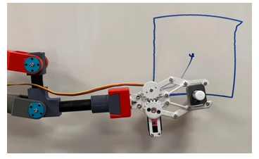
Figure 18: Arm using a low-cost commercially available gripper to hold a felt-tip marker pen and draw on a whiteboard.
8.3. Tracking using the physical robotic arm
For demonstration purposes, a simple commercial gripper was affixed to the arm’s endpoint, enabling it to grasp and subsequently release objects. Tracking around a square while holding a pen and drawing on a whiteboard is depicted in the photograph shown in Figure 18 (refer also to section 8.5 for online YouTube videos). It’s worth noting there is some overshoot in the upper right-hand corner due to friction caused by the arm pressing against the whiteboard before suddenly slipping. Future improvements to the controller should address this issue.
8.4. Pick and place operation using the physical robotic arm
We also demonstrate the pick-and-place teleoperation of the arm through a berry-picking task. This task entailed the remote control of the arm to harvest artificial berries from an artificial bush. Both the berries and the bush were designed for a study that evaluated gripper mechanisms under direct human operator control [33].
The teleoperation is implemented as a variant of the previous trajectory tracking task, utilizing inverse kinematics and PID control to appropriately drive the actuating worm-gear motors. However, in this instance, rather than tracking a pre-defined trajectory, keyboard commands were used in real time to increment or decrement a stationary target position in extrinsic space. In this manner, an operator could direct the endpoint of the arm to the desired location in space. Opening and closing the gripper was implemented using an RC servo tester unit.
8.5. YouTube demonstrations of arm simulations and operation
Video demonstrations of these real robot tasks are available on our YouTube channel, “Robotics, Control, and Machine Learning,” within the playlist “Design and prototyping of a 3DOF worm-drive robot arm.” The playlist is accessible directly via the following link:
9. Discussion
9.1. Summary
In this project, we engineered a lightweight robotic arm mechanism, capable of operating in a three-dimensional workspace, primarily designed with the agricultural industry in mind. However, it could also find applications in various other industries, as well as providing a platform suitable for education in robotics.
The integration of a two-dimensional planar mechanism, affixed to a vertical rotary axis, achieves comprehensive 3D spatial coverage. The parallelogram design takes inspiration from the vBOT robotic manipulandum, a research instrument utilized to explore human sensorimotor control in arm movements [37].
We opted for worm-drive actuation to ensure that static postures could be sustained without necessitating an active motor drive, thereby mitigating power consumption. By leveraging off-the-shelf and light-weight structural components, the design not only becomes cost-effective but due to its minimal moving mass, also remains inherently safe particularly when operated in close proximity to individuals. Overall, this culminates in a design that is easy to fabricate, low-cost, lightweight, and is power-efficient.
9.2. Extension of previous work
The current work extended a previous prototype design in several important ways. An additional vertical rotary axis is added, enabling the original planar arm mechanism to rotate and thus operate in a 3D workspace. The kinematic analysis is expanded, and forward, inverse, and differential kinematics for the new 3D arm structure are derived. Furthermore, the former planar arm support structure has been fully redesigned, and we now incorporate 3D-printed pulleys on the arm itself, replacing the previous cumbersome aluminum pulleys. Finally, in the results section, we present evidence of the arm’s point-to-point operation, including pick-and-place tasks, demonstrating its ability to perform practical real-world activities.
9.3. Novel contribution of the work
The novel aspects of the design arise from combining the use of 3D printing, carbon fiber sections for arm fabrication, a parallelogram planar upper arm structure that passively maintains endpoint orientation, and the use of worm gear motors.
The key features of the arm, as well as its similarities and differences with the previous prototype arm presented in [1], are summarized in Table 2.
9.4. Bill of materials and cost of the arm
The arm design incorporates numerous low-cost components, resulting in a construction that can be assembled relatively inexpensively. Table 3 presents a bill of the main materials for the project, indicating the costs of individual components as listed by online suppliers for small quantities.
The total cost of constructing a single unit (in 2023) is approximately £480, although discounts would likely apply for larger quantities. While assembly costs have not been included in this calculation, the arm, can easily be put together within a day by a single person. This assumes that the 3D printed custom parts have already been printed and are available for assembly.
Clearly, a construction cost of less than £500 makes the design competitive against many commercial arms, as well as those targeted more towards the hobby market. The former typically start at several thousand pounds per unit, while the latter are still on the order of £1000.
Table 2: Features of the new arm design highlighting differences with the previous 2D prototype
| ARM FEATURE | NEW ARM | PROTOTYPE ARM |
| SIMILARITIES IN DESIGN | ||
| Worm-drive motor actuation | Yes | Yes |
| Low weight carbon fiber upper limb construction | Yes | Yes |
| Passive end-link horizontal orientation mechanism | Yes | Yes |
| Construction makes use of low-cost off-the-shelf components wherever possible | Yes | Yes |
| Construction technique employs 3D printing for custom parts | Yes | Yes |
| DIFFERENCES IN DESIGN | ||
| Linear endpoint degrees of freedom (DOFs) of the arm in extrinsic space | 3 | 2 |
| Arm configuration | Revolute arm mechanism
|
Planar 2D mechanism |
| Dovetail end-effector attachment point | Yes | No |
| End-effector accessories | The new design integrates the use of both a commercial and a new bespoke gripper mechanism | No accessories |
| Demonstration of pick-and-place operation | Yes | No |
| Timing belt drive mechanism | Driven from custom 3D printed pillars and baseplate | Driven from baseplate |
| Forward kinematic analysis and implementation | FK derived and implemented for 4-link 3DOF arm | FK derived and implemented for 3-link 2DOF arm |
| Inverse kinematic analysis and microcontroller implementation | IK for 4-link 3DOF arm | IK for 3-link 2DOF arm |
Table 3: Main arm mechanism bill of materials indicating component costs in (as of 2023)
| DESCRIPTION | UNIT COST | NUMBER | TOTAL |
| DRIVE MECHANISM COMPONENTS | |||
| Worm-drive motor DC 24V 28RPM with Hall encoder | £35 | 3 | £105 |
| 50mm I/D 90mm O/D 20mm Thick deep-groove bearings | £10 | 1 | £10 |
| HTD 5M 24 tooth pulley | £12 | 3 | £36 |
| HTD 345 5M belt | £16 | 3 | £48 |
| ARM STRUCTURAL COMPONENTS | |||
| CF tube 16×14 x250mm | £12 | 3 | £36 |
| CF tube 16×14 x100mm | £6 | 1 | £6 |
| CF rod 8mmx250mm | £12 | 2 | £24 |
| 8mm 200mm stainless shaft | £5 | 1 | £5 |
| Aluminum flange 3mm I/D x H13 x D10 | £2 | 14 | £28 |
| M3 x 95mm bolt | £1 | 8 | £8 |
| M6 x 150mm bolt | £2.50 | 6 | £15 |
| M6 x 170mm bolt | £2.50 | 4 | £10 |
| 8mm I/D x 22mm O/D x 7mm thick bearing | £2 | 2 | £2 |
| Miniature bearings I/D 3mm x 10mm O/D x 4mm | £0.8 | 16 | £13 |
| Shaft collars 8mm | £1.5 | 2 | £3 |
| ARM CONTROLLER COMPONENTS | |||
| Arduino Mega clone | £16 | 1 | £16 |
| Dual H-Bridge Motor Drive Controller Board L298N | £2.5 | 2 | £5 |
| Buck converter to power RC servo driven accessories | £2.5 | 1 | £2.5 |
| DIN rails 300mm | £3 | 2 | £6 |
| DIN clips | £2 | 6 | £12 |
| DIN rail terminals | £1 | 22 | £22 |
| Arduino DIN rail Mount | £8 | 1 | £8 |
| 3D PRINTING MATERIAL | |||
| 1Kg roll PLA+ | £20 | 3 | £60 |
| TOTAL SUM | £ 478 | ||
9.5. Simple upgrades to the current design
In our current design, the fourth end-link consistently maintains a 0° orientation angle, resulting in a translation of the overall endpoint along the horizontal x-axis. However, alternative fixed endpoint orientations could be achieved, by adapting the design of the wrist component.
We utilized parts fabricated from PLA+ through 3D printing. While this material is a suitable choice for prototyping due to its printing ease, more sturdy and environmentally resilient materials could be seamlessly substituted for actual deployment, such as in fruit-picking applications. Potential alternatives might encompass the use of PETG, ABS, nylon, or even composite materials [33, 34].
In line with the approach adopted by an earlier prototype [1], incorporating an efficient controller that estimates motor torque by monitoring motor current would be a simple task. This feature would enable the incorporation of a safety mechanism into the controller, devised to identify unforeseen collisions. Motor current could be compared with anticipated values for a specific task, enabling automatic deactivation of the control if these limits were surpassed.
9.6. Future improvements
The current arm system employs a simple controller based on the Arduino Mega and L298N Dual H-bridges. While this cost-effective combination displays reasonable performance and is suitable for the current proof-of-concept arm design, it does exhibit significant shortcomings. The Arduino Mega’s default capability to generate a PWM operating frequency for controlling three outputs is restricted, achieving only a relatively low operating frequency of 490 Hz. Additionally, the microcontroller’s clock speed is quite slow (16 MHz), limiting the control loop update rate to around 100 Hz. Future developments of the arm will involve creating a higher-performance controller, leveraging faster, cost-effective microcontrollers such as the ESP32.
Current measurement of endpoint position using motor encoders cannot account for potential deformations or flexibilities inherent in the arm’s structure, or the slight backlash in the worm gear motors. Integrating additional angular position sensors on the arm’s joint axes, e.g., using low-cost magnetic encoders, would improve the estimation of endpoint position which could be used to improve arm operational accuracy.
Direct force sensing using force transducers would provide an effective method for the estimation of endpoint force. Although commercial industrial force transducers are prohibitively expensive, research suggests that 3D-printed sensors may provide a suitable low-cost solution to this issue [38].
Finally, it is noteworthy that in the design described here, direct-drive brushless DC motors could serve as a substitute for the current method of actuation and support force and torque control performance [39]. However, this would also incur higher motor costs and escalate power consumption, particularly during the maintenance of static arm configuration.
Conflict of Interest
The author confirms there are no conflicts of interest to disclose.
Acknowledgements
We thank Enterprise Solutions at the University of Plymouth for their financial support of this work on a project entitled, “Low-cost Compliant Robotic Arm for Fruit and Vegetable Harvesting”. We also thank our industrial partner, Fieldwork Robotics Ltd., and in particular, Martin Stoelen of Western Norway University of Applied Sciences, for their invaluable support and insightful discussions.
- I.S. Howard, “Design and prototyping of a low-cost light weight fixed-endpoint orientation planar Cobot,” in 2022 International Conference on System Science and Engineering (ICSSE), IEEE: 47–54, 2022, doi:10.1109/ICSSE55923.2022.9947353.
- T. Duckett, S. Pearson, S. Blackmore, B. Grieve, W.-H. Chen, G. Cielniak, J. Cleaversmith, J. Dai, S. Davis, C. Fox, “Agricultural Robotics: The Future of Robotic Agriculture,” UK-RAS Network, UK-RAS White Papers, 2018, doi:https://www.ukras.org.uk/wp-content/uploads/2021/01/UKRASWP_AgriculturalRobotics2018_online.pdf.
- A. Bechar, C. Vigneault, “Agricultural robots for field operations: Concepts and components,” Biosystems Engineering, 149, 94–111, 2016, doi:https://doi.org/10.1016/j.biosystemseng.2016.06.014.
- F. Chaumette, S. Hutchinson, P. Corke, “Visual servoing,” Springer Handbook of Robotics, 841–866, 2016, doi:https://doi.org/10.1007/978-3-319-32552-1_34.
- D.F. Kutz, A. Wölfel, T. Meindl, D. Timmann, F.P. Kolb, “Spatio-temporal human grip force analysis via sensor arrays,” Sensors, 9(8), 6330–6345, 2009, doi:10.3390/s90806330.
- B. Jia, A. Zhu, S.X. Yang, G.S. Mittal, “Integrated gripper and cutter in a mobile robotic system for harvesting greenhouse products,” in 2009 IEEE International Conference on Robotics and Biomimetics (ROBIO), IEEE: 1778–1783, 2009, doi:10.1109/ROBIO.2009.5420430.
- S. Gorjian, H. Ebadi, M. Trommsdorff, H. Sharon, M. Demant, S. Schindele, “The advent of modern solar-powered electric agricultural machinery: A solution for sustainable farm operations,” Journal of Cleaner Production, 292, 126030, 2021, doi:https://doi.org/10.1016/j.jclepro.2021.126030.
- I.O. for Standardization, “Robots for industrial environments–safety requirements–Part 1: robot, ISO10218‐1: 2006,” 2006.
- B. Vanderborght, A. Albu-Schäffer, A. Bicchi, E. Burdet, D.G. Caldwell, R. Carloni, M. Catalano, O. Eiberger, W. Friedl, G. Ganesh, “Variable impedance actuators: A review,” Robotics and Autonomous Systems, 61(12), 1601–1614, 2013, doi:https://doi.org/10.1016/j.robot.2013.06.009.
- G. Grioli, S. Wolf, M. Garabini, M. Catalano, E. Burdet, D. Caldwell, R. Carloni, W. Friedl, M. Grebenstein, M. Laffranchi, “Variable stiffness actuators: The user’s point of view,” The International Journal of Robotics Research, 34(6), 727–743, 2015, doi:https://doi.org/10.1177/027836491456651.
- M.F. Stoelen, R. de Azambuja, B. López Rodríguez, F. Bonsignorio, A. Cangelosi, “The GummiArm Project: A Replicable and Variable-Stiffness Robot Arm for Experiments on Embodied AI,” Frontiers in Neurorobotics, 16, 24, 2022, doi:https://doi.org/10.3389/fnbot.2022.836772.
- M.F. Stoelen, F. Bonsignorio, A. Cangelosi, “Co-exploring actuator antagonism and bio-inspired control in a printable robot arm,” in From Animals to Animats 14: 14th International Conference on Simulation of Adaptive Behavior, SAB 2016, Aberystwyth, UK, August 23-26, 2016, Proceedings 14, Springer: 244–255, 2016, doi:https://doi.org/10.1007/978-3-319-43488-9_22.
- A. De Luca, A. Albu-Schaffer, S. Haddadin, G. Hirzinger, “Collision detection and safe reaction with the DLR-III lightweight manipulator arm,” in 2006 IEEE/RSJ International Conference on Intelligent Robots and Systems, IEEE: 1623–1630, 2006, doi:10.1109/IROS.2006.282053.
- S. Haddadin, A. Albu-Schäffer, G. Hirzinger, “Safety evaluation of physical human-robot interaction via crash-testing,” in Robotics: Science and systems, Citeseer: 217–224, 2007, doi:10.15607/RSS.2007.III.028.
- A. Albu‐Schäffer, S. Haddadin, C. Ott, A. Stemmer, T. Wimböck, G. Hirzinger, “The DLR lightweight robot: design and control concepts for robots in human environments,” Industrial Robot: An International Journal, 34(5), 376–385, 2007, doi:https://doi.org/10.1108/01439910710774386.
- J.E. Colgate, W. Wannasuphoprasit, M.A. Peshkin, “Cobots: Robots for collaboration with human operators,” in Proceedings of the 1996 ASME international mechanical engineering congress and exposition, 1996, doi:https://doi.org/10.1115/IMECE1996-0367.
- W.T. Townsend, J.K. Salisbury, “Mechanical design for whole-arm manipulation,” in Robots and Biological Systems: Towards a New Bionics?, Springer: 153–164, 1993, doi:https://doi.org/10.1007/978-3-642-58069-7_9.
- K. Bodie, C.D. Bellicoso, M. Hutter, “ANYpulator: Design and control of a safe robotic arm,” in 2016 IEEE/RSJ International Conference on Intelligent Robots and Systems (IROS), IEEE: 1119–1125, 2016, doi:10.1109/IROS.2016.7759189.
- S. Haddadin, S. Parusel, L. Johannsmeier, S. Golz, S. Gabl, F. Walch, M. Sabaghian, C. Jähne, L. Hausperger, S. Haddadin, “The franka emika robot: A reference platform for robotics research and education,” IEEE Robotics & Automation Magazine, 29(2), 46–64, 2022, doi:10.1109/MRA.2021.3138382.
- S. Mick, M. Lapeyre, P. Rouanet, C. Halgand, J. Benois-Pineau, F. Paclet, D. Cattaert, P.-Y. Oudeyer, A. de Rugy, “Reachy, a 3D-printed human-like robotic arm as a testbed for human-robot control strategies,” Frontiers in Neurorobotics, 13, 65, 2019, doi:https://doi.org/10.3389/fnbot.2019.00065.
- T. Lens, J. Kunz, O. Von Stryk, C. Trommer, A. Karguth, “Biorob-arm: A quickly deployable and intrinsically safe, light-weight robot arm for service robotics applications,” in ISR 2010 (41st International Symposium on Robotics) and ROBOTIK 2010 (6th German Conference on Robotics), VDE: 1–6, 2010.
- G.A. Pratt, M.M. Williamson, “Series elastic actuators,” in Proceedings 1995 IEEE/RSJ International Conference on Intelligent Robots and Systems. Human Robot Interaction and Cooperative Robots, IEEE: 399–406, 1995, doi:10.1109/IROS.1995.525827.
- M. Quigley, A. Asbeck, A. Ng, “A low-cost compliant 7-DOF robotic manipulator,” in 2011 IEEE International Conference on Robotics and Automation, IEEE: 6051–6058, 2011, doi:10.1109/ICRA.2011.5980332.
- D. V Gealy, S. McKinley, B. Yi, P. Wu, P.R. Downey, G. Balke, A. Zhao, M. Guo, R. Thomasson, A. Sinclair, “Quasi-direct drive for low-cost compliant robotic manipulation,” in 2019 International Conference on Robotics and Automation (ICRA), IEEE: 437–443, 2019, doi:10.1109/ICRA.2019.8794236.
- M. Fernandez-Vicente, W. Calle, S. Ferrandiz, A. Conejero, “Effect of infill parameters on tensile mechanical behavior in desktop 3D printing,” 3D Printing and Additive Manufacturing, 3(3), 183–192, 2016, doi:https://doi.org/10.1089/3dp.2015.0036.
- V.H. Pinto, J. Gonçalves, P. Costa, “Model of a DC motor with worm gearbox,” in CONTROLO 2020: Proceedings of the 14th APCA International Conference on Automatic Control and Soft Computing, July 1-3, 2020, Bragança, Portugal, Springer: 638–647, 2021, doi:https://doi.org/10.1007/978-3-030-58653-9_61.
- B. Zhang, Y. Xie, J. Zhou, K. Wang, Z. Zhang, “State-of-the-art robotic grippers, grasping and control strategies, as well as their applications in agricultural robots: A review,” Computers and Electronics in Agriculture, 177, 105694, 2020.
- J. Hernandez, M.S.H. Sunny, J. Sanjuan, I. Rulik, M.I.I. Zarif, S.I. Ahamed, H.U. Ahmed, M.H. Rahman, “Current designs of robotic arm grippers: a comprehensive systematic review,” Robotics, 12(1), 5, 2023.
- F. Rodríguez, J.C. Moreno, J.A. Sánchez, M. Berenguel, “Grasping in agriculture: State-of-the-art and main characteristics,” Grasping in Robotics, 385–409, 2013.
- J.F. Elfferich, D. Dodou, C. Della Santina, “Soft robotic grippers for crop handling or harvesting: A review,” IEEE Access, 10, 75428–75443, 2022.
- E. Navas, R. Fernandez, D. Sepúlveda, M. Armada, P. Gonzalez-de-Santos, “Soft grippers for automatic crop harvesting: A review,” Sensors, 21(8), 2689, 2021.
- J. Hughes, U. Culha, F. Giardina, F. Guenther, A. Rosendo, F. Iida, “Soft manipulators and grippers: a review,” Frontiers in Robotics and AI, 3, 69, 2016.
- L. Alvarez-Hidalgo, I.S. Howard, Human evaluation of robotic grippers for berry picking, Springer Nature Switzerland, 2023, doi:https://doi.org/10.1007/978-3-031-43360-3.
- B. Siciliano, L. Sciavicco, L. Villani, G. Oriolo, “Motion control,” Robotics: Modelling, Planning and Control, 303–361, 2009, doi:https://doi.org/10.1007/978-1-84628-642-1.
- K.M. Lynch, F.C. Park, Modern robotics, Cambridge University Press, 2017, doi:10.1017/9781316661239.
- M.W. Spong, S. Hutchinson, M. Vidyasagar, Robot modeling and control, Wiley New York, 2006.
- I.S. Howard, J.N. Ingram, D.M. Wolpert, “A modular planar robotic manipulandum with end-point torque control,” J Neurosci Methods, 181(2), 199–211, 2009, doi:10.1016/j.jneumeth.2009.05.005.
- N. Hendrich, F. Wasserfall, J. Zhang, “3D printed low-cost force-torque sensors,” IEEE Access, 8, 140569–140585, 2020, doi:10.1109/ACCESS.2020.3007565.
- H. Asada, T. Kanade, “Design of direct-drive mechanical arms,” 1983, doi:https://doi.org/10.1115/1.3269106.