Resonance Coil Design for a Novel Battery Cell Balancing with using Near-Field Coupling

Adv. Sci. Technol. Eng. Syst. J. 8(5), 70–76 (2023);
 DOI: 10.25046/aj080508
In this paper, we delve into the pressing necessity for proficient battery cell balancing, an imperative in the context of the escalating adoption of renewable energy and electric vehicles. While traditional methodologies, including the passive technique, offer a straightforward and cost-effective solution, they compromise on efficiency. The active technique, though superior in efficiency, is hindered by its innate restriction of transferring energy solely to proximate cells, thus prolonging the balancing process. To address these limitations, we introduce a novel near-field coupling method centered on a meticulously designed resonant coil with an emphasis on achieving a larger Q-factor, a pivotal factor for enhanced battery cell balancing. This augmented Q-factor not only propels our approach past the passive method in efficiency but also catalyzes rapid balancing by enabling wireless energy transfer to cells regardless of their relative positioning. Validating our theoretical insights, we developed physical coil prototypes and adopted a Series-Parallel circuit configuration, steered by the resonant coil’s Q-factor. Preliminary experiments with three batteries substantiate our claim, showcasing that our proposed technique achieves cell balancing with approximately double the speed of conventional strategies.
1. Introduction
This paper is an extension of a work originally presented in ITC-CSCC 2022 [1]. Through the Paris Climate Change Agreement, major countries around the world aim to achieve Net-zero, setting their carbon emissions to ‘0’ by 2050. Among the various policies being pursued by South Korea to achieve these goals, the expansion of renewable energy and electric vehicles plays a major role [2-3]. Renewable energy serves as an alternative to fossil fuels and nuclear power, with solar and wind power at its core. However, such energy generation is intermittent depending on weather conditions, necessitating the use of an Energy Storage System (ESS). The ESS is composed of large-capacity battery packs[4], and each of these battery cells demonstrates slight discrepancies in the State of Charge (SOC) during manufacturing. This deviation tends to increase during charging and discharging processes, leading to problems in battery life and efficiency[5-6]. Battery cell balancing is a technique used to rectify these issues. On the other hand, as the proportion of electric vehicles continues to increase globally, a new environmental issue, namely the ‘problem of battery disposal,’ has been highlighted [7]. One solution to this problem that is actively researched involves recycling spent batteries to create ESS [8-9]. In this context, the battery cell balancing technology is recognized as playing a crucial role in maximizing the efficiency and lifespan of ESS.
However, the conventional battery cell balancing, as discussed in Section 2, has limitations. As the proportion of renewable energy and electric vehicles continues to expand, there is a growing need for faster and more efficient battery cell balancing techniques. Therefore, in this paper, we propose a novel battery cell balancing method and evaluate its performance.
2. Conventional Battery Cell Balancing
Traditional cell balancing can be divided into passive battery cell balancing and active battery cell balancing. The passive type connects resistors to the battery to expend energy for balancing, while the active type connects capacitors, inductors, or transformers to the battery to transfer energy to adjacent batteries for balancing [10-13].
2.1. Passive Battery Cell Balancing
The passive type, which exhausts energy from the batteries with resistors, is based on the battery with the lowest State of Charge (SOC). This method is widely used due to its simple circuit and low cost. However, it has several drawbacks: it wastes energy leading to low efficiency, it generates heat making it prone to fire, and it can’t perform balancing during discharge operation. Therefore, it is not suitable for high-efficiency battery cell balancing. Figure 1 (a) illustrates a switching shunting resistor method of the passive type, where all switches are controlled identically or individually depending on the SOCs of the batteries.
2.2. Active Battery Cell Balancing
The active type transfers energy from cells with a relatively high SOC to those with a lower SOC. While it’s more efficient than the passive type, its circuit is complex, control is difficult, and it only allows balancing between adjacent cells, which slows down the balancing speed. Hence, it is not suitable for high-speed battery cell balancing. Figure 1 (b) shows a switching capacitor method of the active type. This method is a simpler and cheaper option within the active type, but if the cells with the highest and lowest SOCs are assumed to be at the ends of the circuit, more switches need to be controlled, leading to a longer time needed for balancing. Other methods to overcome this issue have complicated circuit configurations or high costs.

Figure 1: Conventional battery cell balancing
2.3. Proposal Battery Cell Balancing
As such, conventional battery cell balancing methods are not suitable for high-speed, high-efficiency applications due to their respective disadvantages. Table 1 summarizes the characteristics, advantages, and disadvantages of typical conventional battery cell balancing methods. It shows that passive type is not suitable for high efficiency, and active type is not suitable for high speed. Therefore, a novel battery cell balancing method, which is more efficient than the passive type and faster than the active type, is needed to overcome the disadvantages of conventional methods. This paper proposes a novel battery cell balancing method that uses near-field coupling for balancing.
Table 1: Summary of typical conventional battery cell balancing
| category | passive type | active type | |||
| method | shunt
resistor |
switching
resistor |
switching capacitor | inductor | Proposal |
| devices used | n resistors | n switches and resistors | n-1 capacitors and 2n switches | PWM | N+1 coils and N Rectifiers |
| advantage | simple circuit and
low cost |
simple circuit and low cost | reasonable balancing speed | Fast balancing &
Reasonable efficiency |
|
| disadvantage | low efficiency and
safety issue |
slow balancing speed | low efficiency & high cost | high cost | |
3. Near-Field Coupling Battery Cell Balancing
The new battery cell balancing method proposed in this paper utilizes ‘Near-Field Coupling’. This method enables selective cell balancing by transmitting energy to specific cells. ‘Near-Field Coupling’ is a method of transmitting energy between objects in close proximity using a magnetic resonance method. The resonance frequency selected for this method is 13.56MHz in the ISM band (Industrial Scientific Medical Band). Figure 2 illustrates the circuit of the proposed method. When the State of Charge (SOC) of battery B1 is lower than that of B2 and B3, the transmitter’s capacitor is variably adjusted to achieve impedance matching with the receiver of B1’s battery. The energy transmission continues until the SOC of B2 and B3 matches that of B1.
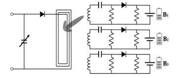
Figure 2: Proposed battery cell balancing with using near-field coupling
This proposed method is more efficient than the conventional passive type. The passive type consumes energy, leading to low efficiency, particularly because the balancing is based on the battery with the lowest SOC. However, the proposed method is more efficient because it supplements energy rather than wasting it. The energy efficiency of wireless power transmission can be divided into transmitter efficiency, receiver efficiency, and coil efficiency. With the transmitter efficiency being less than 80%, receiver efficiency at 95%, and coil efficiency less than 85%, the combined overall efficiency can reach approximately 64.6%[14-15]. This makes the proposed method more suitable for high efficiency than the passive type.
Additionally, the proposed method is faster in balancing speed than the active type. The primary reason for the slower balancing speed of the active type is because it can only transfer energy to adjacent batteries. On the other hand, our proposed method allows energy transfer even to relatively distant cells by variably adjusting the transmitter’s capacitor to achieve impedance matching with a specific receiver. This results in a faster balancing speed than the active type.
4. Impedance Matching
Impedance serves as a measure of electrical flow resistance, and impedance matching refers to all methods aimed at reducing reflection caused by differences in impedance between the input and output terminals. That is, the more closely the impedances of both terminals are matched, the more the reflection due to the impedance difference reduces, leading to less energy loss and higher efficiency[16]. Such impedance matching techniques enable selective cell balancing. By designing so that the impedance matches with a specific battery and differs from other batteries, it is possible to deliver energy only to the desired cells. The proposed method to implement this involves differentiating the mutual inductance and coupling coefficient between the transmitter and each receiver depending on the location of the receivers, based on the transmitter. This leads to unique impedance differences, enabling the selection of specific receiver cells.
4.1. Mutual Inductance
Mutual inductance is a value that represents the magnetic field interaction between two coils. As shown in Figure 3, When the current flowing through a coil changes, the magnetic field passing through that coil also changes.
This change induces an electrical change in an adjacent coil, and this interaction is referred to as mutual inductance. This varies according to distance, coil orientation, and position, leading to each battery cell having a unique value.
4.2. Coupling coefficient
The coupling coefficient is calculated using the mutual inductance and the inductance of the coil itself, and represents the efficiency of energy transfer between two coils. The higher the coupling coefficient, the higher the energy transmission efficiency, so it’s crucial to adjust the coupling coefficient appropriately. This also varies according to cell distance, similar to mutual inductance.
![]()
Through such impedance matching, the energy transmission efficiency between battery cells can be increased, and based on this, efficient cell balancing can be implemented.
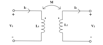
Figure 3: Mutual inductor circuit
5. Transmitter and Receiver Coil Design
Coil patterns can be designed in various forms such as square, circular, or hexagonal. However, in this study, we used the square pattern for easy modeling, based on the previous research which states that the difference between patterns is not significant at the frequency of 13.56MHz utilized in this research[1]. Furthermore, we decided on an LC circuit configuration suitable for selective battery cell balancing according to the Q-factor.
5.1. Q-factor
As shown in Figure 4, the Q-factor, defined by equation (2), represents the ratio of the resonance frequency to the 3dB bandwidth, defined as the difference between the higher frequency and the lower frequency , situated 3dB below . For effective cell balancing application, a sufficiently large Q-factor is indispensable, signifying reduced insertion loss at specific frequencies and significant increase in insertion loss with minor frequency deviations. This narrow bandwidth impedance matching is vital for the proposed selective cell balancing approach. Analyzing equations (3) and (4), it’s evident that for a consistent resonance frequency, a series LC circuit demands a larger inductance for a heightened Q, while a parallel LC circuit requires a smaller inductance for the same effect.
Given the physical constraints like battery size and coil diameter, the receiver coil was designed with a parallel configuration, where a reduced inductance yields a higher Q. Conversely, to ensure efficient energy transmission via impedance matching, the transmitter coil, designed in a series configuration, incorporates a larger inductance for an enhanced Q. This culminated in the LC circuits for both transmission and reception units being structured as Series-Parallel (SP).
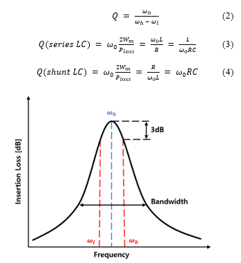
Figure 4: Q-factor in resonance circuit
Building on the crucial role of the Q-factor, the transmitter was crafted with an increased inductance, embodying a series LC circuit, fine-tuned for selective cell balancing. In parallel, the receiver was architected with diminished inductance, aligning with a parallel LC circuit, to cater to the same balancing purpose. Factors like pattern spacing, internal and external diameters, and thickness play pivotal roles in determining coil inductance. For instance, in Figure 5, pattern spacings for the transmitter and receiver coils were fixed at 1mm and 2mm respectively, echoing past research indicating augmented inductance with reduced spacing. Coil measurements in this study were not merely based on theoretical derivations; instead, they were corroborated through actual coil measurements and simulations, ensuring accuracy by accounting for potential production discrepancies.
5.2. Coil Design
By leveraging the Q-factor, it was ascertained that the inductance of the transmitter coil can be designed to be larger, ensuring that the serial LC circuit configuration is suitable for selective cell balancing. Conversely, by designing the inductance of the receiver coil to be smaller, it was confirmed that the parallel LC circuit configuration is suitable for selective cell balancing. Figure 6 presents the blueprint of the transmitter and receiver coils designed using 3D EM Simulation, as well as the fabricated PCB. (a) Represents the transmitter coil, and (b) represents the receiver coil.
The inductance of the coil is determined by various variables as shown in Figure 6, and the inductance changes even if only one of these conditions changes. The smaller the pattern spacing ‘s’ of the transmitter and receiver coil, the larger the inductance; therefore, the transmitter was designed with 1mm and the receiver with 2mm. Similarly, the smaller the internal diameter ‘Di’, the larger the inductance; thus, the transmitter was designed with 1mm and the receiver with 5mm. As can be seen from Figure 6, considering the size of the battery, the receiver’s outer diameter ‘Do’ was 20x19mm, while the transmitter, considering the size of the receiver, was 81x31mm. The thickness ‘w’ was designed to be the same at 1mm. There are various papers that infer inductance values using these variables[17-18], but in this paper, the inductance is inferred by comparing the actual measurement results of the coil with the simulation.
5.3. De-embedding
Circuits that use RF (Radio Frequency), such as 13.56MHz, cannot be measured for voltage and current like normal circuits. This is because as the frequency increases, the size of the wavelength decreases, and the voltage and current measurement values change depending on the circuit location. Therefore, RF circuits should use S-parameters, which interpret the circuit as a ratio of output voltage to input voltage, and in this paper, the proportion of the input signal reaching the output port was measured for efficiency verification.
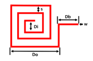
Figure 5: Coil variables
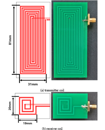
Figure 6: Transmitter and receiver coil designed using 3D EM Simulation, as well as the fabricated PCB
To measure S-parameters, an NA(Network Analyzer) was used. For the accuracy of the measurement results, the NA’s own calibration function is used to remove error components, and there are standardized methods such as SOLT(Short, Open, Load, Through), TRL(Through, Reflect, Line). In this paper, an SOLT calibration kit was used, and components such as phase delay that are not removed by general correction should be further corrected through de-embedding. De-embedding is not a standardized method like ordinary correction, so it must be conducted according to the research environment. When the circuit in the open state is represented as a Smith chart, it is indicated in the center to the right like the red dot in Figure 7, and the degree of phase delay can be understood by arbitrarily opening the fabricated transmitter and receiver PCB coil and comparing it with the measurement. The transmitter and receiver PCB coil data measured with the NA was adjusted in the simulation so that the electrical length of the ideal Transmission Line came out as in Figure 7. Figure 8 shows the result, with the blue plot being the result measured with the NA and the red plot being the result adjusted for electrical length. Figure 9 is the result of the transmitter and receiver de-embedding, and including up to the transmission line, it becomes an inductor model with phase delay removed. (a) is the result of transmitter de-embedding with an electrical length of –17.4° at 1GHz. (b) is the result of receiver de-embedding, changing the electrical length to –18.5°. Therefore, by applying the electrical length obtained through the de-embedding of the transmitter and receiver to the measurement results, accurate results with phase delay removed can be obtained.
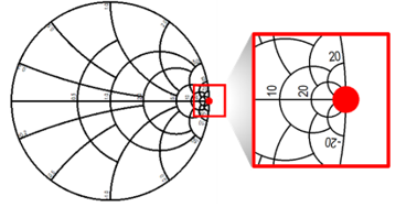
Figure 7: Open circuit on Smith chart
5.4. Inductance inference
Figure 10 shows the results of comparing the corrected measurement results through the transmitter’s de-embedding, 3D EM Simulation, and Schematic 2600nH. By comparing the phase using the s-parameter and Smith chart, there was an error of less than 3% at 13.56MHz, which makes it possible to represent the coil with one inductor of the Schematic. The receiver was compared with 130nH, and the results were similar to the transmitter. Figure 10 shows the results of comparing the measurement results of the LC circuit determined through modeling of the transmitter and receiver and the inferred LC circuit. The schematic circuit of the resonant circuit in this application is shown in Figure 11.
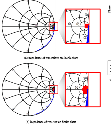
Figure 8: Transmitter and receiver coil open state measurement results(blue) electrical length adjusted results(red)
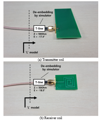
Figure 9: De-embedding of transmitter/receiver coil
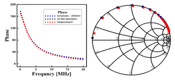
Figure 10: Transmitter de-embedding, 3D EM Simulation and Schematic 2600nH comparison results, error of less than 3% at 13.56MHz
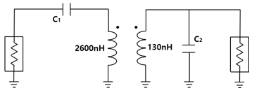
Figure 11: The schematic of measured resonance coils
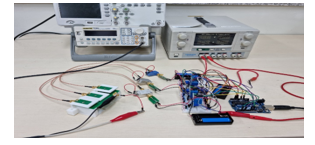
Figure 12: Cell balancing measurement set-up
5.5. Cell balancing measurement
Figure 12 shows an experiment with three battery cells with the proposed near-field coupling. One of the three cells has less charge than the other two. Figure 13 compares the regular balancing results with the balancing results obtained by implementing Near-Field Coupling using the coils and inferred capacitance modeled through this paper. The X-axis is time and the Y-axis is the voltage difference with the reference battery. The red graph represents the regular balancing results, and the blue graph represents the balancing results with added Near-field. Assuming that balancing was successfully achieved when the voltage difference with the reference battery decreased to less than 1%, the regular balancing took about 248 minutes, while the balancing with added Near-Field took about 121 minutes, nearly twice as fast as the former.
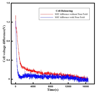
Figure 13: Cell voltage difference with and without near-field coupling
6. Conclusion
Our study confirmed that configuring the transmitter with a serial LC circuit and the receiver with a parallel LC circuit, as determined through the Q-factor, is more suitable for selective battery cell balancing. The coil of the receiver was constructed taking into account the battery size, which consequently determined the size of the transmitter coil. After the coil construction, uncorrected parasitic components were eliminated through additional correction processes such as de-embedding. Additionally, the electrical length of the transmitter coil’s t-line was adjusted to -17.4° at 1GHz and the receiver coil to -18.5° to remove phase delay.
A comparison of the more accurate measurement results obtained through de-embedding, 3D EM Simulation, and Schematic with the s-parameter and Smith chart revealed less than 3% error at 13.56MHz. As the Schematic was compared using a single inductor, it was confirmed that the coil to be produced could be represented by a single inductor. Accordingly, we inferred that the transmitter coil was 2600nH and the receiver coil was 130nH. A simple test of cell balancing with three battery cells using the proposed method confirms that cell balancing is achieved compared to no cell balancing. The results of this experiment confirm that there is not enough unwanted coupling between the coils
Conflict of Interest
The authors declare no conflict of interest.
Acknowledgment
This Research was supported by Research Funds of Mokpo National University in 2022
- J. Jeon, W. Park, S. Pyo and D. Lee, “Coil design and de-embedding for a novel cell balancing circuit using near-field coupling,” 2022 37th International Technical Conference on Circuits/Systems, Computers and Communications (ITC-CSCC), 546-548, 2022, doi: 10.1109/ITC-CSCC55581.2022.9895073.
- A. Qazi et al., “Towards Sustainable Energy: A Systematic Review of Renewable Energy Sources, Technologies, and Public Opinions,” in IEEE Access, 7, 63837-63851, 2019, doi: 10.1109/ACCESS.2019.2906402.
- S. Thangavel, D. Mohanraj, T. Girijaprasanna, S. Raju, C. Dhanamjayulu and S. M. Muyeen, “A Comprehensive Review on Electric Vehicle: Battery Management System, Charging Station, Traction Motors,” in IEEE Access, 11, 20994-21019, 2023, doi: 10.1109/ACCESS.2023.3250221.
- X. Xu, M. Bishop, D.G. Oikarinen and C. Hao, “Application and modeling of battery energy storage in power systems,” CSEE journal of power and energy system, 2(3), 82-89, 2016, doi: 10.17775/CSEEJPES.2016.00039
- J. Shen, S. Dusmez and A. Khaligh, “Optimization of Sizing and Battery Cycle Life in Battery/Ultracapacitor Hybrid Energy Storage Systems for Electric Vehicle Applications,” in IEEE Transactions on Industrial Informatics, 10(4), 2112-2121, 2014, doi: 10.1109/TII.2014.2334233.
- Q. Ouyang, W. Han, C. Zou, G. Xu and Z. Wang, “Cell Balancing Control For Lithium-Ion Battery Packs: A Hierarchical Optimal Approach,” in IEEE Transactions on Industrial Informatics, 16(8), 5065-5075, 2020, doi: 10.1109/TII.2019.2950818.
- D. L. Thompson, J. M. Hartley, S. M. Lambert, M. Shiref, G. D. J. Harper, E. Kendrick, P. Anderson, K. S. Ryder, L. Gaines and A. P. Abbott, “The importance of design in lithium ion battery recycling – a critical review” Green Chem, 22, 7582-7584, 2020, doi: 10.1039/D0GC02745F
- M. A. Hannan, M. M. Hoque, A. Hussain, Y. Yusof and P. J. Ker, “State-of-the-Art and Energy Management System of Lithium-Ion Batteries in Electric Vehicle Applications: Issues and Recommendations,” in IEEE Access, 6, 19362-19378, 2018, doi: 10.1109/ACCESS.2018.2817655.
- E. Hossain, D. Murtaugh, J. Mody, H. M. R. Faruque, M. S. Haque Sunny and N. Mohammad, “A Comprehensive Review on Second-Life Batteries: Current State, Manufacturing Considerations, Applications, Impacts, Barriers & Potential Solutions, Business Strategies, and Policies,” in IEEE Access, 7, 73215-73252, 2019, doi: 10.1109/ACCESS.2019.2917859.
- J. Qi and D. Dah-Chuan Lu, “Review of battery cell balancing techniques,” 2014 Australasian Universities Power Engineering Conference (AUPEC), 1-6, 2014, doi: 10.1109/AUPEC.2014.6966514.
- M. Daowd, N. Omar, P. Van Den Bossche and J. Van Mierlo, “Passive and active battery balancing comparison based on MATLAB simulation,” 2011 IEEE Vehicle Power and Propulsion Conference, 1-7, 2011, doi: 10.1109/VPPC.2011.6043010.
- Das, Utpal Kumar, et al. “Advancement of lithium-ion battery cells voltage equalization techniques: A review.” Renewable and Sustainable Energy Reviews 134, 110227, 2020, doi: 10.1016/j.rser.2020.110227.
- Diao, Weiping, et al. “Active battery cell equalization based on residual available energy maximization.” Applied energy 210, 690-698, 2018, doi: 10.1016/j.apenergy.2017.07.137
- A. N. Laskovski and M. R. Yuce, “Class-E oscillators as wireless power transmitters for biomedical implants,” 2010 3rd International Symposium on Applied Sciences in Biomedical and Communication Technologies (ISABEL 2010), 1-5, 2010, doi: 10.1109/ISABEL.2010.5702913.
- G. Lee, B. H. Waters, B. J. Mahoney, J. R. Smith and W. S. Park, “An investigation of cross-coupling for magnetically coupled wireless power transfer,” 2013 Asia-Pacific Microwave Conference Proceedings (APMC), 80-82, 2013, doi: 10.1109/APMC.2013.6695197.
- T. C. Beh, M. Kato, T. Imura, S. Oh and Y. Hori, “Automated Impedance Matching System for Robust Wireless Power Transfer via Magnetic Resonance Coupling,” in IEEE Transactions on Industrial Electronics, 60(9) 3689-3698, 2013, doi: 10.1109/TIE.2012.2206337.
- K. Chen and Z. Zhao, “Analysis of the Double-Layer Printed Spiral Coil for Wireless Power Transfer,” in IEEE Journal of Emerging and Selected Topics in Power Electronics, 1(2), 114-121, 2013, doi: 10.1109/JESTPE.2013.2272696.
- U. -M. Jow and M. Ghovanloo, “Design and Optimization of Printed Spiral Coils for Efficient Transcutaneous Inductive Power Transmission,” in IEEE Transactions on Biomedical Circuits and Systems, 1(3), 193-202, 2007, doi: 10.1109/TBCAS.2007.913130.