Feedback Controller for Longitudinal Stability of Cessna182 Fixed-Wing UAVs

Adv. Sci. Technol. Eng. Syst. J. 8(5), 17–27 (2023);
 DOI: 10.25046/aj080503
Unmanned aerial vehicles (UAVs) are becoming increasingly popular for both civil and military applications. Unmanned aerial vehicles can be categorized into two categories: rotary-wing and fixed-wing. Due to its capacity to fly long distances and carry substantial payloads, fixed-wing UAVs are gaining popularity and are currently utilized for various tasks. However, when confronted with disturbances such as weather or wind gusts, fixed-wing UAVs can rapidly lose stability, leading to a loss of lift and stalling. Consequently, it is vital to ensure the stability of fixed-wing UAVs. For the longitudinal stability management of a fixed wing unmanned aerial vehicle, the design and modeling of a feedback controller, including a PI controller, PID controller, and Fuzzy logic controller, are discussed in this article. MATLAB/SIMULINK©2021 will be used to design the control system and compare the response of each controller during the simulation. The controller’s response to various input formats will indicate its capacity to regulate the system’s behavior. Our results indicate that the fuzzy logic controller was superior to the PI and PID controllers at controlling the system’s response according to the desired or input behavior.
1. Introduction
Unmanned aerial vehicles (UAVs) are becoming increasingly popular in a variety of civil and military applications, including aerial photography, shipping and delivery, geo-graphic mapping, disaster management, precision agriculture, search and rescue, weather forecasting, wildlife monitoring, law enforcement, and entertainment [1–3]. Unmanned aerial vehicles are small aircraft without a pilot on board. They can be remotely commanded and operated to accomplish operations in inaccessible and extremely dangerous regions. Unmanned aerial vehicles can be categorized into two basic categories: rotary-wing and fixed-wing [4]. Due to their capacity to fly long distances and carry heavy payloads, fixed-wing UAVs are currently gaining popularity and are employed for a variety of tasks [5]. Yet, fixed-wing UAVs quickly lose their stability when disturbances arise (weather or wind gusts). The instability of unmanned aircraft will cause the wings to lose lift, resulting in the stalling of fixed-wing UAVs [2,6–8]. Thus, the fixed-wing UAV’s stability is vital.
Accidentally, Lion Air Indonesia’s Boeing 737 MAX passenger aircraft crashed into the ocean in October 2018, resulting in 189 fatalities. Additionally, Ethiopian Airlines’ Boeing 737 MAX caused 157 deaths in March 2019 [9]. Clearly, the breakdown of the flight control system caused the airplane to crash. The error-generating automatic flight control system is known as the Maneuvering Characteristics Augmentation System (MCAS) [10]. MCAS is a Boeing Company-developed system fitted in Boeing 737 MAX aircraft. MCAS is a mechanism that aids in the maintenance of stopped flights caused by an excessive angle of attack. MCAS is software coupled to the sensor that measures the angle of attack of an aircraft. The resultant MCAS mistake is the result of a faulty measurement of the rise of impact, in which the system calculates the impact angle to be greater than it actually is. The MCAS is activated when the angle of attack is greater than the angle of attack set by the system. This causes the elevator to adjust the aircraft to a progressiveMCASly decreasing angle when the pilot detects a change in the aircraft’s pitch angle. The MCAS problem causes the plane to crash. Based on actual events aboard the Boeing 737 MAX, the significance of flight control systems in actual aircraft during flight is emphasized. Therefore, flight control systems are essential for unmanned aircraft. It relates directly to flight control and safety.
The stability of fixed-wing UAVs can be broken down into three categories: directional stability, lateral stability, and longitudinal stability, with longitudinal stability being an essential type. It relates to the nose-up or nose-down position, takeoff or landing, and direct flying altitude of the UAV.
Fixed-wing UAVs employ a standard industrial feedback controller to reduce UAV expenses, such as a Proportional, Integral, Derivative, Proportional-Integral, and proportion-al-derivative controller, Proportional-Integral-Derivative controller, etc. [7,8,11]. Commercial controllers such as the Pixhawk and Paparazzi are commonly utilized in the flight control system of fixed-wing UAVs [4,12]. This present work describes control systems for fixed-wing UAVs.
In this study, the longitudinal stability management of a fixed wing unmanned aerial vehicle is constructed and simulated using a feedback controller comprising PI controller, PID controller, and fuzzy logic controller. MATLAB/SIMULINK©2021 will be used to simulate the control system and compare the responses of each controller. Modeling of aviation systems is explained in this study’s summary. P Controller, I Controller, D Controller, PI Controller, PID Controller, and Fuzzy Logic Controller define the feedback controller. In the last section, the design of the control system is implemented, and MATLAB/SIMULINK©2021 simulation results are presented.
2. Aircraft System Modeling
The movement of a fixed wing unmanned aerial vehicle can be divided into three actions according to the imaginary rotation around the X, Y, and Z axes: roll, pitch, and yaw [8], as shown in Figure 1.
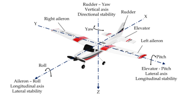
Figure 1: The movement of fixed-wing UAV.
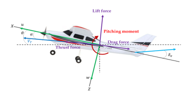
Figure 2: Pitch movement of fixed-wing UAV.
Pitch is the nose up or down of fixed-wing UAVs. It revolves around the Y-axis, an imaginary axis that goes from one wing tip to the other. It is controlled by a control surface known as an elevator, which is mounted on an empennage (horizontal stabilizer); when the elevator turns up and down (i.e., angle of the elevator: ), which causes a pitch angle: as shown in Figure 2.
The pitch of the fixed-wing UAV can be written as a transfer function. In this research, the pitch transfer function of the fixed-wing UAV can be written as a transfer function, as shown in equation 1 [6,7,13].
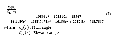
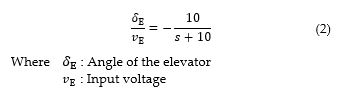
Equation 1 is a model of a fixed-wing Cessna182 UAV, with a ratio of 1:6.65 compared to a real scale, of which the fundamental dynamics of a mathematical model are similar to the real-sized aircraft. The wingspan of the model is 5.4135 ft. The dynamic of the pitching control system includes an actuator that can force the control surface to move as needed. The mathematical model used to control the elevator up and down is expressed in equation 2 [6,7,13].
3. Feedback controller
Many systems in modern industries and other systems need a controller, such as an automobile steering control system, speed control systems, temperature control systems, tracking systems, flight control systems, etc. A controller controls the process or plant that responds to the method according to the desired output response. The control system can be divided into two systems 1) an Open-loop control system and 2) a Closed-loop control system.
The open-loop control system [12] is used in processes that do not require much control precision. Therefore, it is a process that does not require a back-measurement or feedback signal to be used to calculate constants for use in control. An open control process has system components, as shown in Figure 3. The application of the open-loop control system, such as fan control systems, washing machine control, etc.
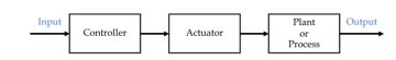
Figure 3. Open-loop control system.
A closed-loop control system [14,15] or feedback control (see Figure 4) is a controller in which the actual signal received from the system is measured and compared with the desired output signal to calculate errors. The error can be used to determine the system control constants to adjust the system to the desired output. The block diagram of the closed-loop control system is shown in Figure 5.
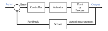
Figure 4. Closed-loop control system or feedback control system.
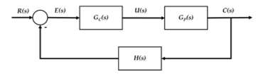
Figure 5. Block diagram of a closed-loop control system.
where R(s) : Input signal
E(s) : Error signal
GC(s) : Transfer function of the controller
U(s) : Control signal
GP(s) : Transfer function of plant or process
C(s) : Actual response signal
H(s) : Transfer function of the measurement
sensor
General controllers for closed-loop control systems can be divided into Proportional-Integral (PI) controllers, Proportional-Derivative (PD) controllers, and Proportional-Integral-Derivative (PID) controllers. These controllers have used various industrial systems such as temperature, pressure, chemical, and vehicle manufacturing. The type of controller will have a different effect on the system response. Selecting a control type in the control design will depend on the response requirements of that system. The controllers can be divided into the following types.
3.1. P-Controller
A proportional controller [16] (P controller) is a control that determines the controller’s gain or the proportion of the output signal to the input signal of the controller. The proportional controller has proportional gain to be used as an extension of the controller’s input signal. If the proportional gain is high, the system will have a fast response. The result is that the response has an oscillation. On the other hand, when the proportional gain is low, the system will slowly respond. The proportional equation of the proportional control system can be found in equation 3.
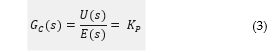
where : Proportional Gain.
3.2. I-Controller
An integral controller is a working principle of controlling the output signal by signal integration. The integral controller can be described in equation 4.
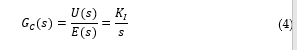
where : Integral Gain
3.3. D-Controller
A derivative controller is a control that represents the derivation of the input signal of the controller. The derivative controller can be described in equation 5.
![]()
3.4. PI-Controller
A proportional-Integral [16] (PI) controller consists of a proportional or “P” controller and an integral or “I” controller. The P controller can be found in equation 6.
3.5. PID-Controller
The proportional integral derivative controller combines the proportional, integral, and derivative controllers shown in equation 7.
Each controller has a different behavior, which can be summarized in Table 1.
In the control process, the gain must be selected according to the instability of the process. Select the controller gain that can be obtained from the Ziegler–Nichols method [17–19]. The procedure for finding the controller gain is as follows: The first step is to set KI and KD to the value 0, then increment KP from zero until the maximum value is reached, resulting in KU (Ultimate Gain). The system output will have a fixed vibration with the oscillation period or PU. As shown in Table 2, the Ultimate gain (KU) and Oscillation period (PU) can be used to calculate the controller gain (KP, KI, and KD).
Table 1: Characteristics of PID Gains KP, KI, and KD.
| Characteristic | |||
| Rise time | Decreases | Minimal Decrease | Minimal Decrease |
| Settling time | Minimal Decrease | Increase | Decrease |
| Overshoot | Increase | Increase | Decrease |
| Steady-state error | Decrease | Decrease | No impact |
| Stability | Decrease | Decrease | Increase |
Table 2: Ziegler–Nichols method using Ultimate gain (KU) and Oscillation period (PU).
| Controller | |||
| Proportional (P) | – | – | |
| Proportional-integral (PI) | – | ||
| Proportional- integral- derivative (PID) |
3.6. Fuzzy Logic Controller
A fuzzy logic controller is a type of feedback controller that can be applied to a wide variety of systems [13,20–26]. Due to the ability to control nonlinear systems, complex systems Include systems that require immediate response (Real-time system) by a fuzzy logic controller is a controller that uses reasoning and decision-making principles similar to human decision-making with a work process structure as shown in Figure 6, which consists of four components as follows:
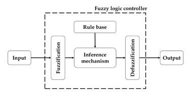
Figure 6: Fuzzy logic controller architecture.
- Fuzzification It is the part to convert the crisp input signal (Input) that is in the form of the original set with data values 0 and 1 (which can be interpreted as “false” and “true” as shown in Figure 7) into the form of a fuzzy set whose value is between 0 and 1 (the truth value is between false (0) and true (1), as shown in Figure 7).
- Rule base or rule base that was created as a tool used to evaluate the results of the input signal. The nature of the rule is in the form of “If-Then”.
- The inference mechanism is used to make decisions or interpret problems related to the rule base.
- Defuzzification This is the process of converting the fuzzy set data back to the original data set.
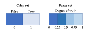
Figure 7: Crisp set and fuzzy set.
4. Simulation
This section shows the design of the control system through the program MATLAB/SIMULINK©2021. For the PI and PID controllers, the controller gains of PI and PID controllers are tuned by using Ziegler–Nichols method as shown in Figures 8 and 9. Where KU = 3.162 and PU = 0.384 s. The gain controller (KP, KI, and KD) is shown in Table 3.
To design a fuzzy logic controller for longitudinal stability control of fixed-wing UAVs, able to design a control system through the program MATLAB/SIMULINK©2021, as shown in Figure 10.
From the structure of the fuzzy logic control system, as shown in Figure 10, it can be seen that there are two input signals for the fuzzy logic controller, the error signal (e) is the difference between the actual measurement pitch angle (output) is compared to the desired pitch angle. The error rate (∆e) is the error change rate over time. The fuzzy logic controller provides an output signal that can be used to control the transfer function of the pitch angle.
To design a fuzzy logic controller, the data value must be changed to a fuzzy set when receiving an incoming signal (crisp input signal) as a number or in the original set format. It uses the semantic characteristics of linguistic variables, which are linguistic variables for the input signal (error and error rate). The output signal is {NB, NM, NS, ZO, PS, PM, PB}, which means a fuzzy set. They have the following meanings: Negative Big, Negative Medium, Negative Small, Zero, Positive Small, Positive Medium, and Positive Big, respectively.
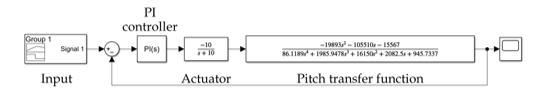
Figure 8: The PI control system.
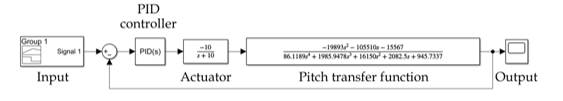
Figure 9: The PID control system.
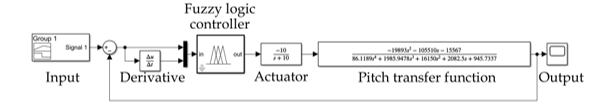
Figure 10. Fuzzy logic control system.
Table 3: The Ziegler–Nichols tuning PI and PID controller method uses Ultimate gain (KU) and Oscillation period (PU).
| Controller | |||
| Proportional-integral (PI) | 1.423 | 4.447 | – |
| Proportional- integral- derivative (PID) | 1.892 | 9.881 | 0.091 |
This research uses two types of membership functions for fuzzy sets: The triangular membership function for {NM, NS, ZO, PS, PM} and the trapezoidal membership function for {NB, PB} are shown in Figure 11 – 13.
The fuzzy rule base provides an output signal for the system’s control. The fuzzy rule base is set according to the “If-Then” rule. The fuzzy rule base has 49 rules, as shown in Table 4.
Figure 14 shows the architecture of a Fuzzy-PID controller. This sort of controller combines a fuzzy logic controller with a PID controller employing an adaptive controller to select the best appropriate controller gains. Figure 15-16 illustrates the membership function employed by the Fuzzy-PID controller, whilst Table 5-7 displays the fuzzy rule base.
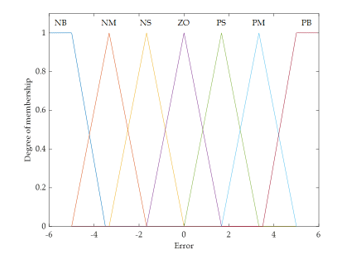
Figure 11. Membership function of error.
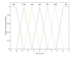
Figure 12. Membership function of error rate.

Figure 13. Membership function of output.
Table 4: Fuzzy logic rules base for fuzzy logic controller.
| Error rate
Error |
NB | NM | NS | ZO | PS | PM | PB |
| NB | NB | NB | NB | NB | NB | NB | NM |
| NM | NB | NB | NB | NB | NB | NM | NS |
| NS | NB | NB | NB | NB | NM | NS | NS |
| ZO | NM | NS | NS | ZO | ZO | PS | PM |
| PS | PS | PS | PM | PB | PB | PB | PB |
| PM | PS | PM | PB | PB | PB | PB | PB |
| PB | PM | PB | PB | PB | PB | PB | PB |
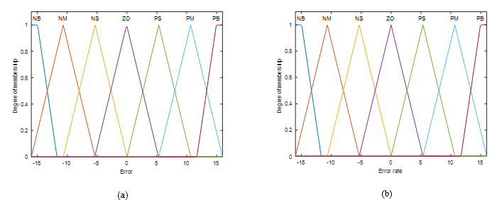
Figure 15. Membership function of input for Fuzzy-PID controller (a) Error (b) Error rate.
Table 5. Fuzzy logic rules base for KP.
| Error rate
Error |
NB | NM | NS | ZO | PS | PM | PB |
| NB | PB | PB | PM | PM | PS | ZO | ZO |
| NM | PB | PB | PM | PS | PS | ZO | NS |
| NS | PM | PM | PM | PS | ZO | NS | NS |
| ZO | PM | PM | PS | ZO | NS | NM | NM |
| PS | PS | PS | ZO | NS | NS | NM | NM |
| PM | PS | ZO | NS | NM | NM | NM | NB |
| PB | ZO | ZO | NM | NM | NM | NB | NB |
Table 6. Fuzzy logic rules base for KI.
| Error rate
Error |
NB | NM | NS | ZO | PS | PM | PB |
| NB | PB | PB | PM | PM | PS | ZO | ZO |
| NM | PB | PB | PM | PS | PS | ZO | NS |
| NS | PM | PM | PM | PS | ZO | NS | NS |
| ZO | PM | PM | PS | ZO | NS | NM | NM |
| PS | PS | PS | ZO | NS | NS | NM | NM |
| PM | PS | ZO | NS | NM | NM | NM | NB |
| PB | ZO | ZO | NM | NM | NM | NB | NB |
Table 7. Fuzzy logic rules base for KD.
| Error rate
Error |
NB | NM | NS | ZO | PS | PM | PB |
| NB | PB | PB | PM | PM | PS | ZO | ZO |
| NM | PB | PB | PM | PS | PS | ZO | NS |
| NS | PM | PM | PM | PS | ZO | NS | NS |
| ZO | PM | PM | PS | ZO | NS | NM | NM |
| PS | PS | PS | ZO | NS | NS | NM | NM |
| PM | PS | ZO | NS | NM | NM | NM | NB |
| PB | ZO | ZO | NM | NM | NM | NB | NB |
5. Results and Discussion
This section shows the simulation results of the designed control system for the pitch control system of the Cessna182 fixed-wing UAV through MATLAB/SIMULINK©2021. The results show the comparison of the response of the original system (no controller), PI controller, PID controller, and fuzzy logic controller.
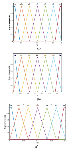
Figure 16. Membership function of output for Fuzzy-PID controller (a) KP (b) KI (c) KD.
For the original system (no controller), it was found that the system had zero position for open-loop transfer function at – 0.1519 and – 5.152 and pole position at -0.0618 0.2359i, – 10 and -11.4685 7.2878i, as shown in Figure 17. For the pole at position -11.4685 7.2878i, the system has a high overshoot and takes a long time to reach equilibrium (settling time).
Therefore, to improve the system’s behaviour, reduce the oscillation (overshoot), and increase the stability of the pitch system. The control system (PI controller, PID controller, and fuzzy logic controller) was designed and simulated through MATLAB/SIMULINK©2021, with the following input format that can be divided into 3 cases.
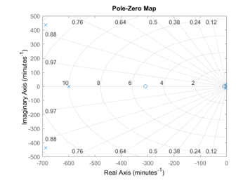
Figure 17: Pole and zero of system.
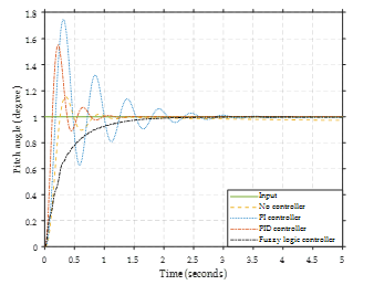
Figure 18: Input as a step up.
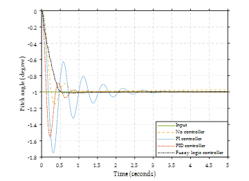
Figure 19: Input as a step-down.
Figure 18 shows the response of step-up input. The noncontroller system is slow to respond and significantly overshoots with high errors. When the PI controller controls the system, the system has a faster response but a high overshoot. The PID controller provides a quick response and lower overshoot than the PI controller. Comparing these results with the fuzzy logic controller shows that the reaction does not have an overshoot.
Figure 19 shows that the system response with step-down input has the same response as a system with step-up input. Systems with no controller have slow response and overshoot. The PI and PID controller systems have a faster response but also a high overshoot. The fuzzy logic controller provides the best response without overshoot and fast system response.
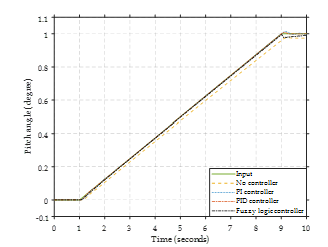
Figure 20: Input as ramp up.
Figure 20 illustrates the response of the system to a ramp-up input. Without a controller, the system malfunctions. The system’s response demonstrates that both PI and PID controllers result in overshoot. Nonetheless, the fuzzy logic controller responds adequately to the desired input without overshooting.
For the ramp-down input, the response is shown in Figure 21 The system response result clearly indicates that the system has an error when there is no controller system. The PI and PID controllers decrease the system’s error but have high overshoot. The fuzzy logic controller provides a satisfactory response with reduced error and overshoot.
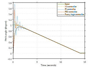
Figure 21. Input as ramp down.
In the second case, the input is a combined disturbance divided into three modes. The response in the second case is shown in Figure 22 – 26.
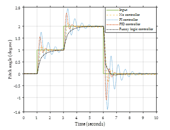
Figure 22. Input mode 1.
The first mode’s response is shown in Figure 22. The system response shows indicates system without a controller has errors and overshoots. PI controllers provide high system response with high overshoot compared to PID controllers and fuzzy logic controllers. The fuzzy logic controller provides a system response that is fault-free and overshoot-free, meaning the system has no oscillation.
For the second mode (Figure 23), this input combines the step input and the ramp input. The system response is as close as possible to the input. From the system’s response, it was found that no controller system has the most valuable error. Fuzzy logic controllers provide the best system response compared to PI and PID controllers.
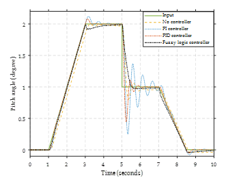
Figure 23. Input mode 2.
The input is a sine wave in the third mode (Figure 24). From the system’s response, it was found that no controller system has the most valuable error. The PID and Fuzzy logic controllers provide the best system response and are as close as possible to the input.
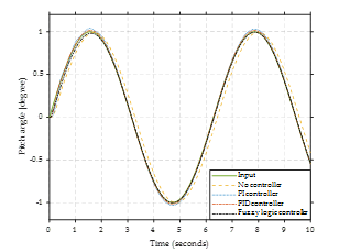
Figure 24. Input mode 3.
For the third case, set the system input as a continuous disturbance, as shown in Figure 25, and zoom-in of input as a constant disturbance shown in Figure 26. From the system’s response, the no-controller system has a high error. PI and PID controllers, a high overshoot is provided. The fuzzy logic controller provides the most input-compliant system response. The system response was no error and overshoot.
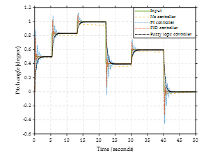
Figure 25. Input as a continuous disturbance.
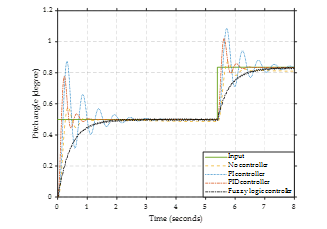
Figure 26. Zoom-in of input as a continuous disturbance.
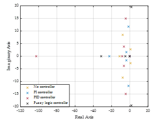
Figure 27. Pole displacement of input as a continuous disturbance.
Figures 27 show the pole displacement of each input mode. The pole displacement of each input mode is the same position because each input mode uses the same controller gains and rules (no controller, PI controller, PID controller, and fuzzy logic controller). Therefore, pole displacements are the same. From the pole position of no control system, PI control systems and PID control systems have pole displacement on imaginary axes that show the system has overshoot or oscillation in the system. For fuzzy logic control systems, make the system not have a pole on an imaginary axis. The system has a fuzzy logic control system without overshoot or oscillation.
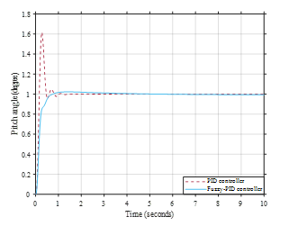
Figure 28. Response of PID and Fuzzy-PID controller.
Figure 28 compares the PID controller’s response to that of the fuzzy PID controller. The control results show that a controller with the application of a fuzzy logic controller has a better system response than a system using a PID controller. As observed from the control effect, when using a controller with the application of a fuzzy logic controller, the overshoot and rise time can be reduced. The steady-state errors are removed.
6. Conclusion
UAVs tend to lose stability easily when they are disturbed by disturbances (Weather or wind gusts). This can cause the UAV to lose control and possibly stall easily. Therefore, UAV systems need a controller that is used to control the stability of the UAV. The longitudinal stability is the most important in many types of stability of UAVs due to the longitudinal stability directly influencing the pitch motion of the UAVs. The pitch motion directly involves UAVs’ take-off, landing, and holding altitude. In this research, the design and simulation of longitudinal stability control of a fixed-wing unmanned aerial vehicle with a feedback controller include PI controller, PID controller, and fuzzy logic controller. The simulation uses MATLAB/SIMULINK©2021 to design the control system with each controller and compare the response of each controller. The controller’s response according to the input format shows the ability to control system behavior. The comparison of the PI, PID, and fuzzy logic controllers show the fuzzy logic controller was able to control the system response as desired or according to the behavior of the input to the system. In the future, in addition to longitudinal stability control, fuzzy logic controllers can also be applied to control other systems in UAVs.
Conflict of Interest
The authors declare no conflict of interest.
Acknowledgment
This research was made possible by the Suranaree University of Technology (Grant Number FF7-707-66-12-82), Thailand Science Research and Innovation (TSRI), and National Science Research and Innovation Fund (NSRF) (NRIIS number 179358).
- H. Shakhatreh, A.H. Sawalmeh, A. Al-Fuqaha, Z. Dou, E. Almaita, I. Khalil, N.S. Othman, A. Khreishah, M. Guizani, Unmanned Aerial Vehicles (UAVs): A Survey on Civil Applications and Key Research Challenges, IEEE Access, 7, 48572–48634, 2019, doi:10.1109/ACCESS.2019.2909530.
- Y. Cheng, S. Xu, Z. Huang, B. Xiong, C. Wang, “Stability control of small fixed-wing UAV,” in Proceeding of the 11th World Congress on Intelligent Control and Automation, IEEE: 1056–1060, 2014.
- V. Phunpeng, T. Kerdphol, “Integrated Piezoelectric and Flexible Solar Systems for Enhancing Inflight Operation Time of Small UAV,” Suranaree Journal of Science and Technology, In press, 1–25, 2022.
- M.-C. Wen, C.-H. Yang, E.-X. Sung, T.-H.R. Wu, Optimized integration of UVAs surveys, and image-based modeling strategies for digital terrain model reconstruction Program of Smart Living View project, 2014.
- J.L. Hernandez, I. González-Hernández, R. Lozano, “Attitude and altitude control for a fixed wing UAV applied to photogrammetry,” in 2019 International Conference on Unmanned Aircraft Systems (ICUAS), IEEE: 498–502, 2019.
- J.H. Yang, H.K. Xu, “Robust Controller Design for Non-Minimum Phase UAV System and System Analysis,” IEEE Access, 6, 70734–70769, 2018, doi:10.1109/ACCESS.2018.2879649.
- B.M. Albaker, M. Majidi, B.M. Albaker, N.A. Rahim, “Flight path PID controller for propeller-driven fixed-wing unmanned aerial vehicles Related papers Flight Cont rol Syst em for Small High-Performance UAVs EXPERIMENTAL FRAMEWORK FOR EVALUAT ION OF GUIDANCE AND CONT ROL ALGORIT HMS FOR UAVs Flight path PID controller for propeller-driven fixed-wing unmanned aerial vehicles,” International Journal of the Physical Sciences, 6(8), 1947–1964, 2011, doi:10.5897/IJPS11.162.
- J. Yang, X. Wang, S. Baldi, S. Singh, S. Fari, “A software-in-the-loop implementation of adaptive formation control for fixed-wing UAVs,” IEEE/CAA Journal of Automatica Sinica, 6(5), 1230–1239, 2019, doi:10.1109/JAS.2019.1911702.
- J. Herkert, J. Borenstein, K. Miller, “The Boeing 737 MAX: Lessons for Engineering Ethics,” Science and Engineering Ethics, 26(6), 2957–2974, 2020, doi:10.1007/s11948-020-00252-y.
- S. Makó, M. Pilát, P. Šváb, J. Kozuba, M. Čičváková, “Evaluation of MCAS System,” Acta Avionica Journal, 2020, doi:10.35116/aa.2020.0003.
- Z. Zheng, Z. Jin, L. Sun, M. Zhu, “Adaptive Sliding Mode Relative Motion Control for Autonomous Carrier Landing of Fixed-Wing Unmanned Aerial Vehicles,” IEEE Access, 5, 5556–5565, 2017, doi:10.1109/ACCESS.2017.2671440.
- E. Ebeid, M. Skriver, J. Jin, “A Survey on Open-Source Flight Control Platforms of Unmanned Aerial Vehicle,” in Proceedings – 20th Euromicro Conference on Digital System Design, DSD 2017, Institute of Electrical and Electronics Engineers Inc.: 396–402, 2017, doi:10.1109/DSD.2017.30.
- M.J. Patyra, J.L. Grantner, K. Koster, Digital Fuzzy Logic Controller: Design and, 1996.
- Electrical4U, “What is a Control System? (Open Loop & Closed Loop Control Systems Explained),” Https://Www.Electrical4u.Com/, 2020.
- M. Saoudi, A. El-Sayed, H. Metwally, “Design and implementation of closed-loop control system for buck converter using different techniques,” IEEE Aerospace and Electronic Systems Magazine, 32(3), 2017, doi:10.1109/MAES.2017.150261.
- V. Jain, “Types of Controllers | Proportional Integral and Derivative Controllers | Electrical4U,” Https://Www.Electrical4u.Com/, 2021.
- V.V. Patel, “Ziegler-Nichols Tuning Method,” Resonance, 25(10), 2020, doi:10.1007/s12045-020-1058-z.
- V.V. Patel, “Ziegler-Nichols Tuning Method: Understanding the PID Controller,” Resonance, 25(10), 2020, doi:10.1007/s12045-020-1058-z.
- V. Kumar, A. Patra, “Application of Ziegler-Nichols Method for tuning of PID controller,” International Journal of Electrical and Electronics Engineers, 8(2), 2016.
- M.J. Patyra, J.L. Grantner, K. Koster, “Digital fuzzy logic controller: Design and implementation,” IEEE Transactions on Fuzzy Systems, 4(4), 1996, doi:10.1109/91.544304.
- C. Elmas, O. Deperlioglu, H.H. Sayan, “Adaptive fuzzy logic controller for DC-DC converters,” Expert Systems with Applications, 36(2 PART 1), 2009, doi:10.1016/j.eswa.2007.11.029.
- J. Carvajal, G. Chen, H. Ogmen, “Fuzzy PID controller: Design, performance evaluation, and stability analysis,” Information Sciences, 123(3), 2000, doi:10.1016/S0020-0255(99)00127-9.
- A.A. Thorat, S. Yadav, S.S. Patil, “Implementation of Fuzzy Logic System for DC Motor Speed Control using Microcontroller,” Journal of Engineering Research and Applications (IJERA), 3(2), 2013.
- A.C. Soh, E.A. Alwi, R.Z.A. Rahman, L.H. Fey, “Effect of Fuzzy Logic Controller Implementation on a Digitally Controlled Robot Movement,” Kathmandu University Journal of Science, Engineering and Technology, 4(1), 1970, doi:10.3126/kuset.v4i1.2881.
- B. Hamed, M. Almobaied, “Fuzzy PID Controllers Using FPGA Technique for Real Time DC Motor Speed Control,” Intelligent Control and Automation, 02(03), 2011, doi:10.4236/ica.2011.23028.
- V. Phunpeng, S. Khaengkarn, T. Hengmeechai, T. Kerdphol, “Longitudinal Stability Assessment of Fixed-Wing UAV based on Fuzzy Closed-Loop Control,” in Proceeding – 2023 International Electrical Engineering Congress, iEECON 2023, 2023, doi:10.1109/iEECON56657.2023.10126642.