Augmented Reality Based Visual Programming of Robot Training for Educational Demonstration Site

Adv. Sci. Technol. Eng. Syst. J. 8(5), 8–16 (2023);
 DOI: 10.25046/aj080502
The human resource development of robotics and automation in the smart factory is an important factor in “Thailand 4.0” roadmap, which is following the industry 4.0 model. To pursue this goal of Thailand 4.0 roadmap of labor development, the effective and intuitive training system must be easy to understand. This study proposes the implementation of augmented reality (AR) technology for training purposes due to its ability to visualize real-time invisible data, such as device status. This involves the development of the AR-based visual programming interface with an educational demonstration site (demo site). The AR-based training system is started with animation content explaining the smart factory concept, followed by hands-on learning using Microsoft HoloLens 2 and IoT hardware devices in demo site. The demo site using an MQTT protocol, simulates an automated packing line in the smart factory. The hardware status is published in real-time to the MQTT broker. This approach enables users to comprehend the interconnected relationship between data and hardware functionality and allowing them to create their own programs to control the IoT hardware in the demo site. With this training, 22 targeted users have successfully grasped the smart factory concept and its correlation with hardware functionality. The block-based visual programming employed in the system enables easy comprehension of robot commands. Moreover, the AR application provides a smooth display at 48-60 frames per second. The proposed system’s usability and value for specific tasks received high scores, ranging from 4 to 5 points, confirming its effectiveness for the targeted users. The proposed AR-based training system has proved that it has benefit for human resource development in the robotics and automation sector following the Thailand 4.0 roadmap. The proposed system empowered users to understand the smart factory concept and its practical implementation, leading to create new ideas for integrating AR and smart factory concepts into their manufacturing in the future.
1. Introduction
The industry 4.0 is the era of using the cyber-physical system [1]-[2] to manage data in manufacturing, which could be called as the smart factory. By transforming production into a digital process and connecting factories to the internet, industry 4.0 can enhance manufacturing performance. Germany is the first nation that mentions about the Industrie 4.0. The German government announces as the national strategic initiative [3] and establishes the platform for industry development to 4.0 and the criteria for evaluating the potential of the factory’s deve lopment. The United State of America (USA) has an important strategy called the Smart Manufacturing. The strategy aims to manage the investments in manufacturing. The National Institute of Standards and Technology (NIST) of USA supports about implementing the robotics in manufacturing and creates the tests for evaluating potential of the automation in the production line. The quality control is the key to modern factory [4]. In Southeast Asia, Singapore prepares the Smart Industry Readiness Index (SIRI) for measuring industrial development readiness. The method emphasizes three dimensions are the process, the technology, and the organization. SIRI shares the framework for developing the industry to industry 4.0.
In Thailand, there is a model for developing the industry called Thailand 4.0.The model aims to help small and medium-sized enterprises (SMEs) become high-potential enterprises. Thailand 4.0 aims to implement the robotics and automation in the production line and labor skill improvement [5]. The Thailand 4.0 strategy identifies five new S-Curve industries: robotics, aviation and logistics, digital, biofuels and biochemicals, and medical hub. [6]. Labors need to improve their skills to support these industries. 70% of factories in Thailand are in 2.0-3.0 stage of industry [7]. The labors and entrepreneurs should prepare for the digital disruption and industry 4.0. These five new targeted industries need high-potential workers and the experts to drive them forward.
Although training in the industry is popular, there are few courses that offer hands-on workshops with hardware or demonstration sites. However, the industrial training system can benefit from the implementation of augmented reality (AR) technology. An AR-based application provides the visualization of data from real IoT equipment installed in an educational demonstration site (demo site). The demo site simulates the working of an automated packing line, demonstrating how the smart components work such as robot arm for pick-and-place jobs or sensors for detecting palettes. Furthermore, the AR-based application of the proposed system provides a visual block-based programming panel that supports beginner user in creating their own programs. The proposed solution, which combines the AR technology and the demo site, aims to increase worker’s understands of the fundamentals of the smart factory concept and improve their robotics and automation skills.
2. Related Works
2.1. Comparison of AR, VR, and MR concepts
In the present, the augmented reality, virtual reality, and mixed reality are implemented in real life with various purposes, such as medical training application, assembly assistance task, augmented reality with data visualization in production line [8] and using these technologies for training system.
The experts explain the concept of augmented reality (AR) as a merging of 3D graphics with the real world [9]. There are three parts of AR-based system which are user, digital world, and real world. User can control the device in real world by interacting with augmented graphics appearing in the head-mount display device such as Microsoft HoloLens.
Virtual reality (VR) is created by all 2D or 3D graphic environment. User does not see any parts of real world. 2D or 3D graphic and virtual environments need a specific device to present the contents. User can see the virtual contents by using headset with head tracker and hand controller to interact with these graphics.
There is no specific clear definition for mixed reality (MR) that can explain the differences between MR and AR. However, the continuum of the popular source defines MR as the technology between the fully real world and fully virtual world [10]. In the other words, AR is a type of MR. Both AR and MR have augmented objects attached to the real environment, but MR may have more complex features such as attaching graphic textures with real characters from the real world, which is called Augmented Virtually – AV. The summary characteristics of AR, VR, and MR are shown in Table 1.
The proposed system aims to display status data in real time while hardware in the demo site is working. The user should be able to see the variation of the data while also seeing the real environment. Therefore, augmented reality technology would be more appropriate for this system than virtual reality.
Table 1: AR, VR, MR Characteristics Comparison
| Topic | AR | VR | MR |
| Can see real environment through the device. | ü | û | Only specific area. |
| Environment [11] | Real world | Virtual world | Mixed |
| Can interact with virtual object | ü | ü | ü |
| Can interact with physical object [12] | ü | û | Only specific object. |
2.2. Augmented Reality in Training and Industry
AR is frequently used in daily life, such as in the camera filters of social media applications, image tracking of 2D markers for modern-day advertising, and training systems in the medical field and industry.
Research on augmented reality technology for training has found that AR-based training systems are most commonly used in industry (35%), vocational training (26%), and medical (13%) applications [13]. Another research in training topics using AR or VR technology showed the successful implementation about AR-based training system in maintenance and assembly task [14]. The traditional way to learn the welding process is to practice with real equipment. However, virtual and augmented reality can now be used to create simulation training systems that are more flexible and cost-effective than the traditional methods. A study that compared two groups of students who used VR and AR for training and practical application found that the group that used the simulation training system had lower operating stress and higher levels of focus than the other group. [15].
Furthermore, AR technology is not only for training system, but this technology can also be used for data visualization in CNC machines. The data, which can be inspected in real time by integrating AR technology with digital twins, is helpful for making the best decisions in the future [16].
2.3. Thailand 4.0, Thailand Professional Qualification Institute, and the survey about the smart factory training topics in Thailand.
Thailand is now a developing country. A roadmap to drive Thailand to be a developed country in 2032 is called Thailand 4.0 [17]-[18]. One of the agenda in the roadmap is about labor improvement.
There are 5 new s-curves industries including robotics for industry, aviation and logistics, biofuels and biochemicals, digital, and medical hub. To develop and re-skill labors in industry field requires a necessary skill about robotics and automation for digital transformation and industry 4.0 revolution.
The Thailand Professional Qualification Institute – TPQI creates career-standard certifications for qualified individuals. The robotics and automation standard is under the robotics cluster in Mechatronics standard including 19 professional qualifications, 66 credits. This is a standard for 5 career levels, which are for operator, technician, engineer or staff, manager, system design engineer, and system integrator [19].
A review of training sessions showed that the curriculum emphasizes automation in industry 3.0, but there is not enough information about smart factories. Most training courses did not offer hands-on hardware practice. There are 3 of the 16 topics that contribute to the demo site for students, as shown in Table 2.
Table 2: Survey of Training Topics
| Organization | Area of content | Providing the demo site for hands-on practice |
| Thai-German Dual Education and E-Learning Development Institute | Wireless connection, IoT, Programming | û |
| Database | û | |
| Remote control, Sensor and actuator, Simulation, Programming | û | |
| Product management, Vision system, Robot and automation, Sensor and actuator, Programming | û | |
| Technology Promotion Association (Thailand-Japan) | IoT, Sensor and actuator, Programming | û |
| Thailand Productivity Institute | AR/VR, IoT, Barcode scanner and actuator | û |
| Data, Cyber security | û | |
| Cloud computing | û | |
| Robot and automation | û | |
| Robot and automation, Programming | û | |
| Thai-German Institute (TGI) | Database | û |
| Database, sensor and actuator | û | |
| Database, Wireless connection | ü | |
| AI | ü | |
| Wireless connection, IoT, Programming | ü | |
| Wireless connection, Sensor and actuator | û |
Developing human resources for interpreters and engineers about the smart factory contents is beneficial for the company. This is the opportunity to develop an appropriate training system for this group using new technology and augmented reality to create a new training experience in industry. The benefits of AR technology, such as data visualization and real-world viewing, can help users easily understand the relationship between device operation and data. Additionally, user’s understanding of the smart factory concept can be improved by watching the video animations provided in this proposed system.
3. Proposed System
The Thailand 4.0 roadmap requires human development to support the robotics and automation industry which is one of five new S-curves industries. To achieve this, reskilling and upskilling efforts in robotics, particularly in smart factory operations, are also required.
This proposed system is an AR-based training system for smart factory concept. It implements augmented reality (AR) technology to create an effective and intuitive training system. The system scenario while using the AR-based application of this proposed system is shown in Figure 1.
The contents of this system include three animation videos that cover the basics of smart factory operations and robot arm programming. The AR application includes content about the automation devices used in smart factories. The demonstration site (demo site) of smart factory simulates how the automation devices in a smart factory line work and are controllable. The AR contents will be displayed on the Microsoft HoloLens 2 headset.
3.1. System Scenario
The proposed system provides an AR-based application that displays the augmented UI panels, AR user interface, on the Microsoft HoloLens 2 headset. Users can view these panels above the demo site, and they are divided into two parts: the left panel and the right panel.
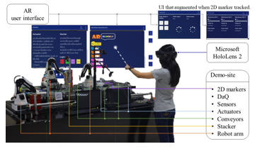
Figure 1: System Scenario
The left panel is the knowledge panel describing the device description, which includes four devices’ contents explaining about the sensors used in the demo site and other popular sensors such as proximity sensors. Secondly, the actuator content provides details about various types of actuators used in the demo site. The third content is a content about conveyor which displays the type of conveyors used in the demonstration site. The final content is the robot arm content, which describes different types of robots and how they work with the demo site. User can switch the contents by clicking the button of each section and control the actuator, the conveyor, and the robot arm by interacting with the buttons that display on each page. The real-time status of each sensor is displayed in the sensor content.
The right panel is for the block-based programming area. Each block is prepared for a specific command, such as controlling robots and conveyors, or if-else logic. To generate a command block, the user needs to click on the desired block displayed on the left side of the panel. The generated block will then appear on the right corner. User needs to drag each command block and snap them together to create an action command. The play button displayed next to this panel is for sending command to the demo site. After the commands are sent, the demo site will execute them step-by-step.
The module’s status panel appeared after the 2D marker is tracked. The status includes the module’s operational status. For the assembly module, the status panel provides information about operating states such as waiting, working, and so on. The status on the warehouse’s panel consists of slot availability. The status of each module is displayed to users in real time.
3.2. System Diagram
Based on Figure 2: System Diagram, the status messages (msg) of each device at the physical level can be transferred to the local broker using the Message Queuing Telemetry Transport (MQTT) protocol. The Node-RED API receives the status and transfers it to the application. When the 2D marker is tracked, the user interface (UI) displays an augmented status panel over the 2D marker.
Once the user finishes programming, the command (cmd) is published from the application. The Node-RED API decodes the command at the API level and distributes it to the devices accordingly. The control of the device is based on the topic that was set earlier.
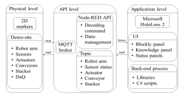
Figure 2: System Diagram
The Physical Level
The physical level consists of five components: MQTT broker, devices, IoT devices, Node-RED execution, and a 2D marker for tracking. The devices and IoT devices implemented in the demo site include robot arms, sensors, actuators, conveyors, stacker, and data acquisition system (DaQ). These physical devices in the real world can be controlled by the user through the application. 2D markers are attached in the demonstration site for providing module information to user when the markers are tracked.
The API Level
There are various libraries used for developing the API level (Application Program Interface), back-end management, and data publication through the broker. The application subscribes to the MQTT topics to receive and send the payload, and a broker publishes a command to that topic for the device to execute at the physical level.
The Application Level
This proposed system was developed using the Unity game engine to create the user interface for the application designed for the Microsoft HoloLens 2. Users can control the demo site by interacting with the user interfaces that appear in the Microsoft HoloLens 2. The user interfaces include the main programming panel (blockly), which provides a block-based programming area, and the knowledge panel, which displays information about the devices.
3.3. Application State Diagram
In Figure 3, the application starts in the initial state and then moves to the connecting state. At this state, the application, the local broker, and the demo site establish a connection. If the connection fails, the Wi-Fi connection in the setting window on the Microsoft HoloLens 2 needs to be checked. Once the connection is successful, the user can interact with the user interfaces displayed on the device to create commands that control the demo site. The application includes a decoding API that converts long commands into step-by-step tasks for the demo site to execute. Finally, the demo site completes the tasks according to the received command.
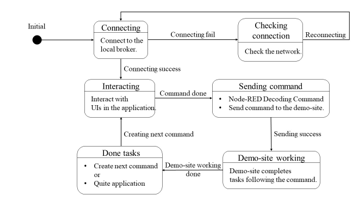
Figure 3: Application State Diagram
3.4. Data Flow
Data flow diagram of the proposed system is shown in Figure 4. There are two parts in the data flow. The first part starts with number 1 and is about the user interface and tracking system. The second part starts with number 2, and includes the MQTT connection and data from the demo site.
Starting at the time before using this system, the application and the demo site need to be connected to the local broker (process 2.0). The connection status shown in the graphic that is augmented on the Microsoft HoloLens 2 display.
The user interface shown on the device is managed by the UI control unit. This unit manages the position of the panels, the position of block command in blockly panel. The snapping function is a part of this unit and is the function for managing the blockly interface. The augmented status panel of the 2D markers developed by using the Vuforia Engine library to define the markers. The UI control unit provides the position of these augmented graphics.
After user publishes their command, the command management system, which includes Node-RED decoding, receives the command and puts it in order. The first command is sent to the demo site and the next command is sent to the demo site after the first command is finished. While the demo site is working, the status data will be updated in real time and shown in the user interface.
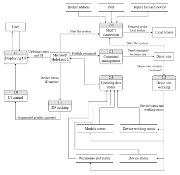
Figure 4: Data Flow Diagram
3.5. Data Synchronization
The device’s status data is published to the MQTT local broker and updated in real time. The information such as sensor status (detected or no detected) or module’s working status (working, waiting, done) is exchanged under the specific topic. The command order is sent after the previous order is completed. Therefore, the device’s working status data and module’s status data must be synchronized between the demo site, API, and the AR application.
3.6. Platforms (Hardware and Software)
Microsoft HoloLens 2
Figure 5 shows the Microsoft HoloLens 2, a head-mounted display for augmented reality applications. The see-through holographic display has a 3:2 aspect ratio and a 2K resolution. It is powered by a Qualcomm Snapdragon 850 computing platform with 4 GB of RAM and 64 GB of storage. It supports WIFI and Bluetooth 5 connections. A single battery charge can last for two to three hours. The device has various sensors including a gyroscope for head tracking, two infrared cameras for eye autofocusing, a 1-megapixel time-of-light depth sensor, light cameras, an accelerometer, a magnetometer, and an 8-megapixel camera for capturing 1080p30 video. It also has built-in spatial sound speakers [20].
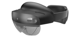
Figure 5: Microsoft HoloLens 2 [21]
Hand gestures can be used to control the Microsoft HoloLens 2. The device can track the index finger and extend a pointer from it towards the augmented object displayed on the screen. To point, the user lifts the left or right hand up and open the palm as shown in Figure 6 (left) and Figure 7 (left). The dash line graphic will appear from the index finger to the target augmented object. The index finger can then be attached to the thumb to drag the graphic to a desired location, or released to click or choose, as shown in Figure 6 (right). Another method for clicking is to push the index finger through the interactive button. The device can detect which graphic is selected, as shown in Figure 7 (right).
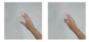
Figure 6: Pointing gesture (left), dragging gesture (right)

Figure 7: Pointing gesture (left), clicking gesture (right)
Microsoft has recommended size for the holographic buttons depends on the distance between user and the target holographic. The shorter distance (45 cm.) uses direct hand interaction which user can use the fingertip to interact the holographic directly. However, this proposed system chooses the hand-ray interaction instead since the ray that augmented on the fingertip is easy to point to the target holographic for the beginner. The target size should be 3.5 x 3.5 cm. for hand ray interaction. The designed distance is around 0.8-1 m. Then, the minimum designed target size of the button is 3.2 x 3.2 cm. Hence, user can interact with the button comfortably.
2D Tracking
The library for 2D tracking system is Vuforia Engine 10.8 which supports the Unity game engine to track the 2D markers using the computer vision based image recognition [22]. This library was developed for AR application [23]. Developers can upload their 2D markers to the Vuforia’s database, with a minimum width of 320 pixels and a maximum size of 2.25 MB for each file [24]. The Vuforia Engine library supports many devices, including the Microsoft HoloLens 2. Once the marker is tracked, the augmented object will appear either above the marker or in a specific position.
Demonstration Site
The demo site prepared for this proposed system is a collaborative project with the educational smart factory platform, which is a research project of the human-computer interface (HCI) laboratory of the Institute of Field Robotics (FIBO), King Mongkut’s University of Technology Thonburi (KMUTT), Thailand.
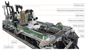
Figure 8: Devices in the Demonstration Site
This demo site simulates the assembly line and operates in separated modules, as shown in Figure 8. The proposed system focuses on the assembly module, the DaQ module consisting of sensors and actuators, and the conveyor module. The hardware includes robot arms, conveyors, sensors, actuators, and input stacker. The communication between the modules in the demo site utilizes the MQTT protocol.
3.7. AR-based Training System
The main contribution of this proposed system is to develop an AR-based application for smart factory concept training system. The system consists of two parts: an AR application including the API, and the contents of smart factory concept.
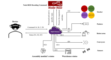
Figure 9: MQTT Data Flow Diagram
Communication between the AR application and devices.
The MQTT protocol is utilized for communication between the AR application and the hardware of the demo site. MQTT broker is configured as the local broker. The scenario of the communication is shown in Figure 9. Each device has its own topics for receiving commands (S1, S2, S3) and updating their operational status (A, B, C, D).
The node-red decoding commands manage the received commands and send them in the correct order to devices, such as stackers, pushers, robot arms, conveyors, and sensors. All statuses from the ended devices will be published to the broker and displayed on the augmented status panels in the Microsoft HoloLens 2.
Node-RED Decoding Command
Node-RED is an online service block-based programming tool [25]. It can create an API for devices and online service using MQTT protocol.
The main API for managing and sending commands to devices in the correct order is the node-red decoding command. The flow chart diagram is shown in Figure 10. The purple block stands for the communication using MQTT protocol.
Starting with the initial state, the sensor and actuator in the palette module will be started. The command (cmd) from the application is sent to MQTT broker in form of string. After the node-red decoding command gets this payload, it will decode command string to command list. The first command set on the index 0 (cmd[0]) of the list will be sent to the device.
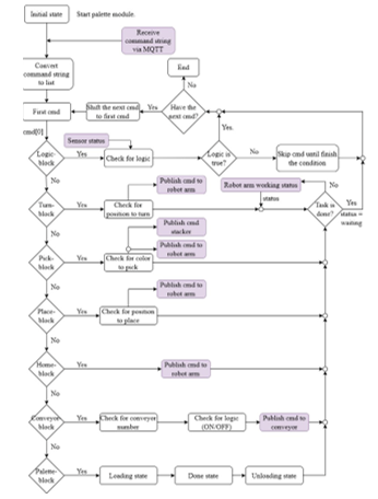
Figure 10: Node-red Decoding Command Flow Chart
The commands such as turning, picking, placing, and homing are related to the robot arm’s operations. The working status of the robot needs to be recognized in real time to prevent the mis-order tasks. The conveyor block controls whether the specific conveyor is on or off.
The logic block will check the sensor status and the logic that the user has previously identified such as the status of object detection. If the condition is true, the demo site will proceed to the next task under this condition scope. If the logic is false, the Node-RED decoding command will skip the tasks under this condition scope and proceed to the next tasks outside of this condition scope.
The user interface in this application consists of two panels as shown in Figure 11. The left panel displays the knowledge contents, while the right panel is the block-based programming area. Both panels are overlaid on the demo site, allowing the user to view them and the environment simultaneously.
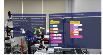
Figure 11: User interface Displayed over the Demo Site(User’s View).
Contents
Three video animations and four device contents are provided for the content about the smart factory concept. The videos cover key areas such as the relationship and differences between industry 4.0 and smart factories, the benefits of upgrading traditional manufacturing to a smart one, the cyber-physical system with the Internet of Things (IoT), and the Industrial Internet of Things (IIoT). They also introduce the basic phase of the programming structure for controlling the robot arm and provide the basic instructions for the robot arm’s three kinds of movements, which are linear, joint, and circular. Additionally, the video animation also presents the professional standards for robotics and automation careers in Thailand, as defined by the Thailand Professional Qualification Institute (TPQI).
The AR application features four device contents that introduces the devices implemented in the demo site. Furthermore, the information about each device helps the users understand the other categories of devices that are frequently used in the smart manufacturing. The device contents are the sensor content, the actuator content, the conveyor content, and the robot arm content.
The real time sensor status is displayed in the sensor content panel. The actuator content panel provides examples of actuator types and easy control buttons that users can use hand gestures to interact with them. In general, the actuators are controlled by electricity or the pressure, such as pneumatic actuators. The buttons can control the input stacker and pusher actuators to push and pull the objects. The elements in the conveyor content panel and the robot arm content panel are similar to those in the actuator content panel. There are the knowledge contents displaying text and the buttons that can control the devices.
Examination and Feedback Forms
This application was evaluated using the pre-test, post-test, system satisfaction feedback forms, and content satisfaction feedback form.
The closed-ended questions in system satisfaction feedback form and the content satisfaction feedback form use the Likert’s scale [26] to measure user’s attitudes. The scale starts from 1 to 5 points where the minimum point stands for strongly disagree / very poor / definitely not, and the maximum point stands for strongly agree / excellent / definitely.
The ideas to develop the factory are collected from the open-ended questions. These questions include how to implement the knowledge gained from the training system in the user’s factory, ideas of implementing the AR technology to their factory, and the suggestions for improving the system.
4. Experimental Results
4.1. Population and Requirement
The proposed system is developed for workers who need to reskill or upskill their performance about robotics and automation in smart factory. The requirements for volunteers include: 1. Working in the automotive or electrical industry. 2. Being a key person in developing their factory into a smart factory. 3. Being an engineer, manager, or staff who is interested in robotics in smart factories. There are 22 volunteers who evaluated the proposed system.
4.2. Tools
Pre-test and Post-test
The purpose of the pre-test is to assess the user’s knowledge background. Questions in pre-test are about contents in the smart factory and fundamental of each device used in the demo site.
The post-test’s questions are the same as the ones in the pre-test. User takes the post-test after watching all video contents and the AR-based training system. The expectation of these tests is that user should get more points after attending the training system. Points gained after using the AR-based training system demonstrate that user has more knowledge about the smart factory concept than they did previously.
System Satisfaction Feedback Form
This form includes general questions about user’s background, usability of this training system, and suggestion for improving the system. The usability questions cover the assessment of values for specific task of the proposed system. The writing parts in this form is used to collect user’s ideas about the factory improvement based on experience after attending this training system.
Content Satisfaction Feedback Form
This form is used to collect the feedback about the contents. The content satisfaction also includes questions for evaluating the values for specific task.
4.3. Tasks
Task 1: User Assessment
There are 2 examinations for user assessment. User needed to follow these steps.
- Taking the pre-test to assess the user’s knowledge background.
- After users have completed all the contents and used the application, they must take the post-test to evaluate their knowledge progress.
Task 2: Learning
There are two types of smart factory contents that users need to learn. The first type is three videos about the smart factory concept. The second type is contents about the devices that are mostly used in smart manufacturing. The device contents are provided in the AR application.
Task 3: Using the Application
- This task is about how to use the application in the Microsoft HoloLens 2 by watching a tutorial video of the application. The video provided the suggested hand gestures to interact with the Microsoft HoloLens 2, the block’s name of the Blockly, and how to use the Blockly by dragging and snapping the blocks together.
- User started by learning about the device contents (sensor, actuator, conveyor, robot arm) that appear in the application. They practiced their hand gestures for interacting by pushing interactive buttons in the knowledge panel.
- User created commands to control the demo site using Blockly panel and completed the given task (Algorithm 1).
- After user completed using the application, user needed to take the system satisfaction feedback form and content satisfaction feedback form.
During operation, the user’s view in the Microsoft HoloLens 2 was live streamed to the developer in real time. If user had the problems with the system or the interaction, developer would suggest how to solve them.
User took an hour to hour and half per one test following the steps 1-9. The time they took is up to how fast they can adjust their hand gestures to interact with the user interface, and how to solve the given programming task by themselves.
The risk of using this training system may cause the motion sickness for some people. To relieve the symptom, user needs to take the Microsoft HoloLens 2 off, sit on the chair and get eyes rest for 10-15 minutes. No one in this study had a motion sickness symptom while using this training system.
| Algorithm 1: Making the Condition. | ||||
| Start; | ||||
| Instruction 1; | ||||
| if condition then | ||||
| Instruction 2; | ||||
| Instruction 3; | ||||
| else | ||||
| Instruction 4; | ||||
| Instruction 5; | ||||
| end | ||||
4.4. Results
The frame rate of the proposed system is in the range of 48-60 fps, which can display the augmented graphics clearly and user can interact with those graphics smoothly.
The formula (1) is to calculate the learning rate of all users measured by the percent change of post-test scores and pre-test scores. While “Post” stands for post-test score, and “Pre” stands for pre-test score.
![]()
Table 3: User’s Changed Learning Rate
| Group | Experience | % changes (%) | Amount of users |
| 1 | Had experience about smart factory and had to implement it in their factory before. | 23.42 | 9 |
| 2 | Had knowledge about the smart factory concept but did not implement it before. | 36.37 | 4 |
| 3 | Had no knowledge and experience about the smart factory concept before. | 75.25 | 9 |
The Table 3 showed that the % changes of all users were increased as 23.42% for 9 users, 36.37% for 4 users, and 75.25% for 9 users. The result showed that this proposed system can deliver the knowledge of the smart factory concept to users. The differences of the % changes are because user had some experience about smart factory before using this proposed system. Users in group 1 had less % changes than the other groups but it did not mean that they obtained few knowledge. The users in group 1 have more ideas of implementing new technology such as AR in their manufacturing processes because they can apply their priori knowledge and experience with this proposed AR-based training system.
The evaluations of the usability and values for specific task are based on 5-point Likert’s scale as shown in Table 4. The usability score of the proposed system obtained 4.44 from 5 points, while score of the values for specific task of the system is about 4.23 from 5 points, and the values for specific task related to the contents obtained 4.30 from 5 points. Moreover, all users had more ideas of implementation new technology such as AR and the smart factory concept to their works.
Table 4: 5-point Likert’s Scale.
| Point | Meaning |
| 1 | Strongly disagree |
| 2 | Disagree |
| 3 | Neither agree nor disagree |
| 4 | Agree |
| 5 | Strongly agree |
5. Conclusions and Discussions
Thailand has the direction to increase the manufacturing performance using the implementation of the smart factory. In the smart industry, skills related to robotics and automation are required. Worker skill is the most important factor in the factory development. The AR-based training system for industrial training with the industry 4.0 contents aimed to develop worker’s knowledge and skills. This proposed system covered the foundation contents about the smart factory and devices used in the smart production line. Moreover, the block-based programming panel is provided in the AR application to support users to practice their programming skills. The Microsoft HoloLens 2 device was selected to work with this system. The graphic contents are displayed on the Microsoft HoloLens 2 screen over the real environment. Worker upskilling can be evaluated with the scores of the pre-test and post-test. The points gained after completing the training from the proposed system indicate that the user’s knowledge of smart factories and robotics and automation has increased.
The smart factory contents in this proposed system enhanced the user’s knowledges. The proposed system can display with
48-60 fps. along with 1440 x 936 pixels per eye. Furthermore, the evaluation scores of the values for specific task and usability were in the range of 4-5 points, indicating that users were satisfied with this proposed system.
The experimental results discovered that the user’s learning rate also depends on their priori knowledge and experiences. However, this proposed AR-based training system can delivery knowledge and experience about the smart factory concept and robot visual programming through augmented reality technology. This helps users to be able to utilize the obtained experiential learning for improving their manufacturing process.
Currently, the contents in this proposed system follows the standards in robotics and automation in TPQI standards. In the future, the blockly panel could be improved to increase the UI performance in order to solve the display delay problem. The various contents about the smart factory and digital disruption can be added to the system. This proposed system can be developed for various contents for training in some specific production lines. Moreover, the display of the device’s status in the proposed system can be implemented for the data visualization in the smart production line.
Conflict of Interest
The authors declare no conflict of interest.
Acknowledgment
We would like to acknowledge the funding from PMU-B’s AI for All 1-2 funds, the KMUTT’s fundamental fund for financial supports, and the Human-Computer Interface Lab at the Institute of Field Robotics for providing the infrastructure and hardware implemented in this research.
- The National Electronics and Computer Technology Center (NECTEC), 2019, Cyber-Physical System, https://www.nectec.or.th/research/research-project/nectec-cps.html.
- Z. Suleiman, S. Shaikholla, D. Dikhanbayeva, E. Shehab, A. Turkyilmaz, “Industry 4.0: Clustering of concepts and characteristics,” Cogent Engineering, 9(1), 2022, doi:10.1080/23311916.2022.2034264.
- Germany Industrie 4.0, https://ati.ec.europa.eu/sites/default/files/2020-06/DTM_Industrie%204.0_DE.pdf.
- NIST, Smart Manufacturing | NIST, https://bit.ly/2IJXL4o.
- The Excise Department, Thailand 4.0, https://www.excise.go.th/cs/groups/public/documents/document/dwnt/mjgy/~edisp/uatucm282681.pdf.
- Business Opportunities, https://www.eeco.or.th/en/business-opportunities.
- The Federation of Thai Industries, 2020, Thailand Competetiveness 2016: Tha IMD Perspective, 6, http://www.nfcrbr.or.th/site/attachments/article/81/White%20paper.pdf .
- D. Mourtzis, V. Siatras, V. Zogopoulos, “Augmented reality visualization of production scheduling and monitoring,” Procedia CIRP, 88, 151–156, 2020, doi:10.1016/j.procir.2020.05.027.
- M. Speicher, B.D. Hall, M. Nebeling, “What is Mixed Reality?,” in Proceedings of the 2019 CHI Conference on Human Factors in Computing Systems, ACM, New York, NY, USA: 1–15, 2019, doi:10.1145/3290605.3300767.
- Paul Milgram, Fumio Kishino, “A Taxonomy of Mixed Reality Virtual Displays”, in IEICE Transaction on Information and Systems, Figure 1, 3.
- Reid Manning, 2022, Augmented, Virtual, and Mixed Reality Training Landscape [Online], Available: https://www.spheregen.com/augmented-virtual-and-mixed-reality-employee-training.
- S. Ke, F. Xiang, Z. Zhang, Y. Zuo, “A enhanced interaction framework based on VR, AR and MR in digital twin,” Procedia CIRP, 83, 753–758, 2019, doi:10.1016/j.procir.2019.04.103.
- F.-K. Chiang, X. Shang, L. Qiao, “Augmented reality in vocational training: A systematic review of research and applications,” Computers in Human Behavior, 129, 107125, 2022, doi:10.1016/j.chb.2021.107125.
- N. Gavish, T. Gutiérrez, S. Webel, J. Rodríguez, M. Peveri, U. Bockholt, F. Tecchia, “Evaluating virtual reality and augmented reality training for industrial maintenance and assembly tasks,” Interactive Learning Environments, 23(6), 778–798, 2015, doi:10.1080/10494820.2013.815221.
- F. Torres-Guerrero, L. Neira-Tovar, L. Torres-Treviño, An Introductive Training for Welding Workshop: A Biometric Evaluation Using Virtual Reality Scenes to Improve Practice, 319–331, 2019, doi:10.1007/978-3-030-18715-6_27.
- Z. Zhu, C. Liu, X. Xu, “Visualisation of the Digital Twin data in manufacturing by using Augmented Reality,” Procedia CIRP, 81, 898–903, 2019, doi:10.1016/j.procir.2019.03.223.
- Educational Management, 2559, Thailand 4.0 Blueprint, https://waa.inter.nstda.or.th/stks/pub/2017/20171114-draeqa-blueprint.pdf.
- Office of The Official Information Commission, Thailand 4.0, http://www.oic.go.th/FILEWEB/CABINFOCENTER3/DRAWER049/GENERAL/DATA0000/00000702.PDF.
- Thailand Professional Qualification Database System, Robotics and Automation, https://tpqi-net.tpqi.go.th/home/occ/industrialInfo/RAC.
- Microsoft, HoloLens 2, https://www.microsoft.com/en-us/HoloLens/hardware#OneGDCWeb-Banner-ffqoo6k.
- Mikko Ruotsalainen, Lari Komulainen, Alex Tejada, “Virtual Lenses to Support Study Work at Customer Site”, School of Engineering Science, 2021.
- Vuforia, Getting Started with Vuforia Engine in Unity, https://library.vuforia.com/getting-started/getting-started-vuforia-engine-unity.
- Vuforia, Image Targets, https://library.vuforia.com/objects/image-targets.
- D. Amin, S. Govilkar, “Comparative Study of Augmented Reality Sdk’s,” International Journal on Computational Science & Applications, 5(1), 11–26, 2015, doi:10.5121/ijcsa.2015.5102.
- Node-RED, https://nodered.org.
- I. Elaine Allen and Christopher A. Seaman. (2022). Likert Scales and Data Analyses, https://www.bayviewanalytics.com/reports/asq/likert-scales-and-data-analyses.pdf.