Design and Manufacturing of Soft Grippers for Robotics by Injection Molding Technology

Adv. Sci. Technol. Eng. Syst. J. 8(4), 11–17 (2023);
 DOI: 10.25046/aj080402
Soft robots have softer, more flexible, and more compliant characteristics than traditional rigid robots. These qualities encourage more secure relationships between people and machines. Nevertheless, traditional robots continue to rule the commercial sector. Due to the high cost of gripper production, soft robots are very far from being commercially feasible. This research focuses on fabricating a soft robotic gripper with the potential for mass production using injection molding technology. The material used for manufacture is Thermoplastic Elastomer (TPE). This study gives an injection molding optimization strategy by using Moldex 3D simulation to minimize production time for soft grippers. Furthermore, using an Ansys workbench, this study simulated soft gripper deflections with variable pressures by finite element analysis and then compared it with the actual experiment. The simulation results of TPE warpage volume shrinkage are 11.969% and 11.96% in the molding experiment. Thus, the shrinkage and warpage for the simulation and actual experiment are similar. According to the simulation outcome, the success of TPE hollow injection molding facilitates soft gripper creation. The maximum pressure used in the FEM simulation of the bending experiment was achieved at the pressure of 50 kPa with 152.02 mm of deformation and compared to the experimental data, 145,03 mm. This error is less than 5%. Finally, a better soft gripper design was achieved by Ansys simulation, and the soft gripper appears to be ready for mass-produced by TPE injection molding.
1. Introduction
Robots have typically been made of stiff materials in order to generate accurate, predictable movements with minor deformation. As a result, rigid robots can accomplish activities with great precision and accuracy in controlled environments. However, nature regularly utilizes compliant and flexible structures in unstructured conditions to generate movement and manipulation. Therefore, because of such organic designs, soft robotics is becoming increasingly popular [1–6].
Soft grippers are needed for soft robots to generate motion and force. Soft grippers can develop the flexibility and adaptation necessary to construct extraordinarily adaptive robotics for soft interactions in the absence of an inflexible skeleton in soft robots. Because of its versatility in filling the gap left by typical rigid robots, the soft gripper is gaining popularity. Therefore, one area where soft robotics can have a substantial impact is the development of soft grippers. Soft grippers are one kind of soft robotics that uses softness to provide highly compliant and adjustable grasping capability [7].
The utilization of rigid grippers designed to handle delicate objects is frequently problematic or limited. As one potential solution, a soft device that can passively adjust to the object and its surroundings could replace the gripper’s role. As a result, numerous soft mechanical architectures have been proposed, and extensive research on soft robotics has been conducted [8–10]. Soft robotics, unlike rigid robotics, can adapt to changing environmental conditions and interact with people more securely and flexibly. As a result, soft robot design and fabrication have significantly progressed over the last ten years, and new actuator design and fabrication processes have been created and improved [11,12].
The development of novel materials and soft components is advancing in order to create lighter, simpler general grippers. Compliance has always been considered important in grasping. Shocks induced by contact with a firm gripper and a rigid object, if not adequately regulated, can injure the product or force it outside of the targeted route. Incorporating sensitive materials into robotic end effector grabbing portions is a basic but only partially successful alternative (for example, in the shape of basic rubber pads). Interaction between bodies, on the other hand, impedes their mobility [13–15]. Soft grippers use the responsiveness and elasticity of materials to build highly flexible robotic arms that allow for secure contact between devices and the surrounding. Therefore, when making soft grippers, it is vital to consider the materials and production processes [16–18].
Soft grippers, in contrast to standard robots, are often made from materials with Young’s moduli equivalent to soft biological materials such as muscles, tendons, and skin, typically about 1e-7GPa-1GPa. Compatibility and “softness” are produced using morphology and material characteristics in naturally pliable materials. However, soft materials have limitations regarding potential manufacture, non-linear response, modeling complexity, self-repair, and fatigue performance. Therefore, elastomers and rubbers, which can sustain reversibly (>100%) due to tremendous loads, are the most frequently utilized soft grip materials [16,19]. Thermoplastic elastomers have emerged as the most popular option for industrial applications in this study because of their low toxicity, robustness, and mechanical dampening characteristics and their simplicity of manufacture [20].
However, due to the high cost of gripper production, soft robots are very far from commercially feasible. When it comes to mass production, forming is the most cost-efficient and has the lowest unit cost of the three basic types of manufacturing: forming, machining (subtractive), and additive manufacturing [21].
In addition, the intricacy of the fabrication procedure may result in a more extended fabrication period that may last from hours to days, and the high expense of typical gripper production methods all contribute to this. Therefore, an efficient fabrication process is required to ensure acceptable mechanical performance while reducing fabrication time and complexity.
Thus, this research focuses on fabricating soft robotic grippers that have the potential for mass production. Consequently, this research concentrates on the material used for soft grippers and a unique process for manufacturing soft grippers with high throughput and mass production potential. For this reason, TPE hollow injection molding was chosen because it is a high-speed, automatic technique that can produce parts with a wide range of sizes and extremely complicated geometries in large quantities.
2. Theoretical Background
There are numerous mathematical models for viscosity accessible in Moldex3D. TPE is used in all injection molding simulations in this study. Moldex3D’s suggested viscosity model for this material is the Modified Cross Model 3, often called the Cross-WLF model. In this model, the melt viscosity is dependent on the shear rate , temperature T, and pressure p, according to:
![]()
where (zero-shear rate viscosity), n (power-law index with a value between 0 and 1), (relaxation stress). The viscosity versus shear rate obtained from the Cross Model using the TPE material is depicted in Figure 1 for temperatures of 190°C, 215°C, and 240°C, respectively.
Table 1: Cross-WLF model data for TPE melt viscosity [22]
| n | 0.264907 | – |
| Taus | 153557 | dyne/cm^2 |
| B | 4.30664e-06 | g/(cm.sec) |
| Tb | 10819 | K |
| D | 0 | cm^2/dyne |
The shear-dependent parameters are identical to those in the Modified Cross Model. Correlating low-temperature viscosity with the Cross-WLF model is often more accurate. The Cross-WLF model outperforms the Cross-Exp model at temperatures below Tg+100°C.
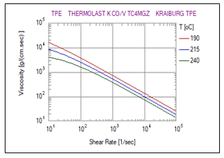
Figure 1: Viscosity versus shear rate for TPE
Modified Tait Model 2, used in this work and offered by Moldex 3D, can be used to explain the PVT model.
![]()
is the specific volume (contrarywise proportional to density) at Temperature, T. Pressure, P, is a specific volume at zero gauge pressure, C is a constant of 0.0894 and accounts for the material pressure sensitivity, as shown in Figure 1. For the upper-temperature region and the lower-temperature region respectively. Figure 2 illustrates the specific volume dependency for TPE on Temperature and pressure.
Table 2: PVT data for TPE [22]
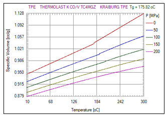
Figure 2: PVT diagram for TPE
Because these are equilibrium states, the PVT characteristics of polymers in the molten state may be appropriately described by the equation of state (EoS).
The generalized Newtonian fluid (GNF) theory predicts that the polymer melt will behave [23,24]. Because the GHS flow model depicts the flow within two plates that are close together, the width of the gap is considered to be substantially slighter than the other flow parameters. This notion concludes that local geometry has the greatest influence on flow at a single spot. Because velocity in the gap-wise orientation is ignored and pressure is simply an expression of planar coordinates, the lubrication approximation may be used. The following equations describe the melt flow of the Hele-Shaw polymer:
Continuity equation:
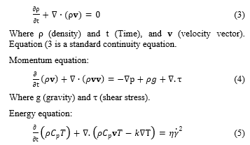
where T (temperature field), Cp (heat capacity), k (thermal conductivity coefficient), (viscosity of the fluid), and (shear rate).
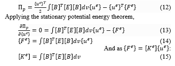
The function used in the elasticity problem is the structure’s total potential energy. In the first step, assume an estimated form for the solution, and the answer should be acceptable and meet the crucial internal compatibility and boundary restrictions. The optimal constant values are then obtained using the stationary potential energy theorem. The theory states that among all acceptable arrangements of a conservative system, the ones that satisfy the equations of equilibrium render the potential energy constant when allowable displacement fluctuations are taken into consideration., i.e., equilibrium configurations are defined when:
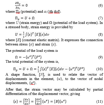
where [B] is the strain-displacement matrix. Substituting (10) into (9),
The soft gripper body in this research is made of a thermoplastic elastomer (TPE), a hyper elastic material. Because the material feature of a hyper elastic material is non-linear under external forces, the strain energy density function is extensively employed to describe the mechanical features of TPE material. In this paper, the Yeoh model proposes a non-linear association between material stress and strain. Yeoh thought that the strain tensor invariants I2 had no effect on the strain energy and might be ignored entirely. Here is the simplified strain energy density function:
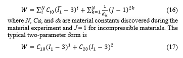
The 2nd Yeoh Parameter hyper-elastic material model was used to model the TPE material and fit its average stress-strain data.

Figure 3: The 2nd Yeoh Stress-Strain Model data of TPE
Table 3: TPE Hyper-Elastic Material Model Constants
| Model for TPE Hyper-Elastic Materials | Constant Material | Value (Pa) |
|
The 2nd Yeoh Parameter |
C10 | 6.6275+05 |
| C20 | -62451 | |
| Incompressibility Parameter D1 | 0 | |
| Incompressibility Parameter D2 | 0 |
3. Design and Experimental of TPE Soft Gripper
3.1 Soft Gripper Design
A soft gripper form was created in this study, as illustrated in Figure 4. The TPE soft grippers’ air chamber is enclosed within the gripper body. Once air pressure is applied and motion is formed, this air chamber enlarges to accomplish bending deformation. The dimension of the TPE soft gripper is 114 x 19 x 16.5 mm [1]. This design has been proven can accomplish pleasant bending deformation by previous studies [25].
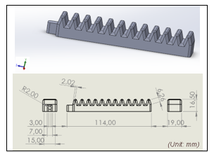
Figure 4: The TPE soft gripper design [1]
3.2 Soft Gripper Mold Design
The soft gripper’s mold design was achieved after designing a soft gripper body, as shown in Figure 5.
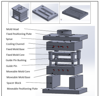
Figure 5: Gripper mold design
3.3 Mold Manufacturing
A High-Speed/Closed-Loop Hybrid Injection Molding Machine produces the soft gripper (AF Series). The soft gripper is meant to be flexible in this experiment, and TPE was employed. Figure 6 depicts the soft gripper mold used to create the soft gripper.
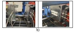
Figure 6: TPE Hollow Gripper a) Mold [1] and b) Injection Molding Machine
3.4 The Simulation of Soft Gripper
Simulations carried out in ANSYS Workbench using a Static Structural Analysis. The finite element diagram in Figure 7 illustrates and describes the processes necessary to model a soft gripper
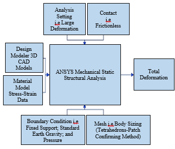
Figure 7: Diagram of finite element simulation
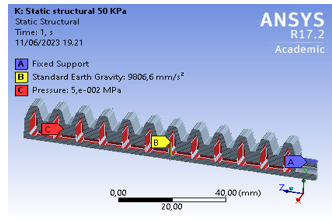
Figure 8: Simulation boundary condition diagram
TPE soft gripper uses tetrahedrons meshed, with the element size adjusted to 1 mm. The whole deformation is caused by pressure given to the TPE soft gripper, exhibiting the gripper is stretched at various phases of the pressure applied. Figure 8 displays a boundary condition simulation of the soft gripper.
Aside from the numerical simulations used (Ansys software), further unique and powerful numerical approaches for strain-stress analysis of isotropic or anisotropic media have recently been developed. The “Gaussian Quadrature” and “Bezier” techniques, among others, demonstrated more stability and accuracy than previous numerical approaches. Alternatively, these approaches may forecast soft gripper deflections with variable pressure [26,27].
3.5 Grasping Experiment
The grasping experiment is applied in this research to examine the condition of the gripping force. Figure 9 depicts the fixture design, which includes the length, pitch between the chambers, and air pressure. As a result, the plastic ball object is grasped well without any defect on the object, as shown in Figure 15.
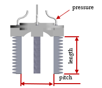
Figure 9: The fixture design: length, pitch, and the air pressure
4. Result and Discussion
4.1 Injection Molding Simulation
Moldex 3D has been used to simulate Injection Molding tests of TPE soft gripper. First, as shown in Table 4, the results were achieved by simulating the injection molding process. Following that, the filling phase simulation is seen in Figure 10.
Table 4: Soft Gripper Injection Molding Simulation
| Parameter | Value |
| Melt Temperature (℃) | 210 |
| Cooling Channel Temperature (℃) | 20 |
| Mold Temperature (℃) | 50 |
| Maximum Injection Pressure (MPa) | 30 |
| Maximum Packing Pressure (MPa) | 20 |
| Cooling Flow Rate ( | 120 |
| Filling Time (sec) | 2 |
| Cooling Time (sec) | 30 |
| Holding Time (sec) | 2 |
| Mold-Open Time (sec) | 5 |
| Eject Temperature (℃) | 70 |
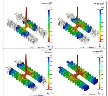
Figure 10: Filling phase simulation of the TPE 40%, 60%, 80%, and 100%
4.2 Soft Gripper Manufacturing
This manufacturing of the soft gripper is displayed in Figure 11. To prevent the TPE material from absorbing moisture and causing pores in the finished product. The material must be dried before being injected into the molding machine. After determining the injection volume, the finished product has shrinkage and slight overflow. Therefore, the mold temperature has to adjust to reduce the mold temperature and increase the packing pressure to prevent the overflow and shrinkage of the finished product. The finished product is displayed below in Figure 11.
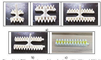
Figure 11: a) Filling experiment of the soft gripper 40%, 60%, and 80%, b) Gripper ejected from the mold after 100% filling, and c) Final gripper after glued
Compared to traditional production, the production time might range from hours to a day. However, most soft gripper manufacturers use 3D printing, which takes 35 minutes [28]. Therefore, the production time of one soft gripper is less than 5 minutes in this work, and we obtained an optimization technique for lowering time and expenses in creating soft grippers.
4.3 Warpage and Shrinkage Comparison
By the result of the total warpage displacement of Moldex 3D simulation and the experiment of the injection molding machine, the final of the simulation and experiment of the soft gripper. According to the result of Moldex 3D, warpage occurs, and the total warpage volumetric shrinkage is 11.969% based on the simulation. The original design size of the soft gripper was 114x19x16.5 mm. However, due to the warpage, the dimension of the soft gripper changed to 103×18.64×16.43 mm. Thus, the warpage volume shrinkage of the actual experiment is 11.96%. Remarkably similar for both simulation and experiment results.
4.4 Bending Comparison
The TPE soft gripper’s bending experiment performs well in the bending pressure experiment, both positive and negative pressure. Furthermore, this design works as expected, considering the bending restriction from the previous research is eliminated as the gripper has no edge touching for the negative bend.
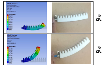
Figure 12: Actual positive bending deformation of soft gripper
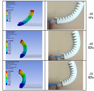
Figure 13: Actual negative bending deformation of soft gripper
However, this product’s weakest sections can also be identified as the areas where fastening processes are used. Thus, processes involving high pressure or heavy loads increase the product’s propensity to failure. Under excessive pressure, it will lead to failure and may cause the material to burst, rip, or deform permanently. Due to the fact that this soft gripper design must be glued after being manufactured, significant air pressure may cause separation between the two sections of the gripper finger as well. Furthermore, the chemicals employed in bonding can potentially harm the environment. Therefore, in this experiment, the range of air pressure applied only between -50 to 50 KPa, as shown in Figures 12 and 13.
Based on the comparison between simulation and actual experiments of bending deformation of the soft gripper with several pressure differences, Figure 14 shows the influence of the pressure.
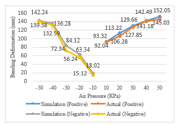
Figure 14: TPE bending deformation comparison influenced by the pressure
4.5 Grasping Experiment
Three soft grippers have been constructed using the fixture design in Figure 9 and utilized to pick up a softball as the goal is to examine the grasping force, as shown in Figure 15. The air pressure applied to the gripper is 40 KPa in order to get enough bending deformation to grasp the object. A 3D print weight object was also attached to the ball to examine the bending strength to encounter the additional weight beside the ball.
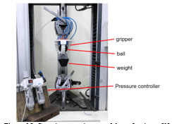
Figure 15: Grasping experiments of the soft gripper [1]
5. Conclusion
The numerical analysis of injection molding was done by Moldex 3D. The soft gripper deformation was successfully predicted by Ansys software, then proved by actual experiment. In both positive and negative pressure conditions, higher air pressure causes more widespread deformation of the soft gripper. Injection molding and FEM simulations indicated that creating a soft gripper is straightforward. Furthermore, the modeling and real outcomes are fairly similar. In Moldex 3D simulation, the value of shrinkage is 11.969%, compared to the experiment of the soft gripper is 11.96%. Thus, the percentage warpage volumetric shrinkage for the simulation and actual experiment is similar. However, for future research, the directions may be to discover other convenient designs or material combinations to fulfill manufacture on a mass scale following the needs of Industry 4.0. It is recommended to use an injection molding machine as the manufacturing method since it is a popular technique for producing plastic components on a massive scale.
Conflict of Interest
The authors declare no conflict of interest.
Acknowledgment
The authors would like to thank the Ministry of Science and Technology (MOST) in Taiwan for the financial support of MOST-107-2221-E-224-045.
- M.R.F. Saduk, H.D. Bryantono, S.C. Tseng, “Engineering Design of Soft Gripper and Manufacturing by TPE Hollow Injection Molding,” in Proceedings – 2022 IET International Conference on Engineering Technologies and Applications, IET-ICETA 2022, Institute of Electrical and Electronics Engineers Inc., 2022, doi:10.1109/IET-ICETA56553.2022.9971524.
- M.R. Fillipin Saduk, H. Jiaqi, S.C. Tseng, “Modeling and Experiments of a Soft Gripper for Robotics Arms Applications,” in Proceedings of the 2022 8th International Conference on Applied System Innovation, ICASI 2022, Institute of Electrical and Electronics Engineers Inc.: 179–182, 2022, doi:10.1109/ICASI55125.2022.9774440.
- C. Majidi, Soft Robotics: A Perspective – Current Trends and Prospects for the Future, Soft Robotics, 1(1), 5–11, 2014, doi:10.1089/soro.2013.0001.
- D. Rus, M.T. Tolley, Design, fabrication and control of soft robots, Nature, 521(7553), 467–475, 2015, doi:10.1038/nature14543.
- D. Trivedi, C.D. Rahn, W.M. Kier, I.D. Walker, “Soft robotics: Biological inspiration, state of the art, and future research,” Applied Bionics and Biomechanics, 5(3), 99–117, 2008, doi:10.1080/11762320802557865.
- S. Kim, C. Laschi, B. Trimmer, Soft robotics: A bioinspired evolution in robotics, Trends in Biotechnology, 31(5), 287–294, 2013, doi:10.1016/j.tibtech.2013.03.002.
- J. Shintake, V. Cacucciolo, D. Floreano, H. Shea, Soft Robotic Grippers, Advanced Materials, 30(29), 2018, doi:10.1002/adma.201707035.
- P. Bharath Vamsi, V. Ragavendra Rao, “Design and fabrication of soft gripper using 3D printer,” in IOP Conference Series: Materials Science and Engineering, Institute of Physics Publishing, 2018, doi:10.1088/1757-899X/402/1/012026.
- T. Hassan, M. Manti, G. Passetti, N. d’Elia, M. Cianchetti, C. Laschi, “Design and development of a bio-inspired, under-actuated soft gripper,” in 2015 37th Annual International Conference of the IEEE Engineering in Medicine and Biology Society (EMBC), IEEE: 3619–3622, 2015.
- R. Maruyama, T. Watanabe, M. Uchida, “Delicate grasping by robotic gripper with incompressible fluid-based deformable fingertips,” in 2013 IEEE/RSJ International Conference on Intelligent Robots and Systems, IEEE: 5469–5474, 2013.
- Y. Yang, Y. Wu, C. Li, X. Yang, W. Chen, “Flexible Actuators for Soft Robotics,” Advanced Intelligent Systems, 2(1), 1900077, 2020, doi:10.1002/aisy.201900077.
- J. Pinskier, D. Howard, “From Bioinspiration to Computer Generation: Developments in Autonomous Soft Robot Design,” Advanced Intelligent Systems, 4(1), 2100086, 2022, doi:10.1002/aisy.202100086.
- M. Kaur, W.S. Kim, “Toward a Smart Compliant Robotic Gripper Equipped with 3D‐Designed Cellular Fingers,” Advanced Intelligent Systems, 1(3), 1900019, 2019, doi:10.1002/aisy.201900019.
- F. Schmitt, O. Piccin, L. Barbé, B. Bayle, Soft robots manufacturing: A review, Frontiers Robotics AI, 5(JUN), 2018, doi:10.3389/frobt.2018.00084.
- Z. Wang, Y. Torigoe, S. Hirai, “A Prestressed Soft Gripper: Design, Modeling, Fabrication, and Tests for Food Handling,” IEEE Robotics and Automation Letters, 2(4), 1909–1916, 2017, doi:10.1109/LRA.2017.2714141.
- J. Hughes, U. Culha, F. Giardina, F. Guenther, A. Rosendo, F. Iida, Soft manipulators and grippers: A review, Frontiers Robotics AI, 3(NOV), 2016, doi:10.3389/frobt.2016.00069.
- S. Zaidi, M. Maselli, C. Laschi, M. Cianchetti, “Actuation Technologies for Soft Robot Grippers and Manipulators: A Review,” Current Robotics Reports, 2(3), 355–369, 2021, doi:10.1007/s43154-021-00054-5.
- G. Alici, “Softer is harder: What differentiates soft robotics from hard robotics?,” in MRS Advances, Materials Research Society: 1557–1568, 2018, doi:10.1557/adv.2018.159.
- L. Wang, F. Iida, “Deformation in Soft-Matter Robotics: A Categorization and Quantitative Characterization,” IEEE Robotics and Automation Magazine, 22(3), 125–139, 2015, doi:10.1109/MRA.2015.2448277.
- Z. Wang, K. Or, S. Hirai, “A dual-mode soft gripper for food packaging,” Robotics and Autonomous Systems, 125, 2020, doi:10.1016/j.robot.2020.103427.
- W. Zhou, J. Lin, D.S. Balint, T.A. Dean, “Clarification of the effect of temperature and strain rate on workpiece deformation behaviour in metal forming processes,” International Journal of Machine Tools and Manufacture, 171, 2021, doi:10.1016/j.ijmachtools.2021.103815.
- M.-L. Wang, R.-Y. Chang, C.-H.D. Hsu, Molding simulation: Theory and practice, Carl Hanser Verlag GmbH Co KG, 2018.
- H. Schlichting, K. Gersten, H. Schlichting, K. Gersten, “Fundamentals of boundary-layer theory,” Boundary-Layer Theory, 29–49, 2000.
- M.R. Barone, C. Tucker, Fundamentals of computer modeling for polymer processing, Hanser, 1989.
- Y. Hao, T. Wang, Z. Ren, Z. Gong, H. Wang, X. Yang, S. Guan, L. Wen, “Modeling and experiments of a soft robotic gripper in amphibious environments,” International Journal of Advanced Robotic Systems, 14(3), 2017, doi:10.1177/1729881417707148.
- S.E. Mousavi, N. Sukumar, “Generalized Gaussian quadrature rules for discontinuities and crack singularities in the extended finite element method,” Computer Methods in Applied Mechanics and Engineering, 199(49–52), 3237–3249, 2010, doi:10.1016/j.cma.2010.06.031.
- H. Kabir, M.M. Aghdam, “A generalized 2D Bézier-based solution for stress analysis of notched epoxy resin plates reinforced with graphene nanoplatelets,” Thin-Walled Structures, 169, 2021, doi:10.1016/j.tws.2021.108484.
- B.N. Peele, T.J. Wallin, H. Zhao, R.F. Shepherd, “3D printing antagonistic systems of artificial muscle using projection stereolithography,” Bioinspiration and Biomimetics, 10(5), 2015, doi:10.1088/1748-3190/10/5/055003.