
Doubling the Number of Connected Devices in Narrow-band Internet of Things while Maintaining System Performance: An STC-based Approach
Volume 8, Issue 4, Page No 01-10, 2023
Author’s Name: Abdulwahid Mohammed1,a), Mohamed S. Elbakry2, Hassan Mostafa3,4, Abdelhady Abdelazim Ammar1
View Affiliations
1Department of Electronics and Communication Engineering, Al-Azhar University, Cairo, 11651, Egypt
2Department of Electronics and Communications Engineering, Institute of Aviation Engineering and Technology, Giza, 25152, Egypt.
3Department of Electronics and Communication Engineering, Cairo University, Giza, 12613, Egypt
4Department of Electronics and Communication Engineering, University of Science and technology, Giza, 12578, Egypt
a)whom correspondence should be addressed. E-mail: awh9140@gmail.com
Adv. Sci. Technol. Eng. Syst. J. 8(4), 01-10 (2023); ![]() DOI: 10.25046/aj080401
DOI: 10.25046/aj080401
Keywords: NB-IoT, 5G, LPWAN, OFDM, STC, STC-OFDM

Export Citations
Narrow-band Internet of Things (NB-IoT) is a low-power wide-area network (LPWAN) method that was first launched by the 3rd generation partnership project (3GPP) Rel-13 with the purpose of enabling low-cost, low-power, and wide-area cellular connections for the Internet of Things (IoT). As the demand for over-the-air services grows and with the number of linked wireless devices reaching 100 billion, wireless spectrum is becoming scarce, necessitating creative techniques that can increase the number of connected devices within a restricted spectral resource to satisfy service needs. Consequently, it is vital that academics develop efficient solutions to fulfill the quality of service (QoS) criteria of the NB-IoT in the context of 5th generation (5G). This study paves the way for 5G networks and beyond to have increased capacity and data rates for NB-IoT. Whereas, this article suggests a method for increasing the number of connected devices by using a technique known as symbol time compression (STC). The suggested method reduces the occupied bandwidth of each device without increasing complexity, losing data throughput, or affecting bit error rate (BER) performance. The STC approach is proposed in the literature to work with conventional orthogonal frequency-division multiplexing (OFDM) to reduce bandwidth usage by 50% and enhance the peak-to-average power ratio (PAPR). Specifically, an STC-based technique is suggested that exploits the available bandwidth to increase the number of linked devices by double while keeping the complexity and performance of the system. Furthermore, the µ-law companding technique is leveraged to reduce the PAPR of the transmitted signals. The obtained simulation results indicate that the suggested method using the µ-law companding technique doubles the amount of transferred data and lowers the PAPR by 3.22 dB while keeping the same complexity and BER.
Received: 18 January 2023, Accepted: 01 July 2023, Published Online: 21 July 2023
1. Introduction
The IoT has changed dramatically in recent years. In particular, the number of IoT devices is rapidly expanding, and various novel IoT applications relating to automobiles, transportation, the power grid, agriculture, metering, and other areas have emerged. According to the Forbes analysis 2017, the worldwide IoT industry will be worth $457 billion by 2020 [1]. However, this amount was already surpassed in 2019 with a worldwide market size of $465 billion (Transforma Insights, 2020) [2]. According to the recent study provided by [2], there were 7.6 billion active IoT devices at the end of 11% compound annual growth rate (CAGR), as shown in Figure 1.
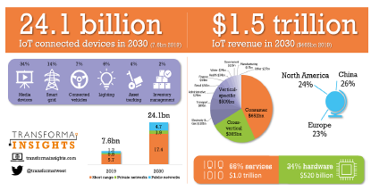
Figure 1: The IOT market 2019-2030 (Transforma Insights, 2020) [2].
Several low-power wide area (LPWA) technologies have been developed to meet this enormous demand for data with the goals of increasing network coverage, enhancing power consumption, supporting more users, and reducing device complexity. Different standard-development organizations, including IEEE and 3GPP, work to standardize LPWA technologies. Both cellular and noncellular wireless technology can be used in LPWA. Machine Type Communication (MTC), Improved Machine Type Communication
(eMTC), and Narrowband Internet of Things (NB-IoT) are examples of cellular technologies, while non-cellular technologies include Long Range (LoRa), ZigBee, Bluetooth, Z-Wave, and others[3]. With the fast development of 5G new radio technologies, intensive research on enhanced mobile broadband (eMBB), massive machinetype communications (mMTCs), and ultrareliable low latency communications (URLLCs) have gotten a lot of interest from academics and industry [4]. To satisfy the 5G outlook, it is necessary not only to achieve significant improvements in new wireless technologies but also to take into account the harmonious and fair coexistence of heterogeneous networks and compatibility between 4G and 5G systems [5]. As shown in Figure 2, the unprecedented growth of the IoT creates an enormous demand for MTC, which can be divided into three categories: 1) short-distance MTC (distance = 10 m), 2) medium-distance MTC (distance ranges between [10 m, 100 m]), and 3) long-distance MTC (distance ≥ 100 m).
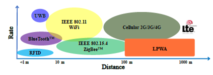
Figure 2: Coverage and transmission rate comparisons of wireless systems [6].
2. Literature Review and Contribution
The maximum likelihood of cross-correlation detection is presented by the authors in [7] as a hardware implementation. The detector attains an average detection delay that can minimize the power needed per time acquisition by up to 34%. However, it is a computationally difficult detection approach. The authors of [8] provide a technique for NB-IoT UEs to decrease power consumption during paging loading and offloading. The suggested approach in [8] has the potential to decrease power consumption by around 80% and enhance energy utilization efficiency by about 30.5%. But in standalone mode, this method is not applicable. In [9], a semi-Markov chain model with four states, namely, power saving mode (PSM), idle, random access (RACH), and transmission (Tx) state, is developed to evaluate the NB-IoT energy consumption and delay for periodic up-link traffic. However, the model does not account for the energy used while switching between the four modes listed above or the repetition effect on power consumption. In [10], the authors compare NB-IoT coverage under various conditions using 15 kHz and 3.75 kHz spacing. When compared to the present LTE technology, the coverage improvement is greater than 20 dB. However, the reported 170 dB of realized maximum coupling loss (MCL) of NB-IoT does not take into account the impairments of channel estimation, carrier offset, or mobility with regard to various configurations. The authors of [11] propose the Link adaptation algorithm, which uses the Shannon theorem to improve coverage by characterizing signal-to-noise ratio (SNR), repetition number, and NB-IoT supported bandwidth. Nevertheless, the influence of channel state information on user equipment (UE) link adaptability was not considered in this study. In [12], the authors propose a method in order to double the number of connected devices by utilizing Fast-OFDM. In comparison to a standard OFDM system, the Fast-OFDM approach decreases the distance between sub-carriers by half, saves 50% of the bandwidth, and prevents the BER from degrading. However, the proposed approach would result in a mismatch in sampling rate and a carrier frequency offset (CFO). Furthermore, this method is still plagued by the PAPR issue. Unlike the previous studies, the suggested method in this work improves system performance by reducing the PAPR issue.
In summary, the advantages of our suggested method are itemized as follows:
- It can decrease the used bandwidth in half by halving the number of sub-carriers, allowing it to transmit twice as much data as a conventional OFDM system.
- When compared to the Fast-OFDM and conventional OFDM systems, it enhances system performance by minimizing the PAPR issue.
- It preserves system performance by preventing BER from deteriorating, as the BER of our suggested technique is precisely equivalent to the BER in the Fast-OFDM and conventional OFDM systems.
- Although it can transport twice as much data as a standard OFDM system, it has nearly the same complexity.
- Since it does not decrease the space between the sub-carriers, it does not result in a sampling rate mismatch or carrier frequency offset (CFO) as in Fast-OFDM.
3. A summary of LPWA technologies
Recently, lots of new LPWA technologies have been proposed for a variety of uses. Some of the most widely used are LoRa, SigFox, eMTC, and NB-IoT [6] chen2017narrowband. In this section, A brief comparison of each technology, as referred to in Table 1.
- LoRa: LoRa was developed by Semtech Company and is based on patented spread spectrum algorithms and Gaussian frequency shift keying. It is regarded as the first low-cost wide-area deployment for commercial use. To avoid in-band and out-band interference, LoRa uses chirp spread spectrum (CSS) and Gaussian frequency shift keying (GFSK) modulation, which may work up to 25 dB below the noise level. LoRa’s bandwidth requirements might range from 7.8 kHz to 500 kHz. The predicted coverage range in urban areas is 2-5 kilometers, while it is approximately 15 kilometers in suburban areas [14].
- SigFox: SigFox also employs unlicensed spectrum through the use of special technologies. It operates at 868 MHz in
|
Table 1: Comparisons between LoRa, SigFox, eMTC, and NB-IOT technologies [13]. Technologies Parameters LoRa SigFox eMTC NB-IoT Spectrum Unlicensed Unlicensed Licensed Licensed CSS UL: DBPSK UL: SC-FDMA UL: SC-FDMA Modulation DL: GFSK DL: OFDMA DL: OFDMA Bandwidth 7.8 – 500 kHz 200 kHz 1.08 MHz 180 kHz Range Urban : 2–5 km Urban : 3–10 km Urban : ~ 5 km Urban : 1 – 8 km Suburban : ~ 15 km Suburban : 30–50 km Suburban : ~ 17 km Suburban : ~ 25 km Data rate < 50 bps < 100 bps (EU) < 1 Mbps 160 – 250 kbps (DL) < 600 bps (USA) 160 – 200 kbps (UL) Battery life > 10 years 8 – 10 years 5 – 10 years > 10 years Price < 5 $ < 10 $ < 10 $ < 5 $ Note :– UL: uplink , DL: downlink and CSS: chirp spread spectrum |
Europe and 915 MHz in the United States. For up-link and down-link broadcasts, SigFox uses differential binary phase shift keying (DBPSK) and Gaussian frequency shift keying
(GFSK) modulation. The bandwidth requirement is around 200 kHz, with a data rate of fewer than 600 kbps in the US and 100 kbps in Europe [15].
- eMTC: Enhanced machine-type communication (eMTC) is a novel kind of data transmission that includes one or more entities without the need for humans. The 3GPP has standardized eMTC, which uses LTE infrastructure to operate. In comparison to other LPWAN technologies, eMTC may provide a comparatively high data rate of 1 Mbps at the expense of occupying a substantially wider frequency spectrum of 1.08 MHz inside the LTE band. The battery life of an eMTC can be extended to over 10 years using extended discontinuous reception (eDRX) and power savings management (PSM). However, the cost of eMTC end devices has increased as a result of the comparatively broader coverage and faster data rate, leaving it with no economic benefit [16].
- NB-IoT: NB-IOT is a novel 3GPP radio access technology that is intended to perform very well with traditional GSM and LTE technologies [17]. For both down-link and up-link communications, it needs a minimum system bandwidth of 180 kHz, and it may be employed in one of three modes: stand-alone, guard-band, or in-band. For these three operation modes, the down-link transmission technique is based on orthogonal frequency division multiple access (OFDMA) with 15 kHz sub-carrier spacing. NB-IoT typically allows uplink transmission at data rates of 160-200 kHz and down-link transmission at data rates of 160-250 kHz. It can serve regions of 1-8 km in urban environments and 25 km in suburban areas. When compared to the other three LPWA technologies, NB-IoT offers a lower cost of production, a longer working life, and wider coverage, as shown in Table 1.
4. Overview of NB-IoT
For next-generation use cases and applications, the NB-IoT provides LPWA coverage via massive devices [18]. NB-IoT is expected to be one of the technologies of 5G new radio (NR) networks, according to [19]. Figure 3(a) shows the applications of NB-IoT such as smart buildings [20], smart cities [21], intelligent or smart environmental monitoring systems [22], smart metering [23], and intelligent user services [24]. Also, Smart houses, smart wearable gadgets, smart people tracking, and other intelligent and smart user services. Pollution monitoring, intelligent agriculture, water quality monitoring, soil detection, and other aspects of the intelligent or smart environment monitoring system are described in [25, 26]. The main goals of NB-IoT are outlined in 3GPP specifications [3] and depicted in Figure 3(b).
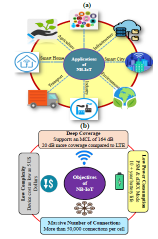
Figure 3: Applications and Objectives for NB-IOT: (a) Applications for NB-IoT and (b) Objectives for NB-IOT.
- Deep Coverage: The NB-IoT technology is designed to have both indoor and outdoor deep coverage. When compared to the conventional LTE network, NB-IoT provides up to 20 dB higher coverage [27]. NB-IoT has a maximum coupling loss (MCL) of 164 dB, whereas standard LTE has an MCL
of 144 dB. High coverage may be obtained, according to 3GPP specifications, by reducing bandwidth and increasing the number of data transmission repeats. Reduced bandwidth improves the PSD of the user, resulting in increased coverage. Nevertheless, there are two drawbacks to expanding coverage. Reduced bandwidth affects data throughput, whereas a high number of repeats raises data transfer delay and energy consumption [28].
- Low Power Consumption: NB-IoT products are designed to have a battery life of much more than ten years. To guarantee that NB-IoT products have such a long battery life, 3GPP Rel-12 and Rel-13 developed Power Saving Mode (PSM) and enhanced Discontinuous Reception (eDRX) modes. Both of these techniques strive to improve battery life in NB-IoT products by putting them into sleep mode when no data transfer is needed. PSM saves a significant amount of power and has a total sleep duration of 310 hours [29].
- Low Complexity: The cost of an NB-IoT device must be kept under $5. The infrastructure of NB-IoT has been simplified and improved to decrease devices price. When compared to the conventional LTE system, the network protocol volume, also the number of channels, signals, and transceivers, are reduced in NB-IoT. For both up-link and down-link transmissions, just one transceiver is used [30]. As NB-IoT only supports low-data-rate applications, it does not need a large memory, which leads to a decrease in the cost of devices.
- Support of Massive Number of Connections: The goal of NB-IoT is to serve over 50,000 users per cell. Using the NB-IOT system, the users transfer only a low data rate and delay-tolerant data. As a result, a single cell may effectively serve a massive number of devices. Furthermore, NB-IoT up-link transmission employs sub-carrier level transmission, which improves up-link resource use. For single-tone trans-
5. System Model of the Suggested Method
Figure 4 shows the transceiver system model for the proposed method using the STC technique with a typical OFDM system (STC-OFDM). The STC-OFDM was initially presented as a wireless approach in [31], which was proven to have similar results to OFDM while saving 50% of bandwidth by compressing OFDM symbols by half. In particular, the STC technique uses a spreading and combining mechanism in the transmitter and a symbol time extension (STE) approach in the receiver to expand the received symbol [32], as shown in Figure 4.
First, the transmitted bits are converted into the polar forms b0 and b1. Then, using Walsh codes c0 and c1, these polar forms are spread out. Finally, the spread data, b0c0 and b1c1, are combined. The spreading procedure is accomplished by the use of two spreading codes, which are as follows [33]:
![]()
Table 2 shows the spreading and combining operations in the STC scheme’s transmitter.
Table 2: Spreading and combining process
|
Transmitted bits |
Polar form of transmitted bits (b) | Walsh Code (C) | Spread data (bc) |
Combining Data (????) |
|||
| 1 | b0 = 1 | c0 = 1 1 | 1 | 1 | 0 2 | ||
| 0 | b1 = −1 | c1 = 1 −1 | −1 | 1 | |||
Following the spreading procedure, the spread data streams for each couple are joined as follows:
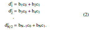
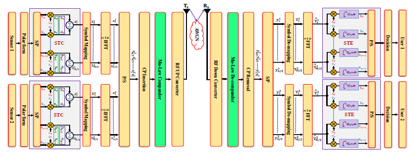
Figure 4: The transceiver system model for the proposed method using STC and µ−law companding technique.
- Figure 5 (a) depicts the waveform of the spreading process (b0c0) for the transmitted data b0 and Figure 5 (b) displays the waveform of spreading process (b1c1) for the transmitted data b1. While Figure 5 (c) shows the combined data (dc).
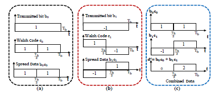
Figure 5: The wave-forms for: (a) spreading process of the transmitted data b0, (b) spreading process of the transmitted data b1 and (c) combined data
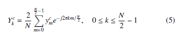
As displayed in Figure 4, the combining symbols are passed through the symbol mapping block to get the complex data symbols. The complex data symbol on the Kth sub-carrier is denoted by Xkc, k = 1,2,…, N/2. The resulting N/2 signals are applied to the N/2 input ports of an inverse fast Fourier transform (IFFT) processor.
A discrete-time OFDM symbol after IFFT is expressed as follows
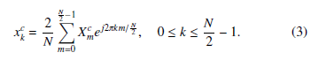
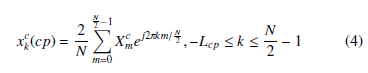
Where k represents the time index, N is the number of subcarriers, xkc is the kth OFDM symbol and Xm represents the mth transmitted data symbols. The cyclic prefix (CP) is inserted in front of each OFDM signal as a guard interval (GI) between subsequent OFDM symbols in OFDM systems to keep the orthogonality criterion and prevent inter-carrier interference (ICI) and inter-symbol interference (ISI). Where the length of CP must be greater than the maximum multi-path channel delay spread (Tcp ≥ τmax). A parallelto-serial (P/S) converter is applied to the resulting time domain symbols. A cyclic prefix (CP) of a suitable length (Lcp) is added to combat the effect of multi-path propagation and the transmitted OFDM symbol with CP is defined as follows:
To recover the transmitted data, the transmitter processing is functionally reversed in reverse order at the receiver side, as shown in Figure 4, to yield an approximated form of the binary information sequence. The kth received compressed OFDM symbol in the frequency domain is expressed as follows:
Following symbol de-mapping, the STE technique is used to retrieve the data streams, as shown in Table 3.
Table 3: De-spreading and combining processes
| ???? ???????? (????) | ?????? ∗ ???? |
?? ??̂ ?? = ???? ∗ ???? ?? |
?????? ∗ ???? |
?? ??̂ ?? = ???? ∗ ???? ?? |
| 0 2 | 0 2 | 1 | 0 − 2 | −1 |
To de-spread the received data, it is multiplied by the same code as the transmitter (c0 and c1). Then, integration throughout the bit period is as follows:
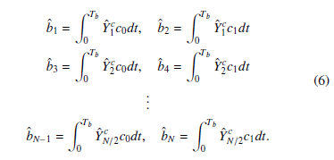
where Tb denotes the bit duration and bˆN is the detected Nth bit. The suggested approach is based on employing the STC technique twice in order to send data in the unused bandwidth, therefore doubling the number of connected devices. On the other hand, STE technique is employed twice on the receiver side to recover the data transferred from the transmitter to its original form, as shown in Figure 4.
6. Simulation Results and Discussion
This section discusses the numerical simulation and results for the proposed design. Table (4) provides the utilized simulation inputs of the system. Enhancement in PAPR, deterioration in BER, and power spectral density (PSD) are utilized as interesting performance metrics. Binary Phase Shift Keying (BPSK) modulation is used in this study for Fast-OFDM, STC-OFDM, and typical OFDM. Fast-OFDM is only applicable with one-dimensional modulation schemes, as was mentioned in [12]. Fast-OFDM and STC-OFDM systems are unable to handle higher-order modulation forms like Quadrature Phase Shift Keying (QPSK), which NB-IoT supports.
Nevertheless, a developed non-orthogonal wave-forms known as ”SEFDM” [34], may employ modulation schemes up to 16QAM at the cost of larger and more complexity. The improvement in PAPR is the difference between the PAPR of the conventional OFDM signal (original signal) and the PAPR of the STC-OFDM signal (i.e. Improvement in PAPR = PAPR of conventional OFDM – PAPR of STC-OFDM signal).Similarly, the difference between the BER of the original signal and the BER of the STC-OFDM signal is what is known as the BER deterioration.
Table 4: Simulation Parameters [12]
Parameter OFDM Fast-OFDM STC-OFDM
| Occupied Channel BW | 180 kHz | 90 kHz | 90 kHz |
| Bit rate (kbit/s) | 180 Kbps | 180 Kbps | 180 Kbps |
| Spacing frequency, ∆f | 15 kHz | 7.5 kHz | 15 kHz |
| Sampling frequency, fs | 1.92 MHz | 1.92 MHz | 1.92 MHz |
| FFT size, N | 128 | 128 | 64 |
| CP length,NCP | 32 samples | 32 samples | 16 samples |
| Modulation type | BPSK | BPSK | BPSK |
| Channel model | AWGN | AWGN | AWGN |
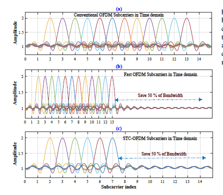
Figure 6: Sub-carrier allocation schemes for: (a) Typical OFDM, (b) Fast OFDM [12] and (c) STC-OFDM System [33].
In Figure 6, the sub-carriers for the traditional OFDM technique, FastOFDM, and the STC-OFDM are compared. Figure 6(a) shows a standard OFDM spectrum with orthogonally packed sub-carriers. The number of sub-carriers for Fast-OFDM is the same as typical OFDM, but the space between the sub-carriers is decreased to half as compared to typical OFDM as depicted in Figure 6(b). STC-OFDM reduces the number of sub-carriers by half while keeping the sub-carrier spacing, as it is clear in Figure 6(c). As a consequence, the bandwidth in Fast-OFDM and STC-OFDM is reduced by half, and the conserved bandwidth might be utilized to power more devices.
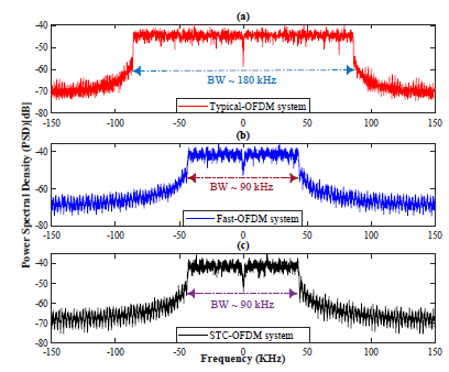
Figure 7: PSD for: (a) Typical OFDM, (b) Fast OFDM [12] and (c) STC-OFDM System [33].
Figure 7 shows the spectrum of STC-OFDM, Fast-OFDM, and typical OFDM. The first spectrum is for conventional OFDM and offers a bandwidth of 180 kHz; the second is for Fast-OFDM and compresses a bandwidth to 90 kHz; and the third is for STC-OFDM and also has a bandwidth of 90 kHz. The Fast-OFDM can transmit the same amount of data with half the bandwidth as compared to typical OFDM by decreasing the sub-carriers spacing to half, while the STC-OFDM sends the same amount of data with half the bandwidth as compared to typical OFDM by decreasing the number of sub-carriers to half, as it is seen in Figure 7. This means that they can save 50% of the bandwidth.
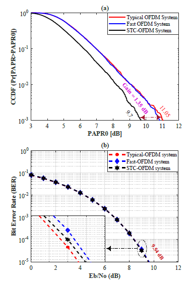
Figure 8: Performance comparison between Typical OFDM, Fast OFDM [12] and STC-OFDM System [33] based on (a) PAPR and (b) BER.
The STC-OFDM system uses half the bandwidth of the typical OFDM system to transmit the same amount of data. As a result, as illustrated in Figure 7(c), 50% of the bandwidth will be available for use to transmit the same amount of data. Furthermore, the STC-OFDM system increases system performance by decreasing the PAPR issue and avoiding BER deterioration. Figs. 8(a) and 8(b) indicate that the PAPR gain is 1.35 dB utilizing the STC-OFDM system with no BER deterioration. As for the Fast-OFDM, it saves half the bandwidth (Figure 7(b)) and prevents the BER degradation (Figure 8(b)), but it does not reduce PAPR, as seen in Figure 8(a).
From Figure 9 and Figure 10, it is clear that the transmitted data can increase to double using the same bandwidth. Figure 9 shows the transmitted picture, received picture, and PSD for the conventional OFDM system, while Figure 10 displays the transmitted pictures, received pictures, and PSD for the proposed scheme. The suggested approach concurrently transmits data from two sources (in our example, two sensors) with the same bandwidth as a standard OFDM system. Figure 9(c) and Figure 10(c) illustrate that the traditional OFDM technique and the suggested method have the same bandwidth, but the suggested approach has the benefit of being able to transfer twice as much information as the conventional OFDM technique, as seen in Figs. 9 and 10.
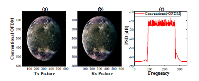
Figure 9: Send and receive a picture using a conventional OFDM system.
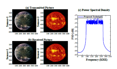
Figure 10: Send and receive two pictures using the proposed technique.
The time domain of the transmitted signal is measured after IFFT in the transmitter side for both the traditional OFDM system and the STC-OFDM method. When compared to a conventional OFDM system, the STC-OFDM scheme reduces OFDM symbol time by half for the same amount of data, as displayed in Figure 11(a). The transmitted information of a traditional OFDM system with 128 samples is transferred in 64 samples utilizing the STC-OFDM method, as it is clear in Figure 11(a). STC-OFDM is found to have similar performance to conventional OFDM, but with a 50% bandwidth savings. The number of IFFT is reduced by half when using the STC-OFDM technique and the PAPR is reduced as well. When employing the STC-OFDM technique, the PAPR improves by 1.58 dB, where the PAPR of typical OFDM is 11.35 and the PAPR of STC-OFDM is 9.77, as it is depicted in Figure 11(b). In addition to the improvement in PAPR, the STC-OFDM approach ensures that the BER of traditional OFDM and STC-OFDM is the same (i.e. the degradation in BER =0), as shown in Figure 11(c).
The STC-OFDM approach can save 50% of bandwidth, which means there is 50% of capacity that is not being used. As shown in Figure 4, the suggested method employs two STC techniques to use the entire bandwidth and double the amount of data transferred. Figure 12(a) shows that the suggested method has the same OFDM symbol time as a typical OFDM system, but it can send twice as much data, as displayed in Figure 10. The suggested approach offers the same PAPR as traditional OFDM and the same BER performance. The PAPR of a typical OFDM system and the suggested approach are shown in Figure 12(b), and it is evident that they are identical. Despite the fact that the suggested approach can transmit twice as much data as the typical OFDM system, it has the same BER performance, as illustrated in Figure 12(c).
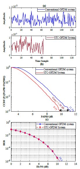
Figure 11: Performance comparison between typical OFDM and STC-OFDM technique [33] based on: (a) Time domain of Tx signal, (b) PAPR and (c) BER.
The µ-law companding approach reduces the high PAPR by enlarging small signals [35]. And therefore, it will be used with the proposed method to enhance system performance and reduce PAPR. Figure 13 shows the PAPR and BER for the suggested method using the µ−law companding technique. When the µ parameter is set to one (µ = 1), the PAPR improves by 3.22 dB with nearly no BER deterioration (BER degradation ≈ 0), as seen in Figure 13(a) and (b). Increasing the value of the µ parameter leads to decrease the PAPR and increase the enhancement in PAPR, as displayed in Figure 13(a). However, this enhancement will be at the expense of degradation in BER, as it is clear in Figure 13(b). Consequently, there is a trade-off between the enhancement in PAPR and the deterioration in BER. Table 5 summarizes the performance comparison of the proposed approach using µ−law Companding and traditional OFDM based on PAPR and BER.
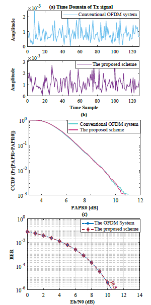
Figure 12: Performance comparison between conventional OFDM and the proposed method based on: (a) Time domain of Tx signal, (b) PAPR and (c) BER.
Table 5: PAPR improvement and BER deterioration for the suggested method using the Mu-Law technique.
| µ−law | Improvement in PAPR | SNR at BER 10−6 degradation |
| µ = 1 | 11.17 – 7.95 = 3.22 dB | 10.5 – 10.5 = 0 dB |
| µ = 4 | 11.17 – 5.1 = 6.07 dB | 11.4 – 10.5 = 0.9 dB |
| µ = 10 | 11.17 – 3.28 = 7.89 dB | 12.4 – 10.5 = 1.9 dB |
| µ = 100 | 11.17 – 2.17 = 9 dB | 17.5 – 10.5 = 7 dB |
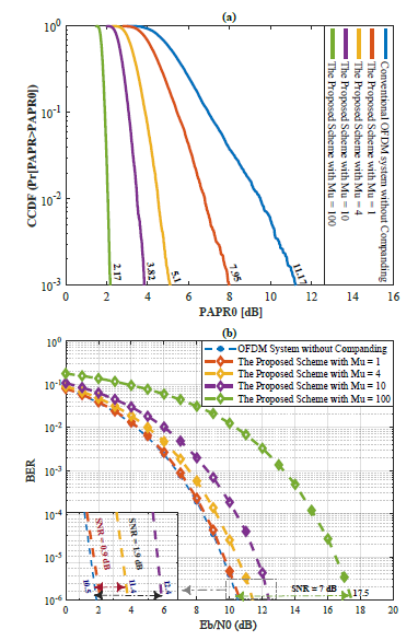
Figure 13: A typical OFDM system against the suggested method using µ-Law companding techniques: (a) PAPR and (b) BER.
7. Algorithms and Analysis of Complexity
This section explains the algorithms that utilized for the STC-OFDM and the proposed method. Algorithm 1 is designed to address the STC scheme and its inverse STC−1, while Algorithm 2 represents the transceiver of the suggested method (Transmitter and Receiver). Table 6 represents a comparison between the computational complexity of the proposed method using µ−law companding technique and the other techniques. The following assumptions are applied to calculate complexity: i) the complexity of subtraction equals the complexity of addition and ii) the complexity of division equals the complexity of multiplication. In the conventional OFDM system, it requires a total of (3N ∗ log2N − N) additions and (2N ∗ log2N − 2N) multiplications [36]. The Fast OFDM system has the same sub-carriers compared to the conventional OFDM system. Consequently, the Fast OFDM system has the same complexity as the conventional OFDM system.
The STC-OFDM system has half the sub-carriers as compared to the conventional OFDM and Fast OFDM systems. Therefore, the complexity of FFT in the STC-OFDM system requires a total of (N Log2 N2 – N2 ) additions and (N Log2 N2 – N) multiplications. To exploit the whole bandwidth, the STC approach is implemented twice in the proposed system. As a result, the complexity of the suggested approach requires a total of (3N ∗ log2N − N) additions and (2N ∗ log2N − 2N) multiplications. For the complexity of µ−law technique, it needs N multiplications and 4N addition [37]. And therefore, the complexity of proposed scheme using µ−law requires a total of (3N ∗ log2N + 3N) additions and (2N ∗ log2N − N) multiplications. It is clear from Table 6 that the complexity of the proposed method using µ−law technique is nearly the same as the conventional OFDM. Consequently, this indicates that the proposed method does not cause an increase in the complexity of the system.
Table 6: Computational Complexity Analysis.
| Techniques | No. Multiplications | No. Additions |
| Conventional OFDM [36] | 2N Log2N – 2N | 3N Log2N – N |
| Fast OFDM | 2N Log2N – 2N | 3N Log2N – N |
| STC-OFDM [36] | N Log2N2 – N |
3N Log2N2 – N2 2 |
| The proposed scheme | 2N Log2N – 2N | 3N Log2N – N |
| The proposed scheme using µ-law [37] | 2N Log2N – N | 3N Log2N + 3N |
Algorithm 1: : STC & STC−1 functions
At the Transmitter STC function
1: D= reshape(Data,length(D)/2,2); → Converting generated data from serial to parallel (Polar Matrix form) 2: W= hadamard(n);→ Generate walsh code & n = 2
3: SpreadData = D ∗ W; → Spreading Data
4: CombData= comb(S preadData); → Combining Data
5: Norm= CombineData/2;
6: f(X) = Norm(:,1) + j*Norm(:,2);
At the Receiver STC−1 function 1: W= hadamard(n);→ Generate walsh code & n = 2
2: Rx = Received Data in complex form ;
3: RealRx = real (Rx); → Peal Part
4: ImagRx = imag (Rx); → Imaginary part
5: Ry = [ RealRx; ImagRx ];
6: Despread1 = Ry*W(1,:); → De-spreading Data
7: Despread2 = Ry*W(2,:); → De-spreading Data
8: for k = 1 : length(Ry) do
9: CombData1 = sum (Despread1(k,:)) → Combining Data
10: CombData2 = sum (Despread2(k,:)) → Combining Data
11: end for
12: Y = [ CombData1;CombData2 ]; 13: f−1(X) = (Y+1)/2;
8. Conclusion
The major issue of low power wide area networks (LPWAN) is supporting a large number of devices while employing a limited spectrum of resources. This difficulty can be solved by employing narrow-band transmissions using NB-IoT. As a result, exponentially connected sensor nodes may be combined with additional benefits like better SNR and expanded coverage. Nonetheless, as the need for IoT services grows, more devices must be connected. The total number of linked devices is restricted because of the limited spectrum resources. The simulation results demonstrated that the STC-OFDM technique has the same performance as the standard OFDM system while conserving 50% of bandwidth, using half the number of sub-carriers to transmit the same data as the conventional OFDM system. According to simulation studies, the STC-OFDM scheme decreases OFDM symbol time by half for the same amount of data when compared to the standard OFDM system. When employing the STC-OFDM approach, the number of IFFT is decreased by half, as is the PAPR, where the PAPR improved by 1.58 dB with zero degradation in BER and nearly the same complexity.
|
1: Error = zeros (1,length(EbN0dB)); 2: nloop = 100; → Number of simulation loops 3: nsym = 1000; → Number of OFDM symbols for one loop 4: EbN0dB = 0:12; → Bit to noise ratio (Eb/N0) 5: for i = 1 : nloop do |
|
| 6: | D1 = Generate data for first source |
| 7: | D2 = Generate data for second source |
| 8: | X1 = STC(D1) → Apply STC Tech on the 1st source |
| 9: | X2 = STC(D1) → Apply STC Tech on the 2nd source |
| 10: | x1 = IFFT(X1); → Convert to time domain |
| 11: | x2 = IFFT(X2); → Convert to time domain |
| 12: | y1 = x1+ cp1; → Add cyclic prefix |
| 13: | y2 = x2+ cp2; → Add cyclic prefix |
| 14: | y = [ y1;y2 ]; → Data of the two sources |
| 15: | PAPR = zeros (1, N); → N is the number of IFFT, |
| 16: | for k = 1 : nsym do |
| 17: | Peak-power = max(|y|2); |
| 18: | Avg-power = mean(|y|2); |
| 19: | PAPR(k) = 10×log10(Peak-power/Avg-power); |
| 20: | end for |
| 21: | for q = 1 : length(EsN0dB) do |
| 22: | rx = y+ noise; → Received under AWGN channel |
| 23: | rcp1 = RemoveCP (rx1); →Remove CP of the 1st source |
| 24: | rcp2 =RemoveCP (rx2); →Remove CP of the 2nd source |
| 25: | Ry1 =FFT(rcp1); → Convert to frequency domain |
| 26: | Ry2 =FFT(rcp2); → Convert to frequency domain |
| 27: | Ry1 =STC−1(rcp1); → Apply the inverse STC Tech to 1st source |
| 28: | Ry2 =STC−1(rcp2); →Apply the inverse STC Tech to 2nd source |
| 29: | Ry = [ Ry1;Ry2 ]; → Data of the two sources |
| 30: | for m = 1 : length(Ry) do |
| 31: | if Ry(m) > 0.5 then |
| 32: | Ry(m) = 1 |
| 33: | else |
| 34: | Ry(m) = 0 |
| 35: | end if |
| 36: | end for |
| 37: | Error = BER (y , Output); → BER calculation |
| 38: | end for |
| 39: | D1 = R y(1 : length(Ry/2)); → Received Data of the 1st source |
| 40: | D2 = Ry(length(Ry/2)+1 : end); → Received Data of the 2nd source |
Algorithm 2: : The Transceiver of Proposed Technique
In this study, the proposed method was employed to exploit the unused bandwidth in order to double the number of connected devices without requiring more bandwidth while still maintaining the system’s performance. However, the suggested approach had the same PAPR and BER performance as the conventional OFDM system. When comparing STC-OFDM with Fast-OFDM, the two techniques had the same performance in sending the same amount of data with half the bandwidth (50% of the bandwidth), as compared to the typical OFDM. Additionally, they had the same BER compared to the typical OFDM. The STC-OFDM, however, outperformed the Fast-OFDM by 1.35 dB in terms of the PAPR problem. To improve the system performance in the proposed method and lower PAPR, the µ-law companding technique was combined with the proposed scheme. The µ value was carefully modified to get a good improvement in PAPR with no deterioration in BER. Based on the simulation results, the µ parameter was set to one (µ = 1) to improve the PAPR by 3.22 dB with almost no BER deterioration (BER degradation ≈ 0). In addition to the benefits of reduced PAPR, improved system performance, and double the number of connected devices, the proposed method using the µ−Law technique had roughly the same complexity as the conventional OFDM. Finally, raising the value of the µ parameter reduced PAPR and increased the improvement in PAPR. However, this improvement came at the cost of BER deterioration. As a result, there was a trade-off between the enhancement in PAPR and the deterioration in BER.
- Forbes, “2017 Roundup Of Internet Of Things Forecasts,” https://www.forbes.com/sites/louiscolumbus/2017/12/10/2017-roundup-
of-internet-of-things-forecasts/?sh=39f80e1b1480, 2017. - M. SYSTEMS, “Global IoT market to grow to 24.1 billion devices in 2030, gen- erating $1.5 trillion annual revenue,” https://transformainsights.com/news/iot- market-24-billion-usd15-trillion-revenue-2030, 2020.
- E. Rastogi, N. Saxena, A. Roy, D. R. Shin, “Narrowband Internet of Things: A comprehensive study,” Computer networks, 173, 107209, 2020.
- S. Liu, L. Xiao, Z. Han, Y. Tang, “Eliminating NB-IoT interference to LTE system: A sparse machine learning-based approach,” IEEE Internet of Things Journal, 6(4), 6919–6932, 2019.
- Y. Niu, C. Gao, Y. Li, L. Su, D. Jin, A. V. Vasilakos, “Exploiting device-to- device communications in joint scheduling of access and backhaul for mmWave small cells,” IEEE Journal on Selected Areas in Communications, 33(10), 2052– 2069, 2015.
- J. Chen, K. Hu, Q. Wang, Y. Sun, Z. Shi, S. He, “Narrowband internet of things: Implementations and applications,” IEEE Internet of Things Journal, 4(6), 2309–2314, 2017.
- H. Kroll, M. Korb, B. Weber, S. Willi, Q. Huang, “Maximum-likelihood detec- tion for energy-efficient timing acquisition in NB-IoT,” in 2017 IEEE Wireless Communications and Networking Conference Workshops (WCNCW), 1–5, IEEE, 2017.
- J. Liu, Q. Mu, L. Liu, L. Chen, “Investigation about the paging resource alloca- tion in NB-IoT,” in 2017 20th International Symposium on Wireless Personal Multimedia Communications (WPMC), 320–324, IEEE, 2017.
- H. Bello, X. Jian, Y. Wei, M. Chen, “Energy-delay evaluation and optimization for NB-IoT PSM with periodic uplink reporting,” IEEE Access, 7, 3074–3081, 2018.
- A. Adhikary, X. Lin, Y.-P. E. Wang, “Performance evaluation of NB-IoT cover- age,” in 2016 IEEE 84th Vehicular Technology Conference (VTC-Fall), 1–5, IEEE, 2016.
- P. Andres-Maldonado, P. Ameigeiras, J. Prados-Garzon, J. J. Ramos-Munoz, J. Navarro-Ortiz, J. M. Lopez-Soler, “Analytic analysis of narrowband IoT coverage enhancement approaches,” in 2018 Global internet of things summit (GIoTS), 1–6, IEEE, 2018.
- T. Xu, I. Darwazeh, “Non-orthogonal narrowband Internet of Things: A design for saving bandwidth and doubling the number of connected devices,” IEEE Internet of Things Journal, 5(3), 2120–2129, 2018.
- M. Mahbub, “NB-IoT: applications and future prospects in perspective of Bangladesh,” International Journal of Information Technology, 12(4), 1183– 1193, 2020.
- R. S. Sinha, Y. Wei, S.-H. Hwang, “A survey on LPWA technology: LoRa and NB-IoT,” Ict Express, 3(1), 14–21, 2017.
- Z. Zhang, “ZCNET: Achieving high capacity in low power wide area networks,” in 2020 IEEE 17th International Conference on Mobile Ad Hoc and Sensor Systems (MASS), 702–710, IEEE, 2020.
- Y. Chen, Y. A. Sambo, O. Onireti, M. A. Imran, “A Survey on LPWAN- 5G Integration: Main Challenges and Potential Solutions,” IEEE Access, 10, 32132–32149, 2022.
- R. Marini, K. Mikhaylov, G. Pasolini, C. Buratti, “Low-Power Wide-Area Net- works: Comparison of LoRaWAN and NB-IoT Performance,” IEEE Internet of Things Journal, 2022.
- A. Tusha, S. Dog˘ an, H. Arslan, “IQI mitigation for narrowband IoT systems with OFDM-IM,” IEEE Access, 6, 44626–44634, 2018.
- G. A. Akpakwu, B. J. Silva, G. P. Hancke, A. M. Abu-Mahfouz, “A survey on 5G networks for the Internet of Things: Communication technologies and challenges,” IEEE access, 6, 3619–3647, 2017.
- B. Qolomany, A. Al-Fuqaha, A. Gupta, D. Benhaddou, S. Alwajidi, J. Qadir, C. Fong, “Leveraging machine learning and big data for smart buildings: A comprehensive survey,” IEEE Access, 7, 90316–90356, 2019.
- V. Javidroozi, H. Shah, G. Feldman, “Urban computing and smart cities: To- wards changing city processes by applying enterprise systems integration practices,” IEEE Access, 7, 108023–108034, 2019.
- R. Du, P. Santi, M. Xiao, A. V. Vasilakos, C. Fischione, “The sensable city: A survey on the deployment and management for smart city monitoring,” IEEE Communications Surveys & Tutorials, 21(2), 1533–1560, 2018.
- L. Wan, Z. Zhang, J. Wang, “Demonstrability of Narrowband Internet of Things technology in advanced metering infrastructure,” EURASIP Journal on Wireless Communications and Networking, 2019(1), 1–12, 2019.
- V. Nair, R. Litjens, H. Zhang, “Optimisation of NB-IoT deployment for smart energy distribution networks,” Eurasip journal on wireless communications and networking, 2019(1), 1–15, 2019.
- W. Zhong, R. Yu, S. Xie, Y. Zhang, D. H. Tsang, “Software defined network- ing for flexible and green energy internet,” IEEE Communications Magazine, 54(12), 68–75, 2016.
- K. Wang, Y. Shao, L. Shu, C. Zhu, Y. Zhang, “Mobile big data fault-tolerant processing for ehealth networks,” IEEE Network, 30(1), 36–42, 2016.
- Y. D. Beyene, R. Jantti, O. Tirkkonen, K. Ruttik, S. Iraji, A. Larmo, T. Tirronen, J. Torsner, “NB-IoT technology overview and experience from cloud-RAN implementation,” IEEE wireless communications, 24(3), 26–32, 2017.
- J. Xu, J. Yao, L. Wang, Z. Ming, K. Wu, L. Chen, “Narrowband internet of things: Evolutions, technologies, and open issues,” IEEE Internet of Things Journal, 5(3), 1449–1462, 2017.
- S. K. Sharma, X. Wang, “Toward massive machine type communications in ultra-dense cellular IoT networks: Current issues and machine learning-assisted solutions,” IEEE Communications Surveys & Tutorials, 22(1), 426–471, 2019.
- Y. D. Beyene, R. Jantti, K. Ruttik, S. Iraji, “On the performance of narrow- band Internet of Things (NB-IoT),” in 2017 ieee wireless communications and networking conference (wcnc), 1–6, IEEE, 2017.
- M. S. El-Bakry, H. A. El-Shenawy, A. E.-H. A. Ammar, “A time inversion and symbol time compression (TI-STC) scheme for ICI cancellation in high mobility OFDM systems,” in 2017 Japan-Africa Conference on Electronics, Communications and Computers (JAC-ECC), 82–85, IEEE, 2017.
- M. S. Elbakry, A. Mohammed, T. Ismail, “Throughput improvement and PAPR reduction for OFDM-based VLC systems using an integrated STC-IMADJS technique,” Optical and Quantum Electronics, 54(7), 1–17, 2022.
- M. S. El-Bakry, H. A. El-Shenawy, A. E.-H. A. Ammar, “A symbol time compression for ICI reduction in high mobility OFDM systems,” in 2017 29th International Conference on Microelectronics (ICM), 1–4, IEEE, 2017.
- T. Xu, I. Darwazeh, “Transmission Experiment of Bandwidth Compressed Carrier Aggregation in a Realistic Fading Channel,” IEEE Transactions on Ve- hicular Technology, 66(5), 4087–4097, 2017, doi:10.1109/TVT.2016.2607523.
- A. Mohammed, M. Shehata, A. Nassar, H. Mostafa, “Performance Comparison of Companding-Based PAPR Suppression Techniques in OFDM Systems,” in 2019 8th International Conference on Modern Circuits and Systems Technolo- gies (MOCAST), 1–4, IEEE, 2019.
- M. Y. I. Afifi, M. S. Elbakry, E.-S. S. Soliman, A. Ammar, “An efficient technique for out-of-band power reduction for the eliminated CP-STC-shaped system for 5G requirements,” International Journal of Electrical and Computer Engineering, 10(5), 5306, 2020.
- A. Mohammed, T. Ismail, A. Nassar, H. Mostafa, “A novel companding tech- nique to reduce high peak to average power ratio in OFDM systems,” IEEE Access, 9, 35217–35228, 2021.