
The Design, Optimization, and Experimental Study of Hub and Axial Flux BLDC Motor Under Operating Conditions For Light Electric Vehicles
Volume 8, Issue 3, Page No 272-282, 2023
Author’s Name: Ozturk Tosun1,a), Kenan Toker1, Ozturk Tosun2, Necibe Fusun Oyman Serteller1, Vedat Topuz3
View Affiliations
1Electrical-Electronics Engineering, Faculty of Technology, Marmara University, Istanbul, 34854, Turkey
2Electrical-Electronics Engineering, Institute of Pure and Applied Sciences, Marmara University, Istanbul, 34854, Turkey
3Computer Technology Programming, Vocational School of Technical Sciences, Marmara University, Istanbul, 34854, Turkey
a)whom correspondence should be addressed. E-mail: ozturktosun@marun.edu.tr
Adv. Sci. Technol. Eng. Syst. J. 8(3), 272-282 (2023); ![]() DOI: 10.25046/aj080330
DOI: 10.25046/aj080330
Keywords: Axial flux BLDC motor, Hub BLDC motor, Efficiency

Export Citations
In this study, we conducted an experimental study and efficiency optimization of the outer rotor (hub) BLDC (brushless direct current) motor and axial BLDC motor for light electric vehicles. Both motors were investigated in the simulation environment and experimentally. The axial flux BLDC motor had a rated power of 10 KW, and a rated speed of 4550 rpm, while the outer rotor (hub) BLDC motor had a rated power of 1 KW and a rated speed of 300 rpm. The speed, efficiency, torque, and weight values of both motors were examined comparatively. The torque/volume values of the hub motor and axial flux motor were used as references for analysis. The hub motor and axial flux motors, with equal volume values, were simulated using ANSYS Electronics Desktop software. The simulation data were also compared with experimental studies. To optimize these motors using a genetic algorithm (GA), lower and upper limit values were determined for various parameters such as the outer and inner diameter of the stator, the outer diameter of the rotor, air gap length, slot height, axial length, air gap flux density, magnet thickness, and tooth width in the hub motor. Similarly, in the axial flux motor, parameters such as the outer and inner diameter of the stator, air gap length, slot height, air gap flux density, magnet thickness, tooth width, stator length, and rotor length were optimized using the GA method. The application of GA optimization has led to a 1.91% increase in the hub motor efficiency and a 3.45% increase in the axial motor efficiency.
Received: 02 March 2023, Accepted: 30 May 2023, Published Online: 25 June 2023
1. Introduction
Recently, BLDC motors are preferred mostly in automotive, home applications, and electric vehicles (EV) due to their high torque, wide speed region, high efficiency, and low maintenance requirement. Researchers are continuously studying ways to maximize the efficiency of electric motors in order to enable EVs to travel longer distances on a single charge, as the efficient use of battery energy is crucial [1]–[5]. Like other motors, BLDC motors consist of two main parts: a stator and a rotor. Generally, a stator, which is the fixed part, is located on the outside, while the rotor, the rotating part, is inside. However, due to the geometric shape of the rotor and the structure of the magnets, BLDC motors are manufactured in a way where the rotor is on the outer part and the stator is on the inner part, as it affects the torque and efficiency [6], [7]. In order to achieve high efficiency and high torque improvements the geometric structure of the BLDC motor is studied increasingly. In addition, features such as the winding method, pole type, and magnet type are also examined during the design phase[8]. The rotor design and optimization of the 10 KW BLDC motor with the desired torque and speed have been carried out in [9], considering the effect of rotor design on BLDC motor performance is effective on torque, speed, and efficiency. To optimize the two-wheel electric motor in terms of required torque, speed, size, mass, and cost, the effect of the air gap length on the efficiency was investigated between the determined mere limited values. In addition, the effect of stator inner diameter change on efficiency and torque was analyzed [10], [11]. Due to the increasing demand for energy and concerns about environmental pollution, the popularity of EVs has been on the rise. Among equivalent motors, BLDC motors are preferred due to their robustness, high efficiency, high power density, and wide constant power operation range. The use of NdFeB as a PM magnet in the rotor structure generally provides better performance compared to SmCo, AlNiCo, and Ceramic magnets[12]. Although induction motors are commonly used in electric vehicles today, their large size results in high magnetic losses and limited efficiency (around 85%). BLDC motors, on the other hand, are preferred for their high efficiency and environmentally friendly operating conditions[13]. Cogging torque is one of the major limitations of PM motors, and efforts during the design phase aim to reduce it[14], [15]. Different results in terms of efficiency, torque, torque density, and power density can be achieved between axial flux BLDC motors and radial flux BLDC motors using the same materials [16].
In this study, we compared the outer rotor and axial flux BLDC motors, taking the torque/volume ratio as a reference. These motors are illustrated in the 3D general schematics in Figure 1(b) and (c) respectively. The axial flux and hub BLDC motors were simulated using Ansys Electronics Desktop software. Additionally, current values, speed, and the torque of both motors were simultaneously investigated experimentally to validate the results obtained from the simulation environment. The study focused on examining efficiency speed, torque-time characteristics, air gap flux, and magnetic flux density distribution. By determining low and high limit values for the parameters that define the geometry of both motors, efficiency optimization was performed using the genetic algorithm method. Furthermore, adaptive multiple objectives were utilized for efficiency optimization in both motors.
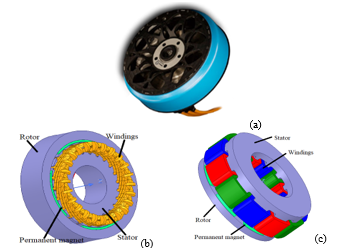
Figure 1. Wheeler motor scheme (a), Hub(b), Axial flux BLDC motor (c).
2. Design Analysis of Hub and Axial BLDC Motor
Geometric measurements of the Axial Flux and Hub BLDC motor were taken and the design was realized with the help of the Ansys/RMxprt package program. Efficiency, speed, torque, material consumption, and no-load flux density values were analyzed. Efficiency-speed curve, torque-time curve, and flux density distribution were observed with Ansys Maxwell 2D [17]. The specification of the axial flux and outer rotor BLDC motor are displayed in Table 1.
Table 1: Hub and axial flux BLDC motor specification.
| Definition | Axial | Hub |
| Nominal Power | 10 KW | 1 KW |
| Nominal Voltage | 72 V | 50 V |
| Slot Numbers | 12 | 18 |
| Pole Numbers | 8 | 24 |
| Axial length | 115.5 mm | 33.7 mm |
| Thickness of Magnet | 4 mm | 4 mm |
| Length of the air gap | 0.75 mm | 0.75 mm |
| Nominal Speed | 4550 rpm | 300 rpm |
| Torque/volume | 0.01 Nm/cm3 | 0.01 Nm/cm3 |
The hub BLDC motor has a unique design where the rotor is positioned outside and the stator is inside, which is the opposite of classical motors. The volume of the motor is determined by factors such as the inner and outer diameters of the stator, the length of the air gap, the thickness of the magnet, the inner and outer diameters of the rotor, and the axial length of the motor. On the other hand, the volume of the axial flux BLDC motor is determined by factors such as the length of the stator axial, length of the magnet axial, length of the rotor axial, and length of the air gap, in addition to the outer and inner diameters of the stator and the outer and inner diameters of the rotor. Based on these measurements and analytical calculations, simulations were conducted in the ANSYS/Maxwell software package for both motor designs[17]. The torque, speed, current, and efficiency values of the hub BLDC motor were investigated in both the simulation program and the experimental environment. The torque/volume (Nm/cm^3) ratio of both motors was compared with the reference. In Figure 2(a), the motor identifications of the hub motor; Dro, Dri, Dso, Dsi, bts (thickness of tooth), and hs (height of slot) are shown. In Figure 2(b), the motor identifications of the axial flux motor, such as the length of the rotor (Lr), the length of the stator (Ls), the thickness of the magnet (lm), the length of the air gap (g), the height of the slot (hs), and the thickness of the tooth (bts), are indicated.
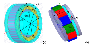
Figure 2. 3D view of hub motor and (a), 3D view of axial flux BLDC motor parameters (b).
Axial flux and hub BLDC motor having equal torque density have been compared. The advantages and disadvantages of these motors, which have different output powers and rated speeds, have been examined in terms of weight and volume. The outer diameter of the hub BLDC motor was calculated in Equation (1). The outer diameter (Dro) of the hub BLDC motor is affected by the stator outer diameter (Dso), magnet thickness (lm), air gap length (g), and rotor yoke height (hry), which is in the radial direction.
![]()
In Equation (2), the axial length of the axial flux BLDC motor was calculated. The axial length (LAF) of the axial flux BLDC motor affects the stator length (LS), rotor length (Lr), magnet length (lm), and air gap length (g), which is in the axial direction.
![]()
The air gap length of the axial flux and hub BLDC motors were kept equal. The torque density was given in (3). Torque density for the axial flux and hub BLDC motor are 0.01 Nm/cm3.
![]()
where T is the nominal torque.
The efficiency of the Axial flux and the hub BLDC motor was comparatively examined with respect to torque/volume. The parameters and calculation methods that influence the efficiency of both motors are the same. The input power applied to both motors is determined by the sum of the output power, friction and windage losses, copper losses, and core losses. Since the magnets on the rotor provide a constant flux source, there is no generation of a rotating magnetic field, and thus, core losses on the rotor are neglected. The losses are calculated in the iron core where the stator windings are located. In this case, the size of the stator volume and the characteristics of the ferromagnetic material affect the core losses. The same type of steel is used in both motors. Copper losses are dependent on the winding currents used in the stator slots and the electrical resistance of these windings. The phase resistance is determined by the cross-sectional area and length of the conductor. To determine the length of the conductor, parameters such as the stator’s outer diameter, slot height, number of slots, and slot pitch need to be considered. Friction and windage losses are assumed to be 1% of the rated power of the motors [17]. Motor efficiency is calculated as the ratio of output power to input power. The output power is obtained by subtracting copper losses, core losses, friction losses, and windage losses from the input power. The axial flux motor consists of two stators and a single rotor with magnets on both sides. Each stator package has a length of 48 mm. The outer diameter of the stator and rotor core is 150 mm, and the inner diameter is 80 mm. The stator windings have 14 conductors per slot with a conductor diameter of 2.58 mm. It has a two-layer winding and a whole-coil winding type. There are 2 parallel branches. The number of slots is 12. The rotor package length is 10 mm. The magnet thickness is 4 mm, and the radial length of the magnet is 34 mm. The number of magnet poles is 8.
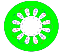
Figure 3. Axial flux BLDC motor winding type
Stator wire density, stator core steel density, rotor core steel density, and rotor magnet density are 8900 kg/m3, 7820 kg/m3, and 7500 kg/m3, respectively. The net steel weight in the axial motor stator core is 8.53 kg. Rotor net steel weight is 2.39 kg, magnet weight is 0.51 kg, and stator copper weight is 2.74 kg.
The hub motor is in a structure with the stator, which is the fixed part, in the inner part, and the rotor, which is the rotating part, in the outer part. The outer diameter of the stator core is 195 mm and the inner diameter is 128 mm. The number of conductors per slot in the stator windings is 42 and the conductor diameter is 2,304 mm. The two-layer winding and winding types are whole-coiled. The number of parallel branches is 1. The number of stator slots is 18. The rotor has an outer diameter of 213 mm and an inner diameter of 196.5 mm. The package length of the rotor is 33.7 mm. Magnet thickness is 4 mm.
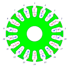
Figure 4. Hub BLDC motor winding type
Stator wire density, stator core steel density, rotor core steel density, and rotor magnet density are 8900 kg/m^3, 7820 kg/ m^3, and 7500 kg/ m^3, respectively. The net steel weight in the axial motor stator core is 2.51 kg. Rotor net steel weight is 0.65 kg, magnet weight is 0.44 kg, and stator copper weight is 1.59 kg.
D23_50 steel was preferred for the selection of ferromagnetic material in the stator and rotor core. It has been determined that there is an N42H magnet as the flux source in the rotor[18], [19]. The simulation outcomes for the hub BLDC motor are presented in Table 2.
Table 2: Axial and hub BLDC motor simulation results
| Definitions | Axial | Hub |
| Efficiency | 91.461% | 88.441% |
| Nominal torque | 20.991 Nm | 22.621 Nm |
| Nominal speed | 4550 rpm | 325 rpm |
| The flux density of stator yoke | 1.431 T | 1.061 T |
| The flux density of rotor yoke | 1.351 T | 2.171 T |
| The flux density of air gap | 0.781 T | 0.881 T |
| Total weight | 22.50 Kg | 5.21 Kg |
Figure 5(a) presents the efficiency-speed curve of the hub BLDC motor, while Figure 5(b) displays the efficiency-torque angle of the axial flux BLDC motor.
Based on the simulation results obtained from the Ansys/RMxprt program, the hub BLDC motor exhibited an efficiency of 88.44% with a rated speed of 325 rpm. Similarly, the axial flux BLDC motor demonstrated an efficiency of 91.46% at the rated speed of 4550 rpm.
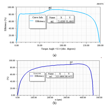
Figure 5. (a) Axial flux Efficiency Vs Torque (b)Hub BLDC motor Efficiency vs speed.
Figure 6 shows the axial flux BLDC motor flux density of the air gap curve. The air gap has an average flux density of 0.78 Tesla.
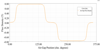
Figure 6. Axial flux BLDC motor air gap flux density
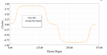
Figure 7. Hub BLDC motor air gap flux density.
Figure 7 shows the hub BLDC motor flux density of the air gap curve. The air gap has an average flux density of 0.88 Tesla. As seen in Figures 6 and 7, It has been aimed and composed that the flux density of the air gap was satisfactorily and uniformly distributed in both motors. Figure 8 shows the hub BLDC motor moving torque curve. The torque ripple value is 38 %.
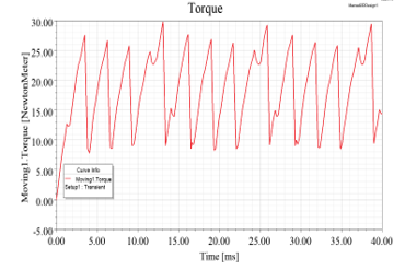
Figure 8. Hub BLDC motor moving torque
Figure 9 shows the axial flux BLDC motor moving torque curve. The torque ripple value is 28%.
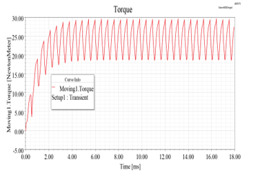
Figure 9. Axial flux BLDC motor moving torque
In Figure 10, the flux distribution of hub (a) and axial flux(b) BLDC motor has shown.
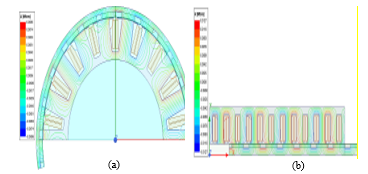
Figure 10. Flux distribution (a) Hub, (b)Axial flux BLDC motor
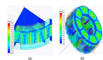
Figure 11. (a) Hub and (b) Axial flux BLDC motor flux density.
The flux distribution of the hub motor and the axial motor is shown in Figure 11. The dominant colors on the stator surface and stator inner were obtained as blue and green. This shows that the steel material used in the core doesn’t reach the saturation point. Both motors operate in efficient conditions. In Figure 11(a), the hub motor flux density of stator teeth is 1.43 T, the flux density of the stator core is 0.72 T, the flux density of the rotor core is 2.16 T, the flux density of the air gap is 0.88 T, the magnet flux density is 0.91 T. In Figure 11(b), the axial flux BLDC motor flux density of stator teeth is 1.56 T, the flux density of stator core is 1.40 T, the flux density of rotor core is 1.33 T, the flux density of air gap is 0.77 T, and the magnet flux density is 0.82 T.
3. Axial Flux and Hub BLDC Motor Experimental Studies
The stator windings of the axial flux and hub BLDC motor are connected in a 3-phase-star configuration. These motors are powered by a DC voltage source using a PWM trapezoidal strategy and inverters. At any given time, current flows through only two of the stator phase windings. Figure 12 illustrates the experimental setup.
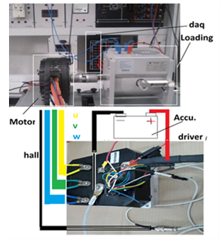
Figure 12: Axial Flux BLDC Motor Experimental Setup
The operating voltage of the axial flux BLDC motor is 72 volts. It has a 3-phase distributed winding structure. It is controlled by the chopped current control method. The maximum current level is 30 A, minimum current level is 10 A. It is fed with a direct current source. Voltage is applied to the stator windings through sensors that determine the rotor position. The direct current motor (25 Nm) has been coupled to the shaft of the axial motor as a load. As a result of the experiment, torque, current and speed values were measured. The efficiency value was determined according to these values. In Figure 13, the experiment results of the speed curve versus the efficiency of the axial flux motor are given.
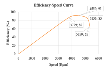
Figure 13. The efficiency-to-speed curve of the axial flux BLDC motor.
Table 3 presents the simulation and experimental results for the axial flux motor. The simulation results show a high level of agreement with the experimental results.
Table 3: Experimental and Simulation Results Of Axial Flux BLDC Motor.
| Axial Flux Motor | Efficiency (%) | Current(A) | Torque (Nm) |
| Simulation results | 91.46 | 149 | 20.99 |
| Experiment results | 91 | 140 | 19.36 |
In the experimental study for the hub motor, the control type is DC. Similar to an axial motor, voltage is applied sequentially to the stator windings. The operating voltage of the hub motor is set at 50 Volts.
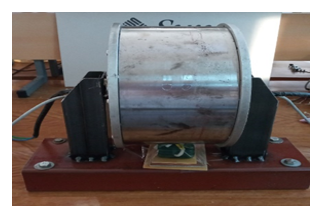
Figure 14: Experimental Setup of Hub BLDC Motor.
In Figure 15, the experiment results of the efficiency-speed curve of the hub BLDC motor are given.
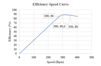
Figure 15: Hub BLDC Motor Experiment Efficiency-Speed Curve
The experimental and simulated outcomes for the hub motor are presented in Table 4. The experimental results indicate an efficiency value that is 0.25% higher, a current value of 2.32 A, and a torque value of 0.82 Nm greater than the simulation data.
Table 4: Experiment and Simulation Results of Hub BLDC Motor
| Hub BLDC Motor | Current (A) | Torque (Nm) | Efficiency (%) |
| Simulation results | 18.18 | 22.62 | 88.44 |
| Experiment results | 20.5 | 23.44 | 88.69 |
In Table 5, the main advantages and disadvantages of both the axial flux BLDC motor and the hub BLDC motor are highlighted.
Table 5: Comparison of Axial Flux and Hub BLDC Motor
| Motor Type | Power density | Speed |
Torque/ Weight |
Efficiency |
| Axial Flux | +++ | +++ | + | +++ |
| Hub | + | + | +++ | ++ |
+: normal; ++: medium; +++: high
4. Optimization of Efficiency to Axial Flux BLDC Motor and Hub BLDC Motor using Genetic Algorithm
Genetic Optimization (GA) is basically a five-step process. In the first step, the population of the problem to be solved is created. In the second step, the fitness value is calculated for each individual. In the third step, the selection is made using methods such as the roulette wheel and the tournament method. In this study, the roulette wheel selection method has been applied. Afterward, the crossover operation is performed on the chromosomes of the newly generated individuals. By applying the mutation operator to the resulting individual, an individual with better characteristics is obtained. The GA process continues until the best solution to the problem is found[20]. Table 6 shows the Axial Flux and Hub BLDC motor’s constant parameters.
Table 6: Axial Flux BLDC Motor and Hub BLDC Motor Constants
| Motor Type | Bsy(T) | Bry(T) | Bt(T) | Eph(V) | T(Nm) | N(rpm) |
| Axial Flux | 1.6 | 1.4 | 1.6 | 36 | 20.99 | 4550 |
| Hub | 1.6 | 1.4 | 1.6 | 25 | 22.62 |
325
|
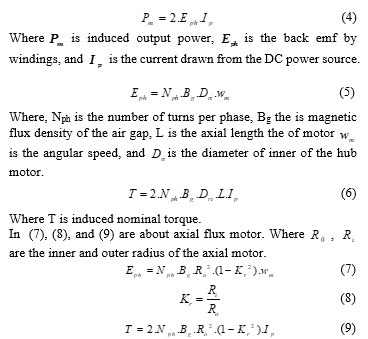
The variable parameters selected in the GA for the axial flux and hub BLDC motors are represented by equations (4) to (9). Equation (4) describes the electromechanical power of both motors. Equation (5) defines the back emf generated by the windings specifically for the hub BLDC motor. Equation (6) represents its electromechanical torque. In Equation (7), the flattop value of the back emf of phase is provided for the axial flux BLDC motor. Lastly, Equation (9) presents its electromechanical torque[21].
The GA was used to optimize the parameters affecting the efficiency of the hub BLDC motor and the axial flux BLDC motor. For the hub BLDC motor, variables such as the inner diameter of the stator, the outer diameter of the rotor, the length of the air gap, the height of the slot, the length of the motor axial, air gap flux density, magnet thickness, and tooth thickness were defined as optimization variables. The number of magnets, number of slots, conductors per slot, and conductor diameter were considered constant variables. Similarly, for the axial flux BLDC motor, variables such as the inner diameter of the stator, the outer diameter of the stator, the length of the air gap, the height of the slot, the axial length of the stator, the axial length of the rotor, air gap flux density, magnet thickness, and tooth thickness were defined as optimization variables, while the number of magnets, number of slots, conductors per slot, and conductor diameter were kept constant. The GA was implemented using codes created with the Delphi software package[22]. The optimization process involved defining the problem and evaluating the fitness value. A population of solutions was created, and the parameters affecting the efficiency of the motors were chosen as members of the population. The fitness value of each member in the population was determined, and the selection process was carried out using the roulette wheel method. After selection, the crossover operator (with a probability of 0.90) was applied to generate new individuals, and mutation (with a probability of 0.01) was performed. The optimum efficiency value of the hub BLDC motor (90.35%) was achieved in the 30th iteration, while the optimum efficiency value of the axial flux BLDC motor (94.91%) was obtained in the 50th iteration. The new values resulting from the GA for the variable parameters of the hub BLDC motor are presented in the right column of Table 7. Similarly, the new values resulting from the genetic algorithm for the variable parameters of the axial flux BLDC motor are given in the right column of Table 8. The efficiency values obtained at the end of the GA process for both motors can be found in the last column of Table 7 and Table 8.
Table 7: Hub BLDC Motor Variables
| Hub BLDC Motor | Low limits | Up limits | GA Results |
| The outer diameter of the stator | 190 mm | 196 mm | 195 mm |
| The Inner diameter of the stator | 122 mm | 128 mm | 125.27 mm |
| The outer diameter of the rotor | 210 mm | 215 mm | 211.41 mm |
| Air gap length | 0.5 mm | 1.5 mm | 1.449 mm |
| Height of slot | 18 mm | 25 mm | 19.51 mm |
| Axial length | 30 mm | 35 mm | 30.649 mm |
| The flux density of the air gap | 0.201 T | 1 T | 0.8301 T |
| Thickness of magnet | 3 mm | 8 mm | 4.919 mm |
| Thickness of tooth | 3 mm | 5 mm | 4.7411 mm |
| Efficiency | % | 90.351 % | |
Table 8: Axial Flux BLDC Motor Variables
| Axial Flux BLDC Motor | Low limits | Up limits | GA Results |
| The outer diameter of the stator | 145 mm | 155 mm | 145.28 mm |
| The inner diameter of the stator | 76 mm | 82 mm | 81.81 mm |
| Air gap length | 0.5 mm | 1.5 mm | 0.501 mm |
| Height of slot | 32 mm | 38 mm | 35.33 mm |
| The flux density of the air gap | 0.21 T | 1 T | 0.571 T |
| Thickness of magnet | 3 mm | 8 mm | 3.359 mm |
| Thickness of tooth | 3 mm | 5 mm | 3.149 mm |
| Length of stator | 45 mm | 55 mm | 45.499 mm |
| Length of rotor | 8 mm | 13 mm | 8 mm |
| Efficiency | 91.461 % | 94.911 % | |
5. The optimization of both the axial motor and hub motor using adaptive multiple objectives.
In the literature, there have been several studies focusing on the design optimization of BLDC motors using GA. These studies aim to achieve high efficiency and reduce torque ripple in classic BLDC motors[23]–[25]. In this particular section, the efficiency optimization is carried out using GA along with the adaptive multiple-objective method. For the axial flux BLDC motor, the variables considered are the stator outer diameter, stator inner diameter, stator axial length, rotor axial length, magnet thickness, and magnet radial length. The magnet pole number and stator slot number are kept constant throughout the optimization process.
Figure 16 illustrates the simulation values of efficiency plotted against the stator inner diameter (dsi) for the axial flux BLDC motor. At the highest efficiency point, the stator’s inner diameter is determined to be 75.8627 mm, resulting in an efficiency value of 92.3493%.
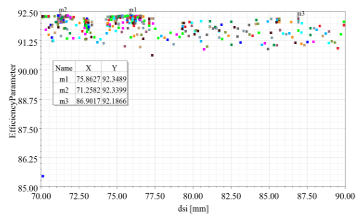
Figure 16. Axial flux BLDC motor efficiency-stator inner diameter)
The efficiency-stator outer diameter (dso) simulation values for the axial flux BLDC motor are given in Figure 17. At the highest efficiency (92.3493 %) point, the stator outer diameter is 156.3145 mm.
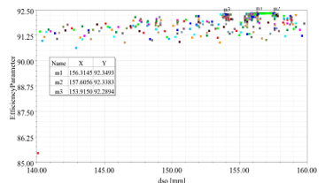
Figure 17. Axial flux BLDC motor efficiency-stator outer diameter
The efficiency-stator axial length (ls) simulation values for the axial flux BLDC motor are given in Figure 18. At the highest efficiency (92.3493 %) point, the stator axial length is 41.1670 mm.
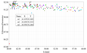
Figure 18. Axial flux BLDC motor efficiency-stator axial length
The efficiency-rotor axial length (lr) simulation values for the axial flux BLDC motor are given in Figure 19. At the highest efficiency (92.3493 %) point, the rotor axial length is 5.2167 mm.
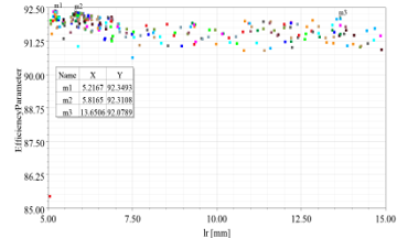
Figure 19. Axial flux BLDC motor efficiency-rotor axial length
The efficiency-magnet thickness (lm) simulation values for the axial flux BLDC motor are given in Figure 20. At the highest efficiency (92.3493 %) point, the magnet thickness is 4.5528 mm.
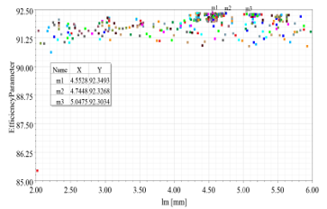
Figure 20. Axial flux BLDC motor efficiency-magnet thickness
The efficiency-magnet length (lmag) simulation values for the axial flux BLDC motor are given in Figure 21. At the highest efficiency (92.3493 %) point, the magnet length is 32.5770 mm.
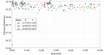
Figure 21. Axial flux BLDC motor efficiency- magnet length
In Figure 22, the highest efficiency value (92.3493 %) was obtained at the 982 th step according to the adaptive multiple objective optimizations.
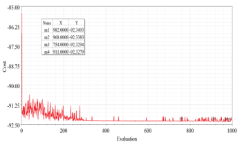
Figure 22. Axial flux BLDC motor adaptive multiple objective efficiency curve
The surface efficiency graph of the relationship between efficiency-output torque-stator outer diameter is given in Figure 23. Efficiency in the Z axis, output torque in the X axis, and stator outer diameter in the Y axis.
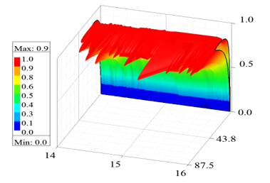
Figure 23. Axial flux BLDC motor efficiency-output torque-stator outer diameter
For the hub BLDC motor, outer diameter of stator, inner diameter of stator, axial length of stator, outer diameter of rotor, inner diameter of rotor, axial length of rotor, and thickness of magnet are defined as variables. The number of magnet poles and the number of stator slots are fixed. The efficiency-stator outer diameter (dso) values obtained according to the simulation results for the hub motor are given in Figure 24. At the highest efficiency (89.1632 %) point, the stator outer diameter is 194.8250 mm.
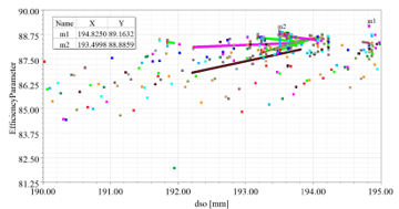
Figure 24. Hub BLDC motor efficiency-stator outer diameter
The efficiency-stator inner diameter (dsi) simulation values for the hub BLDC motor are given in Figure 25. At the highest efficiency (89.1632 %) point, the stator outer diameter is 126.0130 mm.
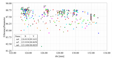
Figure 25. Hub BLDC motor efficiency-stator inner diameter
The efficiency-stator axial length (lsr) simulation values for the hub motor are given in Figure 26. At the highest efficiency (89.1632 %) point, the stator axial length is 32.0335 mm.
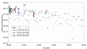
Figure 26. Hub BLDC motor efficiency-stator axial length
The efficiency-rotor outer diameter (dro) simulation values for the hub motor are given in Figure 27. At the highest efficiency (89.1632 %) point, the rotor outer diameter is 208.9875 mm.
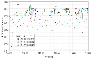
Figure 27. Hub BLDC motor efficiency-rotor outer diameter
The efficiency-magnet thickness (lm) simulation values for the hubBLDC motor are given in Figure 28. At the highest efficiency (89.1632 %) point, the magnet thickness is 3.9792 mm.
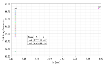
Figure 28. Hub BLDC motor efficiency-magnet thickness
The efficiency-rotor inner diameter (dri) simulation values for the hub motor are given in Figure 29. At the highest efficiency (89.1632 %) point, the magnet thickness is 197.1750 mm.
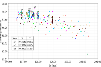
Figure 29. Hub BLDC motor efficiency-rotor inner diameter
In Figure 30, the highest efficiency value (89.1632 %) was obtained at the 878th step according to the adaptive multiple objective optimizations.
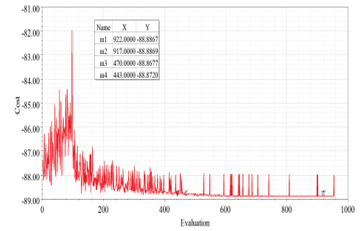
Figure 30: Hub BLDC motor adaptive multiple objective efficiency curve
6. Conclusions
In this study, the design and efficiency optimization of axial flux and hub BLDC motors were conducted through both theoretical (simulation) and experimental approaches. The main objective was to compare these two motor types and determine their suitability for light electric vehicles. The simulations were performed using the ANSYS/Maxwell package program, while the experimental data were collected to validate the simulation results. Parameters such as current, torque, speed, and efficiency were analyzed for both motor types. In the simulation environment, the axial flux BLDC motor achieved an efficiency of 91.46%, while the experimental results showed an efficiency of 91%. Similarly, the hub BLDC motor attained an efficiency of 88.44% in the simulation and 88.69% in the experimental setup. Furthermore, efficiency optimization was carried out using the GA method for both motor types, resulting in an efficiency of 94.91% for the axial flux BLDC motor and 90.35% for the hub BLDC motor. Additionally, adaptive multiple objective methods were employed to optimize the efficiency of both motor types, with the axial flux BLDC motor reaching the highest efficiency value of 92.3493% and the hub BLDC motor achieving 89.1632%. This comparative experimental study provides valuable insights for researchers working on light electric vehicle applications.
Conflict of Interest
The authors declare no conflict of interest.
- K. T. Chau, C. C. Chan, C. Liu, “Overview of permanent-magnet brushless drives for electric and hybrid electric vehicles,” IEEE Transactions on Industrial Electronics, 55(6), 2246 – 2257, 2008, doi: 10.1109/TIE.2008.918403.
- K. Toker, O. Tosun, N. F. O. Serteller, V. Topuz, “Design, Optimization and Experimental Study of Axial and Hub BLDC Motors in-Wheel Application for Light Electric Vehicles,” in MELECON 2022 – IEEE Mediterranean Electrotechnical Conference, Proceedings, 2022, doi: 10.1109/MELECON53508.2022.9842975.
- A. Eldho Aliasand, F. T. Josh, “Selection of Motor foran Electric Vehicle: A Review,” in Materials Today: Proceedings, 24(3), 1804-1815, 2020, doi: 10.1016/j.matpr.2020.03.605.
- J. A. Sanguesa, V. Torres-Sanz, P. Garrido, F. J. Martinez, J. M. Marquez-Barja, “A review on electric vehicles: Technologies and challenges,” Smart Cities, 4(1), 372-404, 2021, doi: 10.3390/smartcities4010022.
- D. Murgoci, M. Adam, “Research on the Influence of the Nominal Current on the Torque and Respectively on the Efficiency for the BLDC Motor with Variable Geometry,” in EPE 2022 – Proceedings of the 2022 12th International Conference and Exposition on Electrical and Power Engineering, 610 – 616, 2022, doi: 10.1109/EPE56121.2022.9959742.
- H. S. Shin, K. H. Shin, G. H. Jang, S. K. Cho, K. H. Jung, J. Y. Choi, “Experimental Verification and 2D Equivalent Analysis Techniques of BLDC Motor with Permanent Magnet Overhang and Housing-Integrated Rotor Core,” IEEE Transactions on Applied Superconductivity, 30(4), 1-5, 2020, doi: 10.1109/TASC.2020.2972233.
- F. Messine, B. Nogarede, J. L. Lagouanelle, “Optimal design of electromechanical actuators: A new method based on global optimization,” IEEE Trans Magn, 34(1), 299 – 308, 1998, doi: 10.1109/20.650361.
- M. Akar, M. Eker, F. Akın, “BLDC Motor Design and Application for Light Electric Vehicle,” Afyon Kocatepe University Journal of Sciences and Engineering, 21(2), 326-336, 2021, doi: 10.35414/akufemubid.889877.
- O. Tosun, N. F. O. Serteller, “The Design of the Outer-Rotor Brushless DC Motor and an Investigation of Motor Axial-Length-to-Pole-Pitch Ratio,”Sustainability(Switzerland), 14(19), 2022, doi:10.3390/su141912743.
- A. Vadde, S. Sachin, “Influence of Rotor Design in BLDC Motor for Two-Wheeler Electric Vehicle,” in ICPEE 2021 – 2021 1st International Conference on Power Electronics and Energy, 1-6, 2021, doi: 10.1109/ICPEE50452.2021.9358520.
- S. Tripathi, M. Gumma, and S. R. Potarlanka, “Virtual design optimization of a BLDC motor for a two wheeler electric cargo vehicle,” in 2022 2nd Asian Conference on Innovation in Technology, 1-6, 2022, doi: 10.1109/ASIANCON55314.2022.9909490.
- M. Toren, “Comparative analysis of the magnet effects on the permanent magnet BLDC motor performance used in electric vehicles,” Electrical Engineering, 104(5), 3411–3423, 2022, doi: 10.1007/s00202-022-01536-1.
- P. Chandran, K. Mylsamy, P. Umapathy, “Conceptual Design and Material Analysis of BLDC Motor Using FEA Tools for Electric Vehicle Applications,” Tehnicki Vjesnik, 29(3), 1010-1018, 2022, doi: 10.17559/TV-20210425201219.
- A. N. Patel, B. N. Suthar, “Double layer magnet design technique for cogging torque reduction of dual rotor single stator axial flux brushless dc motor,” Iranian Journal of Electrical and Electronic Engineering, 16(1), 58-65, 2020, doi: 10.22068/IJEEE.16.1.58.
- E. Yesilbag, Y. Ertugrul, L. Ergene, “Axial flux PM BLDC motor design methodology and comparison with a radial flux PM BLDC motor,” Turkish Journal of Electrical Engineering and Computer Sciences, 25(4), 3455-3467, 2017, doi: 10.3906/elk-1611-23.
- K. D. Prasetio, M. N. Yuniarto, “Design and Performance Test of Axial Halbach Brushless DC Motor with Power Density 1.5 Kw/Kg,” Jurnal Teknik ITS, 5(2), 664-667, 2017, doi: 10.12962/j23373539.v5i2.20658.
- A. S. Cabuk, S. Saglam, Ö. Üstün, “Investigation on efficiency of in-wheel BLDC motors for different winding structures,” Journal of the Faculty of Engineering and Architecture of Gazi University, 34(4), 1975-1985, 2019, doi: 10.17341/gazimmfd.571649.
- O. Tosun, N. F. O. Serteller, G. Yalcin, “Comprehensive Design and Optimization of Brushless Direct Current Motor for the Desired Operating Conditions,” in Proceedings of the 2021 25th International Conference Electronics, ELECTRONICS 2021, 1-6, 2021, doi: 10.1109/IEEECONF52705.2021.9467459.
- M. Çunkaş, R. Akkaya, “Design optimization of induction motor by genetic algorithm and comparison with existing motor,” Mathematical and Computational Applications, 11(3), 193-203, 2006, doi: 10.3390/mca11020193.
- P. R. Upadhyay, K. R. Rajagopal, “Genetic algorithm based design optimization of a permanent magnet brushless dc motor,” in Journal of Applied Physics, 97(10), 10Q516, 2005, doi: 10.1063/1.1860891.
- Y. Sun, M. Li, C. Liao, “Analysis of wheel hub motor drive application in electric vehicles,” in MATEC Web of Conferences, 100(4), 1-6, 2017, doi: 10.1051/matecconf/201710001004.
- D. Bruellmann, S. Sander, I. Schmidtmann, “The design of an fast Fourier filter for enhancing diagnostically relevant structures – endodontic files,” Comput Biol Med, 72, 212-217, 2016, doi: 10.1016/j.compbiomed.2016.03.019.
- M. Markovic, Y. Perriard, “Simplified design methodology for a slotless brushless DC motor,” IEEE Trans Magn, 42(12), 3842 – 3846, 2006, doi: 10.1109/TMAG.2006.884108.
- M. Markovic, P. Ragot, Y. Perriard, “Design optimization of a BLDC motor: A comparative analysis,” in Proceedings of IEEE International Electric Machines and Drives Conference, IEMDC 2007, 2, 1520-1523, 2007, doi: 10.1109/IEMDC.2007.383653.
- P. K. Shahri, V. Izadi, A. H. Ghasemi, “Design a High Efficiency and Low Ripple BLDC Motor Based on Multi-Objective Optimization Methods,” in Proceedings of the American Control Conference, 156-161, 2020, doi: 10.23919/ACC45564.2020.9147907.