Navigation Aid Device for Visually Impaired using Depth Camera

Adv. Sci. Technol. Eng. Syst. J. 8(3), 48–53 (2023);
 DOI: 10.25046/aj080306
People with visual impairment face daily struggle of navigating through unfamiliar places. This problem mainly caused by their lack of spatial awareness, i.e., the ability to estimate the distance between themselves and their surroundings. In order for visually impaired people to navigate independently, an effective navigation aid is required. The proposed navigation aid device utilizes depth camera to collect visual information of surrounding objects. Then, it represents the obtained visual data into stereophonic sound to notify the user directly through an audio device. The aid device is designed to be portable, comfortable, and easy to use. It can further be developed and upgraded to suit the needs of visually impaired users. Designed to be wearable, this proposed device was tested and received excellent score in portability, comfortability, and ease of use. The subjects were able to detect the position of obstacles in front of them with 92.47% accuracy, and could also estimate the distance of the object with Mean Absolute Error of 0.8. Examination on their navigation ability indicated that the subjects could stop before collision with an object and maneuvers through the gap between two parallel obstacles.
1. Introduction
There are approximately 285 millions visually impaired people in the world with 13.68% of them are totally blind and the rest suffer from low vision [1]. In their daily life, people with visual impairment face many difficulties, especially in navigation due to their inability to observe surrounding environment. The sense of sight is the most fundamental sense to navigate, to perceive the environment, and to identify as well as estimate distance of surrounding objects [2]. Of course, these cannot be achieved by visually impaired so that they have to use other senses to produce spatial perception.
In Indonesia, the infrastructure and public facilities for people with disability are limited. Compared to the others, facilities for visually impaired people are still insufficient. For example, considerable amount of public areas in Indonesia are not equipped with tactile paving [3]. Similarly, for public transportation such as bus and train, assistance for blind people is lacking so that it is very difficult for them to travel independently without the help of others.
In consideration of rapid development in technology, we should be able to help people with visual impairment in overcoming those limitations. With the aid of technology like camera, the visual ability could be conveyed though other senses. Some technologies have been implemented to help people with visual impairments, such as Blind People Guidance System using Stereo Camera [4], as well as facial expression recognition technology using deep learning [5]. However, there are still many other opportunities for application of technology to help people with visual impairments, such as navigate aid device for them to navigate independently .
Of those needs, a wearable navigation aid for visually impaired is necessary. This assistive device needs to be portable, comfortable, and also easy to use. It is also important for this device to have capability for further development, so that the users do not need to change or use more than this navigation aid. In this research, a depth camera is implemented as a sensor to collect visual information of surrounding environment in form of color and depth image. Hereafter, the visual information will be processed and represented though a sound to visually impaired. Visual representation in audio is carried out by various frequencies and amplitudes combination of stereophonic sound to reproduce a spatial perception.
The formatter will need to create these components, incorporating the applicable criteria that follow.
2. Research Method
In general, the method of this device could be divided into three: data collection, processing, and audio output. First, data is taken using a depth camera, which in this research uses Intel Realsense D435i [6]. This device is chosen because of the active stereo IR technology for depth imaging, equipped with a built-in IMU sensor. Its relatively small shape and low power consumption make this tool suitable for use as a wearable device. The depth camera will capture the user’s surroundings for processing. For data processing, NVIDIA Jetson Nano [7] is used as the embedded computing unit. Its compact form, low power, and computability make this device also suitable as a wearable device. After processing, the sound information consisting a combination of tones with certain frequency and pattern, which represents the position and the distance estimation of the obstacle, is output through the stereo headphone or earphone directly to the user.
The block diagram of this navigation aid system is shown in Figure 1.
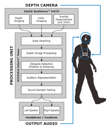
Figure 1: Block Diagram of Navigation Aid Device
2.1. Hardware Design
One of the important points of a wearable device is its design. The hardware design aims to make the device portable, comfortable, and easy to use. First is portability, where all the components used are small in size and light in weight. The power supply used is a battery, so all components must be able to work on a battery, which is why low power consumption is considered. For comfortability, it is necessary for a wearable support to put all the components used in one unit. Therefore, the users do not need to hold anything by hand and the device is integrated into their outfit. Last is ease of use, so that users can use this device independently every day, without the need for help from others or any complicated installation.
The following Figure 2 is the hardware design scheme with all of the components. Thereafter, an illustration of the wearing of this device is shown in Figure 3.
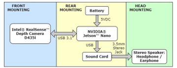
Figure 2: Hardware design scheme
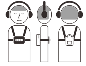
Figure 3: Wearable device installation design
The device is powered by a Lithium-Polymer battery 3 cells with 5200mAH capacity. Two devices that consume most of the power are NVIDIA Jetson Nano and Intel RealSense. NVIDIA Jetson Nano has 7-watt average power, while Intel RealSense consumes 3.5-watt power. The total power consumption is 10.5-watt. With the battery, our device could last about 6 hours of the use.
2.2. Software Design
In software design, there are several processes before an image can be represented in audio. First is data retrieval from RealSense™. Information such as depth images, color images, and IMU data can be retrieved from RealSense™ using the SDK provided by Intel® which was developed in open source [8]. The Intel® RealSense™ SDK 2.0, or librealsense, is equipped with a cross-platform library that can be used for various RealSense™ depth camera products. In this study, the Python wrapper from librealsense was used in the Python 3.0 programming environment.
In streaming mode, a callback function will be called every time a new data is available from the sensors. The callback function is run in different thread from the main loop and will store the data from the sensors to variables that could be accessed from the main loop. Therefore, the information could be obtained simultaneously and the main process could be run at the same time.
Next is depth image processing. Intel® RealSense ™ products are equipped with an API that is easy to use for various purposes, either with a GUI or in the form of a library, to retrieve data, both depth and color images, in standard units (millimetres for depth images and 8-bit RGB bits for color images). However, the results obtained cannot be used directly. Image processing is required so that the image can be used for the next step. There are several problems in depth images, including depth images and color images that have different viewpoints, unreadable depth values, and how to take values that represent an area of a certain size in the depth image. Depth image processing plays an important role so that the image can be further processed to extract the information. Figure 4 shows the results before and after depth image processing, and also the area that is being used for obstacle detection.
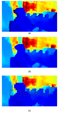
Figure 4. Depth image processing, (a) before processing, (b) after processing, (c) the area used for obstacle detection
The next step is detection of obstacles and their position. From the processed image, it will then be processed to detect existing obstacles. In this study, the position of the obstacle was limited into three parts: front left, front middle, and front right. Each position represents an area with a number of pixels in the depth image. The following Figure 5 is an illustration of the division of the depth image position with α, β, and γ angle for front left, front middle, and front right respectively. For vertical field of view, we used ±20°
For the depth distance in this study, the minimum depth distance is 40 cm, and the maximum depth distance is 160 cm. The meaning of the minimum depth distance is that if the object is closer than the minimum depth distance, the object will be considered very close to the minimum depth measurement of the camera. The meaning of the maximum depth distance is that if the object is farther than the maximum depth distance, then the object will be ignored or considered as no object. This value can be changed and adjusted according to the needs and convenience of each user, but in this study the determined value is used. Distance is also determined based on the accuracy of the depth in this system. In this study, a system depth accuracy of 40 cm was determined, which means that the depth information in the 40 cm range would be considered the same. Thus, there will be 5 categories. First, the undetectable depth beyond the maximum depth limit (160 cm). Second, namely the depth between the maximum limit to the depth accuracy in this case between 120 cm to 160 cm. The third is between 80 cm to 120 cm. The fourth is between 40 cm and 80 cm. The last is a depth that is smaller than the minimum depth limit (40 cm). At this stage the data obtained is in the form of three depth information (front left, front center, and right front) which have been classified into their respective categories (in this case categories 1 to 5).
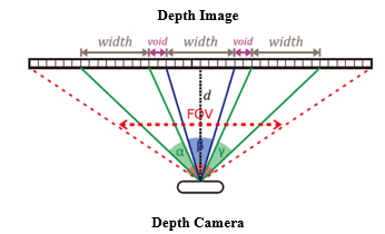
Figure 5: Position division in the depth image
After obtaining depth information to be conveyed in the form of position and depth or distance, it is necessary to represent the information in audio.
The most important thing about this step is to choose the right parameters to represent the depth information that is available. In this experiment, through try and error, the following parameter settings were obtained:
- For stereo audio, use the volume settings for the right channel and the left channel. When the object is on the front left, the audio will give full volume to the left channel. When the object is in front of the center, the audio will give half volume to the right channel and the left channel. Likewise, when the object is in front of the right, the audio will give full volume to the right channel.
- For frequency selection, after going through the try and error process, three types of frequencies are used, namely the tones C5, D5, and E5. The respective frequencies are 523.25 Hz, 587.33 Hz, and 659.26 Hz to represent the positions of the front left, front center, and front right, respectively. It is observed that the use of do re mi tones is easier for users to understand and remember.
- For duration, beeps pattern is used to provide the user with a perception of distance. The farther the object, the slower the beep, as well as the closer the object, the beep will be faster and the pause between beeps will also be faster. Since 5 categories have been determined, and for the first category there are no objects, there are 4 beeps sound patterns, each of which represents the depth distance category. In writing this report, to make it easier to describe the depth category, a simple name is used, namely “no object” for the category of depth further than the maximum limit, then respectively “far”, “medium”, “close”, and finally “very close” for categories where the object is closer than the minimum limit.
Sound information is conveyed through the stereo headphone through periodic cycle. The speed of one cycle will be adjusted according to the user’s capability. In one cycle, amplitude of the right audio will be decreased from maximum amplitude, while the left audio will be increased toward maximum amplitude. Three different tones will sound according to the Figure 5 with smooth transition. Therefore, the user could experience surround audio to visualize the spatial information.
3. Results And Discussion
3.1. Installation Test: Portability, Comfortability, and Ease of Use
As a wearable device, the first test is regarding the wear of the device Prototype design of the navigation aid for the visually impaired that has been assembled is installed to the subjects with visual impairment to test the design results. The results of installing a navigation aid on visually impaired subjects are as shown in Figure 6.
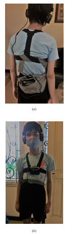
Figure 6: Installation of navigation aid device on visually impaired subjects, (a) back view, (b) front view
From this installation, we tested the portability, comfort and ease of use of the device in visually impaired subjects. After use for a while, visually impaired subjects were asked to provide an assessment of the value of portability, comfortability, and ease of use with several questions that had a correspondence with the three aspects being measured.
The answers to the questions are classified into positive answers, negative answers, or neutral answers. Answers which are positive answers include comfortable when used, not burdensome, easy to use daily, no difficulty in wearing the device, not limiting movement, not disturbing, etc. For answers that are negative answers include uncomfortable when used, burdensome, difficult to use, cannot be used daily, difficult wear in and / or remove the device, the device limits movement, annoying use of headphones / earphones. Answers that are neutral answers are answers that do not include positive or negative answers including answers with certain reasons or conditions such as a comfortable tool to use but within a certain period, the use of the tool does not limit movement if it is used at certain times, etc.
From the use experiments carried out on two blind subjects, the results are shown in table 1.
Table 1: Result of Qualitative Test On The Device Usage
| Question Number | Measured Aspect | Subject 1 | Subject 2 |
| I | Comfortability | Positive | Positive |
| II | Portability | Positive | Positive |
| III | Portability & Comfortability | Positive | Positive |
| IV | Ease of use | Positive | Neutral |
| V | Ease of use | Positive | Neutral |
| VI | Comfortability | Positive | Positive |
| VII | Comfortability | Positive | Positive |
In addition to qualitative questions, subjects were also asked to provide quantitative assessments for the value of portability, comfortability, and ease of use. Subjects were asked to give an assessment in the form of a number between one and ten (1-10) with a value of 1 being the lowest and 10 being the highest. The results of the quantitative assessment of two blind subjects are obtained in Table 2.
Table 2 : Result of Quantitative Test On The Device Usage
| Measured Aspect | Subject 1 | Subject 2 |
| Portability | 10 | 10 |
| Comfortability | 10 | 9 |
| Ease of use | 9 | 9 |
From the results of the hardware installation testing carried out, the portability, comfortability, and ease of use values were quite good by both subjects. Furthermore, for quantitative assessments with an assessment range of one to ten (1-10) with a value of 1 being the lowest and a value of 10 being the highest, an average value of 10 was obtained for portability, 9.5 for comfortability, and 9 for ease of use.
3.2. Functionality Test: Obstacle Position Detection
The overall system in the form of a navigation aid for the visually impaired is tested on a visually impaired subjects for the functionality of the device.
First, according to the system design, obstacle detection is grouped into three areas, namely obstacles in front of the left, obstacles in front of the middle, and obstacles in front of the right. From these three areas, each obstacle was tested in each area individually and also in combination to find out whether the blind subject could tell whether there were obstacles in that area.
The test was carried out with a combination of laying obstacles according to Table 3. From the tests carried out by two blind subjects, the results obtained in Table 4.
Table 3 : Obstacle Position For Testing
| Obstacle Position | |||
| Front Left | Front Middle | Front Right | |
| None | None | None | |
| Exist | None | None | |
| None | Exist | None | |
| None | None | Exist | |
| Exist | Exist | None | |
| Exist | None | Exist | |
| None | Exist | Exist | |
| Exist | Exist | Exist | |
Table 4. Result of functionality test on the device usage
| Test Subjects | Subject 1 | Subject 2 |
| True Positive (TP) | 12 | 9 |
| True Negative (TN) | 10 | 10 |
| False Positive (FP) | 2 | 4 |
| False Negative (FN) | 0 | 3 |
| Accuracy | 0.92 | 0.73 |
| Precision | 0.86 | 0.69 |
| Recall | 1 | 0.75 |
| F1 Score | 0.9247 | 0.7188 |
The results of this test is maximum accuracy of 92.47%. From the accuracy value obtained, this device can function properly to detect the presence or absence and position of obstacles.
For precision, the maximum value is 86%, and the maximum recall is 100%. From these two values, the F1 score was 92%.
3.3. Functionality Test: Obstacle Distance Estimation
Furthermore, a test is conducted to determine the distance estimation between the subject and the existing obstacles. In accordance with the system design, because the minimum and maximum depth values chosen are 0.4 meters and 1.6 meters with depth accuracy in the system design of 0.4 meters, so the depth is divided into 5 bucketized categories, namely distances above 1.6 meters detected as not obstacles, distances between 1.6 meters and 1.2 meters, the distance between 1.2 meters and 0.8 meters, the distance between 0.8 meters and 0.4 meters, and also the distance that is closer than 0.4 meters.
From the tests carried out on two blind subjects, the results are in Table 5.
From the tests that have been done, the best MAE value or mean absolute error is 0.8 (for bucketized categories). The obtained value is decent for the error rate in distance estimation. A small MAE value indicates that distance estimation errors occur for adjacent category.
Table 5 : Result of Obstacle Distance Estimation Test
| Subject | Subject 1 | Subject 2 | |
| Mean Absolute Error (MAE) | < 0.4 meter | 1 | 1 |
| 0.4 – 0.8 meter | 1 | 2 | |
| 0.8 – 1.2 meter | 1 | 3 | |
| 1.2 – 1.6 meter | 1 | 1 | |
| > 1.6 meter | 0 | 0 | |
| Average | 0.8 | 1.6 | |
3.4. Functionality Test: Simple Paths
The final test is the application of tools to blind subjects in walking on a predetermined route, to simulate some of the conditions that occur in daily navigation. In this test, there are two routes as illustrated in Figure 7.
In this test, there are two aspects tested. The first is whether visually impaired subjects can avoid collisions with the wall by stopping right before the wall without any other assistive devices. The second is whether the blind subject can spot and manoeuvre through the gap between two parallel obstacles.
From the conducted test, visually impaired subjects can stop before a collision occurs with the obstacle in front of them, in this case is a wall. Visually imapired subject can also manoeuvre through the gap between two parallel obstacles, in this case is a opened gate.
4. Conclusion
A navigation device is needed by visually impaired people to navigate in their daily life. Therefore, this navigation aid device is design to be portable, comfortable, and ease to use; as evidenced by questionnaire given to blind subjects after wearing this device.
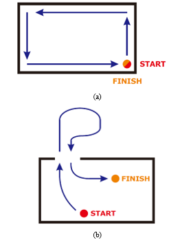
Figure 7: Simple paths for navigation aid device testing, (a) first route, (b) second route
The sensor used is Intel® Realsense D435i, which could capture color and depth images sufficiently, and is equipped with IMU. For this research, the information used is only the depth image, but could be developed further using various techniques to maximize the use of the information. The CPU used is Jetson™ Nano with very limited computational capabilities. For additional features and more complex object detection, a CPU that is more powerful with high computational capabilities is required, but still portable in size and could be powered by a battery.
The navigation aid functionality test shows the accuracy of the obstacle detection within three position division is 92.47% and the MAE error (mean absolute error) of the distance estimation to the obstacle is 0.8 for the obstacle distance setting that is less than 1.6 meters from the user. Furthermore, without the help of other tools such as cane, the users can stop before a collision with an obstacle in front, and walk through the gap between two parallel obstacles, according to testing on the simple paths.
This device testing is still limited to a few subjects. Henceforth, for future works, this device can be tested on more subjects with various ages, levels of visual impairment, and backgrounds. Additionally, different method of amplitude and frequency transition can also be explored to observe the effectivity of the device usage to the users.
Conflict of Interest
The authors declare no conflict of interest.
Acknowledgment
The authors gratefully acknowledge financial support from the Institut Teknologi Sepuluh Nopember for this work, under project scheme of the Publication Writing and IPR Incentive Program (PPHKI).
- D. Pascolini, S. P. Mariotti, “Global estimates of visual impairment : 2010,” Br. J. Ophthalmol, 96(5), 614–618, 2012.
- “Daily Life Problems Faced by Blind People.” [Online]. Available: https://wecapable.com/problems-faced-by-blind-people/. [Accessed: Oct. 30, 2019].
- E. Khoirunisa, D. Aries Himawanto, “The comparison of guide texture tiles for blind people in public areas between Surakarta and Nagoya city,” Jurnal Kajian Wilayah, 9(1), 34, 2018.
- I. P. Adi, H. Kusuma, M. Attamimi, “Blind People Guidance System using Stereo Camera,” in 2019 International Seminar on Intelligent Technology and Its Applications (ISITIA), Surabaya, Indonesia, 298-303, 2019, doi: 10.1109/ISITIA.2019.8937173.
- H. Kusuma, M. Attamimi, H. Fahrudin, “Deep learning based facial expressions recognition system for assisting visually impaired persons,” Bulletin of Electrical Engineering and Informatics, 9(3), 1208-1219, 2020.
- Intel, “Intel® RealSenseTM Camera D400 series Product Family Datasheet Rev. 01/2019,” 2019.
- NVIDIA, “DATA SHEET NVIDIA Jetson Nano System-on-Module Maxwell GPU + ARM Cortex-A57 + 4GB LPDDR4 + 16GB eMMC,” 2020.
- Intel, “IntelRealSense/librealsense: Intel® RealSenseTM SDK.” [Online]. Available: https://github.com/IntelRealSense/librealsense. [Accessed: Jun. 3, 2020].
No related articles were found.