
Achieving a High Isolation for the Triple-band MIMO Antenna in 5G/ Wi-Fi 6 Applications using Symmetric Parasitic Structure
Volume 8, Issue 2, Page No 139-147, 2023
Author’s Name: Nguyen Van Tan, Duong Thi Thanh Tua), Nguyen Viet Hung, Hoang Minh Duc
View Affiliations
Faculty of Telecommunication1, Posts and Telecommunications Institute of Technology, Hanoi, 100000, Vietnam
a)whom correspondence should be addressed. E-mail: tudtt@ptit.edu.vn
Adv. Sci. Technol. Eng. Syst. J. 8(2), 139-147 (2023); ![]() DOI: 10.25046/aj080216
DOI: 10.25046/aj080216
Keywords: Triple-band, MIMO, Parasitic structure, Fibonacci

Export Citations
Recently, the Multiple-input multiple-output (MIMO) antennas have been used a lot and attracted many researchers in advanced high-speed wireless communication systems. MIMO antennas are an essential part not only in access points but also in end-user devices. This technology allows a significant increase in channel capacity, but also lead to a challenge of minimize mutual coupling and in the meantime reserved antennas’ compact size. In this study, we propose a triple-band MIMO antenna design. By using a symmetric parasitic structure, isolation between radiation elements is significantly improved. Besides, each antenna element is designed using a combination of planar structure and 8 Fibonacci curves that makes it compact in size and easy to fabricate in the circuit board of 5G/ Wi-Fi 6 terminals. With a total dimension of 34.8* 68.2*1.6mm3, the proposed MIMO antenna design can operate at three bands of 2.4GHz, 3.5GHz, and 5GHz with wide bandwidths of 11.4%, 9.4%, and 14.58%, respectively. The results are analyzed based on simulation, measurement, and experiment.
Received: 04 January 2023, Accepted: 26 April 2023, Published Online: 28 April 2023
1. Introduction
Nowadays, the development of multimedia applications in end-user equipment such as portable devices, smartphones, and handheld gadgets is posing a great demand for high speed and reliability in wireless communication systems. MIMO technology is a great candidate to deal with this problem, which often requires implementation of MIMO antennas in both transceiver and receiver in wireless systems. Though this technology helps increasing channel capacity, it faces a challenge of depressing mutual coupling between close radiation elements [1]. There are several methods to obtain optimal isolation for MIMO antenna in end-user equipment that have been widely published. These methods increase isolation by using decoupling structure, parasitic element, neutralization line, orthogonal resonators, split ring resonator (SRR), and energy band gap [1]-[3]. These approach led to good isolation for UWB, single band, or dual band MIMO antenna. However, there are only a few publications with research for beyond dual-band MIMO antenna [4]-[17]. B. Bayarzaya et al. in [4] use a complex parasitic element to increase significantly isolation for triple-band MIMO antenna but the bandwidths are different at three bands and the radiation efficiencies are not detailed. The bandwidth is more uniform in the study of Xia Cao et al. in [5]. However, the antenna’s gain needs to be improved. Srinivasa Rao Pasumarthi et al. in [6] used DGS and via to achieve high isolation but the second band of their antenna is rather narrow for modern wide-band equipment. Others triple-band MIMO antenna researches presented in [7]-[9] can also get low mutual coupling but their total dimensions are relatively large. In consequence, these designs are not easy to ensure high isolation when implemented in compact handheld gadgets. Rupeng Liu et al. in [10] and Muhammad Usman et al. in [11] achieved compact MIMO antennas in their studies but the isolation in some operating frequencies still get under 20 dB.
In this work, we proposed a compact 1×2 MIMO antenna with low mutual coupling. Combined with shorting pin, the total size radiation patch is reduced by 71.25% which compared to a traditional disk antenna. The proposed antenna resonate at three operating band. They are 2.3 GHz, 3.4 GHz, and 4.8 GHz. The bandwidths are wide-bands that are 11.47%, 9.40% and 14.58%, respectively. To improve the isolation between antenna elements, a structures of symmetric parasitic is proposed. This structure leads to a significant reduction in mutual coupling, which reach 32.8 dB at 2.3 GHz. On the other hand, other parameters of the antenna are not affected and remain adequate. Antenna’s gain ranges from 2 to3.6 dBi, while radiation efficiency is kept in the range of 79-94%.
The rest of our study is set up as follows. In Part II, we present the single and MIMO antenna designs. The simulation and measurement as well as their analysis are studied in Parts III and IV, respectively. In Part V, we show the experimental results, based on IEEE 802.11 system. Finally, the conclusion of our study is present in Part VI.
2. Antenna Design
2.1. Triple-Band Single Antenna Basing on Fibonacci Curve
In this work, we use a triple-band antenna as an element of a MIMO antenna design. This is designed for wide-band wireless application at three well-know bands for 5G and/or WiFi 6 applications. We usse FR4 substrate to design both sigle and MIMO antenna. The thickness is 1.6mm, the relative permittivity is 4.4. The single antenna structure is shown in Figure 1. It consists of three main parts. They are a radiation patch including eight Fibonacci spiral curve slots, a shorting pin, and a defected ground as shown in Figure 1.
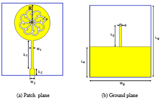
Figure 1. Fibonacci antenna structure
The recursive procedure of forming Fibonacci spiral curve is presented in Figure 2 [17].
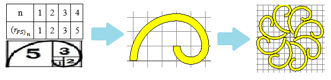
Fig 2. Fibonacci spiral curve for the proposed antenna
Each curve of Fibonacci sequence is calculated as follow:
![]()
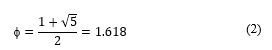
where n is changed from 1 to 4 which equal the number of arcs in spiral curve, f is golden ratio [6]. Value of f is determined by equation (2):
To get 2.4GHz band which is the lowest resonant frequency of the proposed antenna, we use the Equation (3) to calculate draft the radius of the circular radiation patch [12].
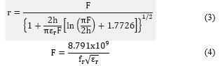
To reduce the antenna size, a shorting pin is introduced in a form of a strip line. This via connects two sides of the proposed antenna as shown in Figure 1 [13]. Its length is determined approximately as follow:
![]()
Table 1 presents the detail dimensions of the single antenna. It can be seen that, total antenna is 34.8*29.6 mm2 that is much compact comparing conventional 2.4GHz antenna.
Table 1. Dimension Values of Antenna
| Parameter | Value (mm) | Parameter | Value (mm) |
| Lg | 34.8 | Wg | 29.6 |
| L1 | 13.6 | W1 | 0.96 |
| L2 | 3 | W2 | 2.5 |
| L3 | 11.3 | R | 8.5 |
| L4 | 14 | p | 0.5 |
| d | 1 | r | 0.5 |
2.2. MIMO Fibonacci Antenna
Experiments with design of the unit cell of the parasitic structure using a basic square shape show reduction of mutual coupling for only one narrow band in MIMO antenna. To improve this the proposed unit cell structure includes a cross shape and four squares with gradual-changing-length slots as illustrated in Figure 3, Thus, this structure can reduce mutual coupling for multiple and wide bands.
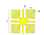
Figure 3. The proposed Symmetric Parasitic structure
In order to achieve significantly isolation of MIMO antenna for all three bands, the proposed 1×2 symmetric parasitic structure is placed as shown in Figure 4 with the close distance between elements of MIMO antenna. It is 9mm (0.072l) from edge to edge or 36.1mm (0.288l) from feeding point to feeding point.
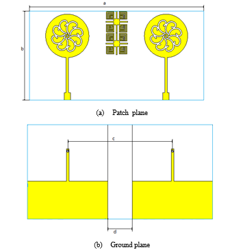
Figure 4. The design of MIMO antenna using symmetric parasitic structure
Table 2 presents the detail dimensions of the MIMO antenna. It can be seen that the antenna gets a compact size 4.8 ´ 68.2 ´ 1.6mm3.
Table 2. Detail Values of MIMO Antenna’s dimension
| Parameter | Value (mm) | Parameter | Value (mm) |
| a | 68.2 | e | 0.75 |
| b | 34.8 | f | 8 |
| c | 36.1 | g | 0.25 |
| d | 9 | h | 2.88 |
3. Simulation results and analysis
3.1. Fibonacci Antenna
In this part, the characters of the Fibonacci antenna is validated by simulation using CST Studio 3D EM. Firstly, the S11 of the single antenna are presented following three steps of forming structure of triple-band Fibonacci antenna as shown in Figure 5.
One can observe that the disk antenna gets only one resonant frequency of 8 GHz. With the same antenna size, the antenna with inscribed Fibonacci curves achieves three resonant frequencies and the lowest one is 4.4 GHz. Thus the antenna at the second step has not only form the multiband antenna but also decreased its size by approximately 45% compared to the disk patch. To further the antenna’s size reduction, a shorting pin like PIFA antenna that has lengthened on the ground plane is applied [13]. In this case, the lowest operation frequency of shorting-pin antenna is 2.2744GHz. It can be observed that there is a remarkable improvement of approximately 72% size decrease compared to the disk antenna. In additions, three bands of the proposed antenna are wide. They are 264MHz at 2.3GHz, 345MHz at 3.4GHz, and 815MHz at 4.6GHz. These bands are well-known bands of 5G and WiFi 6 applications.
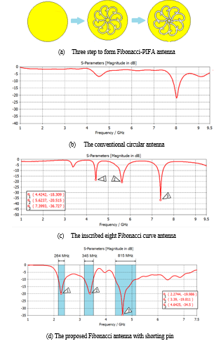
Figure 5 The simulation results of S11 parameter in three steps of forming the proposed antenna
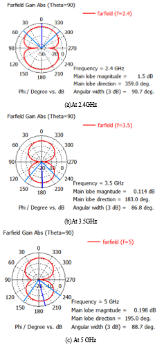
Figure 6. The simulation results of radiation pattern
Figure 6 presents the 2D radiation patterns of the Fibonacci antenna. It is clearly seen that the proposed antenna gets a considerably stable pattern with a dipole-like shape at all frequencies. In addition, a rather good value of gain is achieved. They are 1.83dB, 2.41dB and 2.89 dB at 2.4 GHz, 3.5 GHz and 5 GHz respectively. Besides, radiation efficiency are relatively high of over 94% at 2.4 GHz, 81% at 3.5 GHz and nearly 87 % at 5GHz as illustrated in Figure 7.
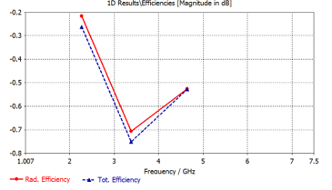
Figure 7. Radiation efficiency of Fibonacci antenna
3.2. The Triple-band MIMO Antenna
The simulation results of S11 and S12 parameters of triple-band MIMO antenna without symmetric parasitic structure are shown in Figure 8 with the distance of radiation patch of 9 mm. It can be observed that because of close distance between elements of MIMO antenna, the S12 of all operating bands are much above – 20 dB.
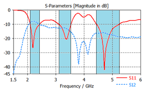
Figure 8. The value of S11 and S12 parameters without symmetric parasitic structure at 0.072l distance
In addition, due to the effect of mutual coupling, there is a distortion of MIMO patterns without decoupling structure, their shape are shown in Figure 9.
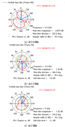
Figure 9. MIMO antenna’s pattern without symmetric parasitic structure
With the introduction of the proposed symmetric parasitic structure mentioned in section 2.2, the MIMO antenna’s isolation is significantly improved, especially at the first operating band. On the other hand, this structure is simple and compact, therefore it can be easily placed in other positions in the MIMO antenna for experiments. It can also be applied in other MIMO antenna designs. The S parameters of the proposed MIMO antenna using the symmetric parasitic structure are shown in Figure 10. The distance between radiation elements is still kept at 9 mm. It can be observed that the isolation of the MIMO antenna using symmetric parasitic structure is increased at all of the three operating bands, especially at 2.4 GHz where S21 is reduced by 60 dB. Similarly, at the 3.5 GHz it is 13.8 dB and at 5 GHz it is 5.7 dB.
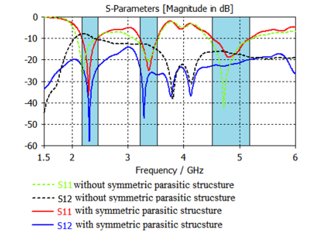
Figure 10. The value of S11 and S12 of MIMO antenna with and without symmetric parasitic structure
4. Measurement results
The proposed antennas are fabricate using FR4 substrate with thickness of 1.6mm and shown in Figure 11 and 12. The comparison of measurement and simulation results of both antenna’s reflection coefficient are drawn using Matlab software as present in Figure 13 and 14.
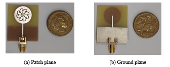
Figure 11. Fabricated single antenna
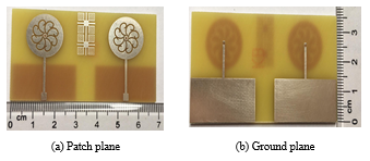
Figure 12. Fabricated MIMO antenna
It can be seen that both antennas achieve compact sizes of 34.8 x 68.2 x 1.6 mm3 and 29.8 x 38.4 x 1.6 mm3 for the MIMO and single antenna respectively. The circle patch’s size is very small with the area of approximate 232 mm2.
Measured results of S11 parameters show great similarity to the simulated ones as seen in Figure 13. Both single and MIMO antennas get the same resonant frequencies of around 2.4 GHz, 3.5 GHz and 4.8 GHz with large band width. They are over 10% at 2.4GHz, 9% at 3.5GHz, and 14% at 5GHz band. The measurement and simulation results agree well with each other. Besides, from Figure 14, the S12 parameter at all of three bands are under – 20 dB validated our proposed Symmetric Parasitic Structure. Thus the proposed decoupling structure can improve isolation for triple-band MIMO antenna.
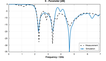
Figure 13. Comparison of measured and simulated S11 of single antenna
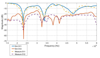
Figure 14. Comparison of measured and simulated S parameters of MIMO antenna with symmetric parasitic structure
5. Experiment results based on 802.11 systems
Two other performance parameters of the proposed antennas SNR (Signal to Noise Ratio) and RSSI (Received Signal Strength Indicator) are demonstrated by used Wi-Fi receiver as shown in Figure 15. These signal received by the proposed antennas will be compared with the result of a 2dB-gain dipole antenna which is commonly used for the Wi-Fi application. The test was held outdoors, with no obstructions in two weather conditions: sunny and light rain. Distance to signal source is from 0 to 100m (70m when it rains) with measuring positions 10m apart.
As showed in Figures 16 and Table 3 and Table 4, with sunny and dry weather, the proposed MIMO antenna has the best signal strength in both bands at close distances (from 0 to 30m) and the single antenna has better received signal strength at far distances.
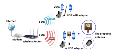
Figure 15. Test set up of the proposed antennas
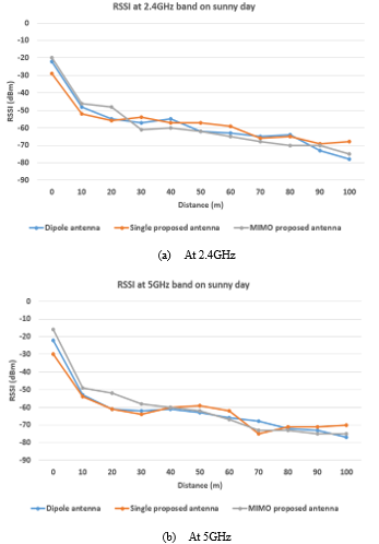
Figure 16. RSSI on sunny and dry weather
Table 3. RSSI (dBm) at 2.4GHz band on sunny day
| Distance (m) | Dipole Antenna | Single Proposed Antenna | MIMO Proposed Antenna |
| 0 | -22 | -29 | -20 |
| 10 | -48 | -52 | -46 |
| 20 | -55 | -56 | -48 |
| 30 | -57 | -54 | -61 |
| 40 | -55 | -57 | -60 |
| 50 | -62 | -57 | -62 |
| 60 | -63 | -59 | -65 |
| 70 | -65 | -66 | -68 |
| 80 | -64 | -65 | -70 |
| 90 | -73 | -69 | -70 |
| 100 | -78 | -68 | -75 |
Table 4. RSSI (dBm) at 5GHz band on sunny day
| Distance (m) | Dipole Antenna | Single Proposed Antenna | MIMO Proposed Antenna |
| 0 | -22 | -30 | -16 |
| 10 | -53 | -54 | -49 |
| 20 | -61 | -61 | -52 |
| 30 | -62 | -64 | -58 |
| 40 | -61 | -60 | -60 |
| 50 | -63 | -59 | -62 |
| 60 | -66 | -62 | -67 |
| 70 | -68 | -75 | -73 |
| 80 | -72 | -71 | -73 |
| 90 | -73 | -71 | -75 |
| 100 | -77 | -70 | -75 |
The results of the SNR in these two bands are presented in Figures 17 and Table 5 and 6. On 2.4GHz band, MIMO antenna’s results are the same Dipole antenna’s ones while the single Fibonacci antenna has better results. The SNR results at the 5GHz band are also the same RSSI results. Besides, the proposed MIMO antenna works well at close distances and the proposed single antenna works best at long distances. Thus, on sunny and dry weather, the two proposed antennas give quite similar and better results at some distances when compared to the Dipole antenna.
Table 5. SNR (dB) at 2.4GHz band on sunny day
| Distance (m) | Dipole Antenna | Single Proposed Antenna | MIMO Proposed Antenna |
| 0 | 100 | 100 | 100 |
| 10 | 100 | 100 | 100 |
| 20 | 100 | 100 | 100 |
| 30 | 92 | 100 | 92 |
| 40 | 84 | 92 | 84 |
| 50 | 74 | 92 | 74 |
| 60 | 74 | 88 | 74 |
| 70 | 70 | 84 | 68 |
| 80 | 68 | 80 | 64 |
| 90 | 58 | 74 | 62 |
| 100 | 58 | 64 | 60 |
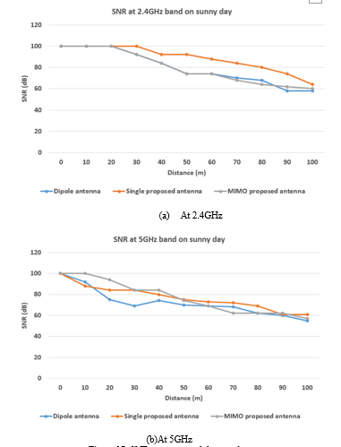
Figure 17. SNR on sunny and dry weather
Table 6. SNR (dB) at 5GHz band on sunny day
| Distance (m) | Dipole Antenna | Single Proposed Antenna | MIMO Proposed Antenna |
| 0 | 100 | 100 | 100 |
| 10 | 92 | 88 | 100 |
| 20 | 75 | 84 | 94 |
| 30 | 69 | 84 | 84 |
| 40 | 74 | 80 | 84 |
| 50 | 70 | 75 | 74 |
| 60 | 69 | 73 | 69 |
| 70 | 68 | 72 | 62 |
| 80 | 62 | 69 | 62 |
| 90 | 60 | 61 | 62 |
| 100 | 55 | 61 | 57 |
In rainy condition, the results of RSSI and SNR parameters are shown in Figures 18 and 19 and Tables 7, 8, 9 and 10. It can be seen that at both bands, the Dipole antenna has better signal strength than the two proposed antenna at close distances but worse at long distances.
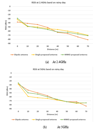
Figure 18. RSSI on rainy weather
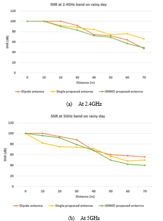
Figure 19. SNR on rainy weather
In the 2.4GHz band, the Dipole antenna has the best SNR results at close range, the single Fibonacci antenna achieves the best SNR at long distances and the MIMO Fibonacci one gets the worst results.
Table 7. RSSI (dBm) at 2.4GHz band on rainy day
| Distance (m) | Dipole Antenna | Single Proposed Antenna | MIMO Proposed Antenna |
| 0 | -38 | -32 | -29 |
| 10 | -41 | -49 | -48 |
| 20 | -44 | -50 | -52 |
| 30 | -51 | -54 | -56 |
| 40 | -63 | -56 | -62 |
| 50 | -66 | -60 | -63 |
| 60 | -74 | -64 | -67 |
| 70 | -81 | -70 | -71 |
Table 8. RSSI (dBm) at 5GHz band on rainy day
| Distance (m) | Dipole Antenna | Single Proposed Antenna | MIMO Proposed Antenna |
| 0 | -28 | -28 | -25 |
| 10 | -43 | -59 | -50 |
| 20 | -50 | -62 | -53 |
| 30 | -57 | -64 | -60 |
| 40 | -68 | -68 | -66 |
| 50 | -72 | -72 | -72 |
| 60 | -72 | -76 | -75 |
| 70 | -83 | -75 | -75 |
Table 9. SNR (dB) at 2.4GHz band on rainy day
| Distance (m) | Dipole Antenna | Single Proposed Antenna | MIMO Proposed Antenna |
| 0 | 100 | 100 | 100 |
| 10 | 100 | 100 | 100 |
| 20 | 100 | 92 | 90 |
| 30 | 92 | 88 | 83 |
| 40 | 74 | 84 | 72 |
| 50 | 72 | 74 | 69 |
| 60 | 64 | 76 | 57 |
| 70 | 47 | 66 | 49 |
Table 10. SNR (dB) at 5GHz band on rainy day
| Distance (m) | Dipole Antenna | Single Proposed Antenna | MIMO Proposed Antenna |
| 0 | 100 | 100 | 100 |
| 10 | 100 | 82 | 96 |
| 20 | 94 | 75 | 92 |
| 30 | 88 | 74 | 79 |
| 40 | 68 | 72 | 68 |
| 50 | 60 | 57 | 50 |
| 60 | 58 | 48 | 42 |
| 70 | 56 | 50 | 40 |
6. Conclusion
In this study, we proposed a compact triple-band MIMO antenna with eight Fibonacci slots and lengthened shorting pin with the symmetric parasitic structure. The overall MIMO antenna structure achieves a compact size of 34.8 x 68.2 mm2 based on the FR4 substrate. Three bands of MIMO antenna achieve wide bandwidths. They are 277.5 MHz at 2.4 GHz, 315 MHz at 3.5 GHz, and 675 MHz at 5 GHz. This antenna design is therefore suitable for wireless communications of 5G and Wi-Fi 6 applications. Furthermore, by using symmetric parasitic structure, the antenna achieves both extremely high radiating efficiency and high gain. On the other, despite the narrow distance of 0.072λ at 2.4 GHz resonant frequency between two radiation elements, the mutual coupling is kept well under -20 dB for all three bands. The high agreement between simulation and measured results validated the performance of the design.
Conflict of Interest
The authors declare no conflict of interest.
Acknowledgment
This study is partly supported by Vingroup Innovation Foundation (VinIF) under Postgraduate Scholarships Program
- Preeti Sharma, Rakesh N. Tiwari, Prabhakar Singh, Pradeep Kumar, and Binod K. Kanaujia, “Review MIMO Antennas: Design Approaches, Techniques and Applications,” Sensors, 2 (20), 7813, October 2022, doi:10.3390/s22207813.
- E. A. Andrade-González , J. A. Tirado-Méndez , H. Jardón-Aguilar , M. Reyes-Ayala , A. Rangel-Merino & Michael Pascoe-Chalke, “UWB four ports MIMO antenna based on inscribed Fibonacci circles,” Journal of Electromagnetic Waves and Applications, 2021, DOI:10.1080/09205071.2021.1873196.
- M. M. H. Mahfuz et al.: “Wearable Textile Patch Antenna: Challenges and Future Directions,” IEEE Access, 2022, vol.10, doi: 10.1109/ACCESS.2022.3161564.
- Batchingis Bayarzaya, Niamat Hussain, Wahaj Abbas Awan, Md. Abu Sufian, Anees Abbas, Domin Choi, Jaemin Lee, and Nam Kim, “A Compact MIMO Antenna with Improved Isolation for ISM, Sub-6 GHz, and WLAN Application,” Micromachines, 2022, 13, 1355, doi: 10.3390/mi13081355.
- Xia Cao, Yingqing Xia, Ling Wu, and Xiaolin Wu, “Tri-band MIMO antenna design based on characteristic modes manipulation,” International Journal of Electronics and Communications, 2022, 155, 154318 doi: 10.1016/j.aeue.2022.154318.
- Srinivasa Rao Pasumarthi, Jagadeesh Babu Kamili, Mallikarjuna Prasad Avala, “Design of Tri‑Band MIMO Antenna with Improved Isolation using DGS and Vias,” Wireless Personal Communications, 2019, doi: 10.1007/s11277-019-06799-9.
- Jing Luo, Peihua Wang, Xiaochen Chen, “Design of Compact Tri-Band MIMO Antenna Using Decoupling Structures for 5G Mobile Terminals,” 2021 Cross Strait Radio Science and Wireless Technology Conference (CSRSWTC), pp.43-45, 2021.
- Bazil Taha Ahmed, Darío Castro Carreras, Eduardo Garcia Marin, “Design and Implementation of Super Wide Band Triple Band‑Notched MIMO Antennas,” Wireless Personal Communications, 2021, 121:2757–2778, doi: 10.1007/s11277-021-08847-9.
- Omar Faruque, Md Saiful Islam, Md Sarwar Uddin Chowdhury, and A.K.M. Abdur Rahman Chowdhury, “A Four-element Triple-band MIMO Antenna for 5G Smartphone Applications,” 2nd International Conference on Sustainable Technologies for Industry 4.0 (STI),.2020.
- R. Liu et al.: “Neutralization Line Decoupling Tri-Band MIMO Antenna Design,” IEEE Access, 2020, Vol.8, pp.27018 – 27026, doi: 10.1109/ACCESS.2020.2971038.
- Muhammad Usman et al. , “Highly Isolated Compact Tri-Band MIMO Antenna with Trapezoidal Defected Ground Plane for 5G Communication Devices,.” 2020 International Conference on UK-China Emerging Technologies (UCET), 2020.
- Balanis C.A, “Antenna Theory: Analysis and Design,” Edition 3rd, Wiley, 2005.
- Duong Thi Thanh Tu, Nguyen Van Yem, Nguyen Tuan Ngoc, Nguyen Ngoc Tu, Nguyen Hong Duc, To Thi Thao, “4×4 Dual-Band MIMO Antenna with Low Mutual Coupling Using a Novel Structure of Neutral Line,” International Conference on Advanced Technologies for Communications (ATC2017), pp.80-85, 18-20 October 2017, Quy Nhon, Vietnam
- Manpreet Kaur, Hari Shankar Singh, “Design and analysis of high isolated super compact 2 x 2 MIMO antenna for WLAN application,” International Journal of RF and Microwave Computer-Aided Engineering, 2021, doi: 10.1002/mmce.22864.
- Xiao-Ting Yuan, Zhe Chen, Tianqi Gu, Tao Yuan “A Wideband PIFA-Pair-Based MIMO Antenna for 5G Smartphones,” IEEE Antennas and Wireless Propagation Letters, 2021, 20, pp. 371 – 375, doi: 10.1109/LAWP.2021.3050337.
- Babar Aslam Baloch, Zeeshan Zahid, Adnan Ahmed Khan “Self-Decoupled Dual Band PIFA for Wi-Fi 6E Smartwatch MIMO Applications,” Proceedings of 2022 19th International Bhurban Conference on Applied Sciences & Technology (IBCAST), 2022.
- Duong Thi Thanh Tu, Nguyen Van Tan, Nguyen Viet Hung, “Compact Triple-Band Antenna Based on Fibonacci Sequence for Wi-Fi/LTE-A/5G Below 6GHz Applications in IoT Devices,” 2019 6th Naforted Conference on Information and ComputerScience (NICS), pp. 309-313, 12-13 December 2019, Hanoi Vietnam.