Detecting the Movement of the Pilot’s Body During Flight Operations

Adv. Sci. Technol. Eng. Syst. J. 8(2), 71–77 (2023);
 DOI: 10.25046/aj080208
This research presents a “Multi-camera for pilot’s cockpit measurement system”, which uses four multi-view images to eliminate the instrument and human body shielding and record the touched area. That could record the body reaction time (velocity and acceleration) and trajectory of the tested personnel. Real-time conversion of multi-view images corresponding to the 3D skeletal joint coordinate information of the human body, which measure the human-computer interaction human factors engineering integration of limb reaction time and trajectory measurement system. Finally, make prototypes, test and optimize, and achieve the research on the optimal cockpit touch area by conducting multi-view image simulation feasibility experiment framework and measurement process method. Using multiple depth-sensing cameras to perform low-cost, standardized automatic labeling of human skeleton joint dynamic capture.
1. Introduction
Considering human factors engineering design is the foundation of workplace planning and the basis for product design development. Its anthropometric data is very important for work and daily life, and the correct anthropometric data is of great help to workplace design, work planning and human-machine interface safety considerations. Due to the rapid development of camera technology in recent years, the image resolution has also been greatly improved. It can achieve a certain accuracy in experimental measurement applications. It can also be used for non-contact optical measurement with image analysis software. The human motion tracking technologies are included marker/markerless. Markerless motion applications are such as sports science. For example, in [2], the author presented captured of an athlete for sport research. The basic concept of digital photogrammetry is to locate the specific punctuation point of the measurement position in the image, compare the measurement punctuation position at different times, and then obtain the displacement of the measurement point. Camera measurement can get good measurement results as long as the punctuation points in the image are clearly visible. The image analysis method has the advantages of non-contact measurement method, and the influence of the local environment on the measurement is also very small. Therefore, this research chooses to apply the camera to develop the metrology technology.
In [3], the author presented the DIC (Digital Image Correlation) method with 3D stereo vision. The DIC method is applied to 3D deformation measurement. The 3D-DIC method is applied to the surface profile measurement research. Whether 3D-DIC or other non-contact image measurement systems is composed of stereo cameras. The distance and angle between two cameras overlap within a certain range. When the measurement range exceeds the visible range of the two image capture devices, only partial images of the object can be captured. The camera must be adjusted according to the different shapes of the object, and the image capture device must be re-installed. The range of camera angle of view and the need for continuous calibration of the adjusted camera are application constraints. It is necessary to simplify and repeat the definition of the relationship between the coordinates of the calibration measurement system and the object to be measured.
In order to solve the aforementioned problems, in [4], the author presented a two-axis parallel motion mechanism for vertical and horizontal motion. The device uses a servo motor as a positioning control, and is mounted on a camera device. That can precisely control the camera’s imaging angle. Both X and Y axes operates are independently, and will not become the load of another servo motor for image capture and analysis. Using three cameras to build a semi-circular geometric multi-camera imaging platform system [5]. Those multi-camera are set with a semi-circular measuring rod and the optical axes of the multi-cameras co-intersect at a point in space. The mechanism can be used to adjust the spacing with the semi-circular measuring rod. With the superimposition feature of multiple cameras, the system can increase the range of overlapping areas of 3D reconstruction feature points and the correction parameters established inside. It’s required for on-site measurement and reconstruction of 3D information. The field of view and simplify the procedure of repeatedly defining and determining the relationship between the coordinates of the calibration measurement system and the object to be measured.
The image analysis techniques and photogrammetric image acquisition are precisely and quickly measure. The 3D-based machine vision in metrology is popular. The aircraft pilot’s cockpit design needs to meet pilots’ feasibility in 5~95% of body figuration. MIL-STD-1333 [6] is defined the pilot’s reach zone and MIL-STD-1472 [7] is defined schematic diagram of the pilot’s cockpit reach zone area. The analysis of actions related for the pilot’s reach zone. That is necessary to detect the human head and movement of the upper and lower limbs.
The conventional technology can only measure the static human body of a single person, and it is necessary to manually adjust the human body measurement data multiple times, manually select the measurement mark points, and manually edit and superimpose the 3D human body model. This innovative technology provides dynamic human trajectory calculation reaction time, and can automatically mark human bone joints and superimpose standardized 3D human joint coordinates.
Most studies discuss pilots’ eye gaze strategies, is lack of pilot’s movement monitoring with optical tracking in the aircraft cockpit [8-12]. The aim of this research evaluate human-computer interaction and human factors engineering on multi-camera for pilot’s cockpit measurement system. Using multiple depth-sensing cameras to perform dynamic capture and record the reaction time and trajectory of the subject’s limbs, including real-time conversion of multi-view images corresponding to the 3D skeletal joint coordinate information of the human body.
2. Research methods
Fig. 1 is the aircraft pilot’s cockpit design for pilots’ feasibility in 5~95% of body figuration. When pilot wear a flight suit, comfort, easy operation and visual display, are the requirement to be concerned. And the maneuverability of control and display of information have to be effectively functioned under the constant high G (gravity) force condition. At present, the evaluation of pilots’ human factors engineering, is used the research of physical model and interview as the basis for the adjustment of the aircraft cockpit design. The information presents from the research is difficultly analyzed and takes lots of time and manpower. The common improper design of human factors engineering are showed as: over-sized helmet, close instrument panel, the pilot body touches the control lever, the hand is too short to reach the control lever, and the pilot’s long foot touches the instrument panel.
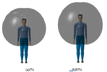
Figure 1: The aircraft pilot’s cockpit design for pilots’ feasibility in 5~95% of body figuration
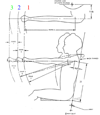
Figure 2: MIL-STD-1333 [6] is defined the pilot’s reach zone.
Fig. 2 is MIL-STD-1333 [6], that defined pilot’s reach zone. The pilot reach zones are divided into three areas. (1) ZONE 1 [Natural arm-reach mechanism zone (shoulder strap locked)]: Both hands can operate naturally to reach in ZONE 1, while shoulders are attached to the back of the seat, and arm and shoulder muscles do not need to be stretched forcefully. (2)ZONE 2[Maximum arm-reach mechanism zone (shoulder strap locked)]: The maximum arm-reach mechanism zone is defined while arm and shoulder muscles are stretched to the maximum. All the critical control devices in flight are included within ZONE 2. (3)ZONE 3 [Maximum arm-reach mechanism zone (shoulder strap unlocked)]: The maximum mechanism arm-reach zone is defined while shoulders are as far forward as possible and arms fully reach. All the none-critical and none-essential control devices in flight are included within ZONE 3.
Fig 3 is MIL-STD-1472 [7] defined the touched area of aircraft cockpit. The motion of pilot’s head and upper limbs are needed to detect in accord with the analysis of pilot’s motion around touched area. To record and analyze the posture the pilot’s upper body muscles touching the cockpit reach zone and motions around area, we proposed to use four cameras to build up a multi-view image. The pilot executes the instrument operation according to the instructions of different subjects. The system analyzes where each instrument should be located in tested pilot’s touching area by image processing and motion detection of human upper limb.
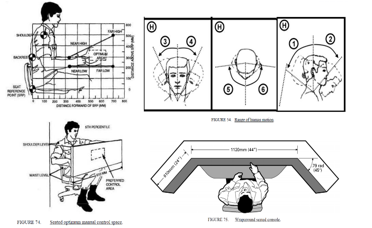
Figure 3: MIL-STD-1472 [7] defined the touched area of aircraft cockpit
Fig. 4 is the schematic diagram of multi-view image measurement system setup with human factors engineering. First, simulate the pilot operation in different positions and height of instrument panel. Then, utilize the concept of human skeleton detection to measure the position which the pilot reads or touches the instrument. Subsequently, develop an automatic measure evaluation system in pilot’s reachable areas, with the utilization of multi-view imaging by four cameras and 3D machine vision method.
Fig. 5 is the multi-camera for pilot’s cockpit measurement system. Using multiple depth image sensors to measure and track the operation of cockpit personnel with optical measurement technology, that measure pilot’s reaction time and trajectory. Where, C0 is placed in front of the pilot for pilot’s head and eyes. C1 is above the pilot’s seat. The head is defined as the origin of the measurement. The reachable area of the upper limb in the X-Y plane is recorded in different conditions. Both C2 and C3 are arranged on the left and right sides of the pilot respectively. That is exclude the shielding of instruments and the human body and record the contact area of the X-Z plane. This technology proposes multi-view images to correspond to human body 3D skeletal joint coordinate information and explores human-computer interaction human factors engineering integration of limb reaction time and trajectory measurement system.
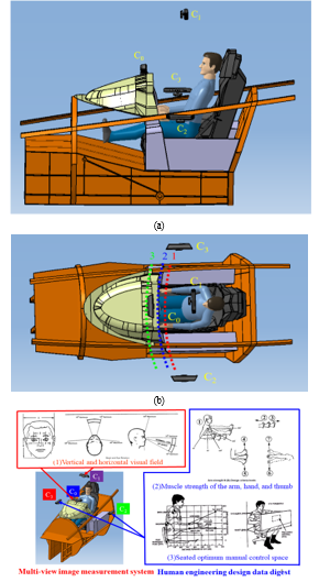
Figure 4: Schematic diagram of multi-view image measurement system setup with human factors engineering
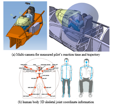
Figure 5: The multi-camera for pilot’s cockpit measurement system.
3. Experimental result
In order to verify the feasibility of a multi-view measurement system, the schematic diagram of simulated multi-view image setup is showed as Fig. 6. Where, fig 6(a) is a top view, Fig. 6(b) is a right view and Fig. 6(c) is a front view. Fig. 7 is the simulated multi-view image, in which Fig. 7(a) uses a hemispherical calibration target for 3D analysis, and the simulation result is shown in Fig. 7(b). The C0 image is placed in front of the pilot to measure the head and eyes.
Fig. 7(c) is the C1 image is on the top of the seat. The pilot’s head is defined as the measurement reference point. The upper limbs in the X-Y plane can be touched under different constraints with MIL-STD-1333 definition. Figs. 7(d) and (e) are C2 and C3 image respectively, which are installed on the left and right sides of the pilot. Those exclude the cockpit instruments and human body shielding and record the touched area on the X-Z plane.
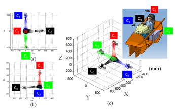
Figure 6: Schematic diagram of simulated multi-view image setup
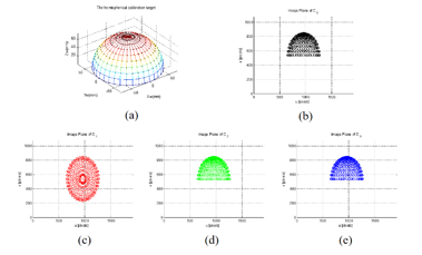
Figure 7: Simulated multi-view image
Fig. 8 shows that the Kinect camera includes a motor and color image (RGB camera in the middle). Those are include a 3D depth image (two lenses on the left and right), an infrared emitter, an infrared CMOS camera and sound (array microphone). 3D machine vision human skeleton detection results, as shown in Fig. 9. The Kinect camera defines the human skeleton joint coordinate map. This research selected Kinect camera to cost reduction. The Kinect v2 depth camera is cheap than high speed camera, and the measurement accuracy is mostly under 2 mm at 1.5 m [14]. Those condition would be meet our measurement system demonstration. The system utilizes four multi-view cameras to perform dynamic capture and record the reaction time and trajectory of the subject’s limbs, including real-time conversion of multi-view images corresponding to the 3D skeletal joint coordinate information of the human body based on references. The proposed method have been practically tested in Figure 11. In Fig. 11 is captured 3D skeletal joint of the human body with Kinect.
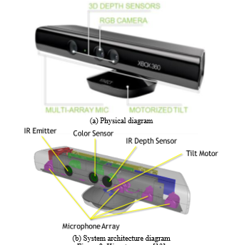
Figure 8: Kinect camera [13]
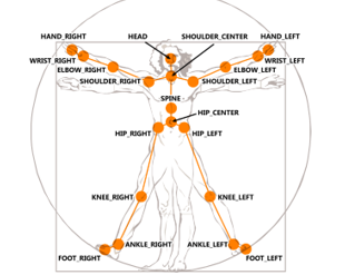
Figure 9: The Kinect camera defines the human skeleton joint coordinate map [13]
Pilot will isn’t wear any equipment in our system, which is direct collection the joints information of the human skeleton. Use Kinect to obtain the coordinates of each joint point of the human body in space. The distance formula and vector inner product formula to calculate the distance and bending angle of the human joint points. Kinect is cheap, easy to carry, and used to evaluate the reaction time of the body of the test personnel. Due to the complex movements of the subject or the influence of environmental factors, occlusion may occur. Multi-angle shooting through multiple Kinects can successfully solve such problems. The integration of information collected by multiple Kinects can reduce occlusion. Real-time measurement and on-site operation testing analysis the cockpit instruments and human body.
Fig. 10 is the “Reach to Grasp” action sequence diagram. The six human skeleton joint coordinates verify the feasibility of the human reaction time and trajectory calculation of the cockpit personnel operating the measurement tracking system. Fig. 11 illustrates captured 3D skeletal joint coordinate information of the human body with Kinect
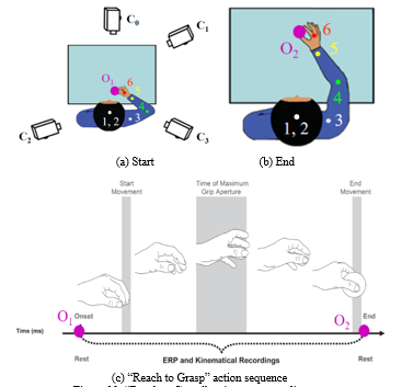
Figure 10: “Reach to Grasp” action sequence diagram
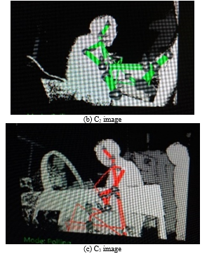
Figure 11: Captured 3D skeletal joint coordinate information of the human body with Kinect
Fig. 12 is the 3D space trajectory of pilot’s skeleton joints. Fig. 13 is the reaction time of the right arm of the pilot’s body. Among them, the action of “Reach to Grasp” moves from point O1 to point O2 at 485 ms. The starting action is within 0.4-1.4 seconds, the maximum grasping action starts, the elapsed moving time MT1: 790 ms and the highest moving speed APV1: 1165 mm/s. Finally, the moving speed of the right arm feature points #4~#6 exceeds 800 mm/s, and the rest of the head and shoulder feature points #1~#3 are almost still.
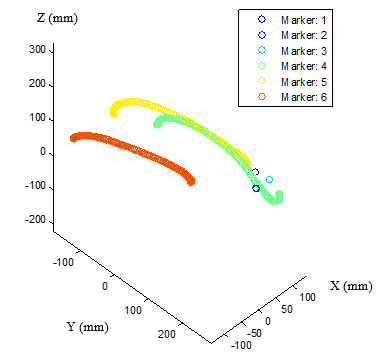
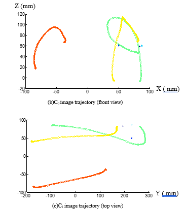
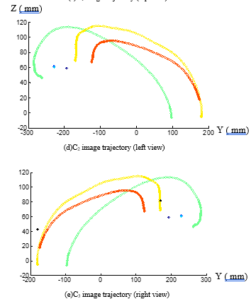
Figure 12: The 3D space trajectory of pilot’s skeleton joints
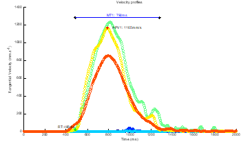
Figure 13: The reaction time of the right arm of the pilot’s body.
4. Conclusion
The study successfully proposes a measurement and tracking system for movements of the pilot’s body during flight operations. In order to overcome the limitation of image occlusion, the “Omni-directional Multi-view Image Measurement System” is used. The intersecting area can be increased by multiple cameras for 3D reconstruction. Measurement system flowchart is record skeleton detection of posture and touch area trajectory data, and then 3d data fitting with four multi-Kinect analysis. This system uses four multi-view images to eliminate the instrument and human body shielding and record the touched area. That could record the body reaction time (velocity and acceleration) and trajectory of the tested personnel. Real-time conversion of multi-view images corresponding to the 3D skeletal joint coordinate information of the human body, which measure the human-computer interaction human factors engineering integration of limb reaction time and trajectory measurement system. Finally, make prototypes, test and optimize, and achieve the research on the optimal cockpit touch area by conducting multi-view image simulation feasibility experiment framework and measurement process method. Using multiple depth-sensing cameras to perform low-cost, standardized automatic labeling of human skeleton joint dynamic capture.
Conflict of Interest
The authors declare no conflict of interest.
- Y.H. Chen, J. H. Huang, “Measurement and tracking system for movement of the pilot’s body during flight operations,” 2022 IEEE International Conference on Consumer Electronics – Taiwan, 539-540, 2022.
- E. Kruk, M.M. Reijne, “Accuracy of human motion capture systems for sport applications; state-of-the-art review”, European Journal of Sport Science, 18(6), 806-819, 2018.
- P.F. Luo, Y.J. Chao, M.A. Sutton, W. H. Peters, “Accurate measurement of three-dimensional deformations in deformable and rigid bodies using computer vision”, Experimental Mechanics, 33, 123-132, 1993.
- Y.H. Chen, Y.S. Shiao, “Control simulation and experiment of two-axis parallel kinematic mechanism”, 2016 Taiwan Power Electronics Symposium, 2006.
- C.H. Hwang, W.C. Wang, Y.H. Chen, “Camera calibration and 3D surface reconstruction for multi-camera semi-circular DIC system”, Proc. SPIE 8769, International Conference on Optics in Precision Engineering and Nanotechnology (icOPEN2013), 2013.
- MIL-STD-1333B, “Aircrew station geometry for military aircraft”, 09 JAN, 1987.
- MIL-STD-1472H, “Human Engineering”, 15 SEP, 2020.
- O. Lefrançois, N. Matton, M. Causse, “Improving airline pilots’ visual scanning and manual flight performance through training on skilled eye gaze strategies, Safety, 7(4), 2021.
- R. Li, B. Jumet, H. Ren, W. Song, ZTH Tse, “An inertial measurement unit tracking system for body movement in comparison with optical tracking”, Proceedings of the Institution of Mechanical Engineers, Part H: Journal of Engineering in Medicine, 234(7), 728-737, 2020.
- P. Biswas, “Using eye gaze controlled interfaces in automotive environments”, Springer, 2016.
- M.G. Glaholt, “Eye tracking in the cockpit: a review of the relationships between eye movements and the aviators cognitive state”, Defence Research and Development Canada Scientific Report DRDC-RDDC-2014-R153, 2014.
- E. Machida, M. Cao, T. Murao, H. Hashimoto, “Human motion tracking of mobile robot with Kinect 3D sensor”, 2012 Proceedings of SICE Annual Conference (SICE), 2207-2211, 2012.
- www.developer/microsft.com/windows/kinect/.
- G. Kurillo, E. Hemingway, M.L. Cheng, L. Cheng, “Evaluating the accuracy of the azure kinect and kinect v2,” Sensors (Basel). 22(7), 2469, 2022.