Omni-directional Multi-view Image Measurement System in the Co-sphere Framework

Adv. Sci. Technol. Eng. Syst. J. 8(2), 64–70 (2023);
 DOI: 10.25046/aj080207
This study presents an “Omnidirectional multi-view image measurement system”, which can be used to provide multi-camera 3D reconstruction and multi-view image information. Its characteristic is that four cameras take images from multiple perspectives in the co-sphere framework. The C0 is the middle camera fixed as the geometric center point of measurement, and provides a front image. The other three cameras C1~C3 provide side images, and the co-circular spheres are separated by 120 degrees to extend the circle. The arc rod adjusts the multi-angle imaging. Place the multi-view camera in the arc track and move to the specified position in the sphere to position and capture images. By changing the angle between the cameras, the range of images captured by the cameras can be changed. If the multi-view images of four cameras C0, C1, C2 and C3 are captured at the same time, a stereo camera pair can be formed by any two cameras. The stereo camera pair C0-C1, C0-C2 and C0-C3 can be compiled by using the parallax principle of left and right images matching. Finally, through the demonstration and verification of camera calibration and 3D reconstruction, it can be used for all-round multi-view image measurement.
1. Introduction
The optical measurement method has the characteristics of global, non-contact, non-destructive, high measurement accuracy and real-time measurement, and is a very important part in the field of experimental mechanics. Among them, the advantage of non-contact is that it will not cause damage to the object to be measured, and high precision and real-time measurement are very important measurement characteristics for the industry that pursues light, thin and small for research and development. Therefore, combining these advantages, Optical metrology has gradually become one of the current research focuses. The advantage of non-contact is that it will not cause damage to the object to be measured, and high precision and real-time measurement are very important. Combined these advantages, the optical quantity Measurement has gradually become one of the current research focuses. There are many optical measurement methods, such as Electronic Speckle Pattern Interferometry (ESPI), Photoelastic Method, Shadow Moiré Method and Digital Image Correlation (DIC).
When using these optical measurement methods, different cameras are usually used together with image processing technology for research and analysis. There are many stereo vision systems for 3D reconstruction applications [2-6]. For example, in [7], the author presented the 3D-DIC method with stereo vision. The combination of DIC method and 3D stereo vision, that can be applied to 3D deformation measurement and becomes the basic framework of 3D-DIC method. The 3D-DIC method is applied to the surface profile measurement research. Whether it is applied to 3D-DIC measurement or other non-contact image measurement systems, the camera structure is mostly composed of two cameras connected by a horizontal bracket. The distance and angle between them make the images overlap within a certain range. When the measurement range exceeds the visible range of the two image capture devices, only partial images of the object can be captured. The occlusion area is the camera cannot directly observe the measurement object. The camera posture must be adjusted according to the different shapes of the object, and the image capture device must be re-installed. In camera calibration procedure, the range of camera angle of view and the need for continuous calibration of the adjusted camera are application constraints. It is necessary to simplify and repeat the definition of the relationship between the coordinates of the calibration measurement system and the object to be measured.
In order to solve the visible range of the two image problems, some scholars proposed a dual-axis parallel motion mechanism with two degrees of freedom of vertical motion and horizontal motion [8]. The device uses a servo motor as a positioning control, and is mounted on a camera device, which can precisely control the camera’s imaging angle. Each servo motor of the X and Y axes operates independently, and will not become the load of another servo motor for image capture and analysis. Those three cameras to build a co-circular geometric multi-camera imaging platform system [9], connect the three cameras in series with a semi-circular measuring rod, make the optical axes of the multi-cameras co-intersect at a point in space, and the distance between the cameras. The mechanism can be used to adjust the spacing along the semi-circular measuring rod. With the superimposition feature of multiple cameras, the system can increase the range of overlapping areas of 3D reconstruction feature points and the correction parameters established inside, and simplify the complex correction procedures required for on-site measurement and reconstruction of 3D information, expanding the original 3D-DIC observation. The scope of field of view, and simplify the procedure of repeatedly defining and determining the relationship between the coordinates of the calibration measurement system and the object to be measured. According to the application of displacement and strain measurement, when observing objects of different sizes, as long as the camera distance is adjusted, it can be applied to reconstruct the three-dimensional space information of the object, and explore and increase the image data of the three-dimensional scene object in the overlapping area.
2. Research methods
The development of image measurement is bound to develop towards global, large-scale and rapid measurement. In order to meet practical purposes, multi-view images cannot be measured by only one or two cameras. It is necessary to develop an all-round multi-view image measurement system. The development of a multi-view large-scale measurement system is a very important topic. Based on this, this study proposes omnidirectional multi-camera 3D reconstruction and provide multi-view images.
In the application of 3D vision, two images taken at different positions are generally used, and the relative depth of the entire scene can be reconstructed from the 2D images. Developed 3D reconstruction products for non-contact image measurement of structural deformation. It is a system that uses two cameras to form a stereo vision measurement entity structure that can be used to measure the 3D global surface of an object. This technology uses the characteristics of the object surface as a surface comparison target to obtain 3D reconstruction measurements. When the measurement range exceeds the visible range of the two cameras, only partial images can be observed, and the area covered by the object cannot be measured.
In order to overcome the limitation of image occlusion, the “Omni-directional Multi-view Image Measurement System” with the co-sphere to solve the problem of object occlusion. The intersecting area can be increased by multiple cameras for 3D reconstruction. Provides a camera imaging device, which is convenient for shooting multiple sets of images. This device includes three arc measuring rods, so that the multi-camera circular motion can be captured by changing the movement of the multi-camera. That adjust the angle of the camera through the rotating seat. It is characterized in that multiple cameras are fixed on the arc frame, and the observation angle of the cameras is adjusted so that it has the characteristic of a co-sphere.
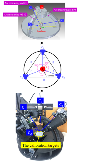
Figure 1: Omni-directional multi-view image measurement system
Figure 1 is the proposed omni-directional multi-view image measurement system. The C0 is the middle camera fixed as the geometric center point of measurement, and provides a front image. The other three cameras C1~C3 provide side images, and the co-circular spheres are separated by 120 degrees to extend the circle. The arc rod adjusts the multi-angle imaging. Place the multi-view camera in the arc track and move to the specified position in the sphere to position and capture images. By changing the angle between the cameras, the range of images captured by the cameras can be changed. If the multi-view images of four cameras C0, C1, C2 and C3 are captured at the same time, a stereo camera pair can be formed by any two cameras. The stereo camera pair C0-C1, C0-C2 and C0-C3 can be compiled by using the parallax principle of left and right images matching. Table 1 is omni-directional multi-view image measurement system specifications. Fig. 2 is four cameras captured the multi-angle images.
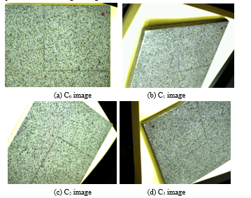
Figure 2: Four cameras captured the multi-angle images.
The internal camera calibration parameter is the camera mapping relationship between the 3D calibration target point and the 2D image point in the camera coordinate system. The external camera calibration parameter is the camera refer to the rotation and translation relationship between the world coordinate system, where the target point is located and the camera coordinate system. Camera calibration is the process of obtaining the internal and external parameters of the camera, that are defined the corresponding relationship between the three-dimensional coordinates and the image pixels through the calibration points marked on the calibration target.
Table 1: Omni-directional multi-view image measurement system specifications
| Specifications | Characteristic |
| Number of cameras | Four-camera multi-view image. The C0 is the middle camera fixed as the geometric center point of measurement, and provides a front image. The other three cameras C1~C3 provide side images, and the co-circular spheres are separated by 120 degrees to extend the circle. |
| Camera | UI-3130CP Rev. 2 – IDS Imaging Development Systems GmbH, USB 3.0, CMOS, 575.0 fps, 800 × 600, 0.48 MPix, 1/3.6″, ON Semiconductor, Global Shutter. |
| Lens | UH1220-10M, Focal Length: 12 mm, Aperture: f/2.0~C,Min. Working Distance: 10 cm, Distortion: <0.1% |
| Arc measuring rod | Three arc rods have a radius of 15 cm. |
| Measurable range | Measurable range: 3 cm × 3 cm × 3 cm (L×W×H), Minimum measurable resolution: 0.375 mm. |
| Dimension size | 40 cm × 40 cm × 40 cm (L×W×H). |
| Power | 110 V / 60 Hz. |
In [10], the author presented a two-step correction method, using radially consistent constraints, so that the correction of camera internal parameters is not affected by radial distortion. The method requires a high-cost three-dimensional high-precision calibration target. In [11], the author proposed the plane calibration method, which is uses image coordinate estimation to obtain a two-dimensional homography matrix. The internal and external parameters of the camera calibration and the radial distortion coefficient can be linearly solved. In [12], the author proposed a camera calibration method based on one-dimensional camera calibration points. This study in order to collect 360° omni-directional image information, the polar coordinate system is used. The advantage of polar coordinates is that it can describe the system directivity of the azimuth angle position of single/ multiple cameras relative to the calibration target on an image plane. In the polar coordinate system are represented by radius and angle, which are included cylindrical coordinate system and spherical coordinate system. Fig. 3 shows the spherical coordinate system and the hemispherical calibration model. A point P in the spherical coordinate system is defined by two angles φ, θ and radius r. The corresponding relationship between spherical coordinates and rectangular coordinates is as follows:
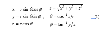
where, is the origin point. r is the radius length coordinate value, that is the distance from point P to the coordinate center. φ is the coordinate value of the azimuth angle (0≤φ≤2π), that is the counterclockwise rotation angle from the X axis. θ is the elevation angle coordinate value (0≤θ≤π), that is the upward rotation angle from the XY plane.
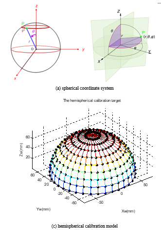
Figure 3: The spherical coordinate system and the hemispherical calibration model
3. Experimental result
Fig. 4 is the calibration targets. Fig. 4(a) is a 30mm×30mm chess plane calibration target, which is composed of 9×9 square grids intersecting micro-dots with an equidistant distance of 5mm. Figure 4(b) is a hemispherical calibration target with a radius of 15mm and a height of 15mm, which is used to verify the feasibility of 3D reconstruction of the omnidirectional multi-view measurement system. Place the calibration piece in the middle of the measurement system, move the multi-camera in the arc track to the designated position in the sphere to position and take images, and change the range of images captured by the multi-camera by changing the angle between any two cameras .
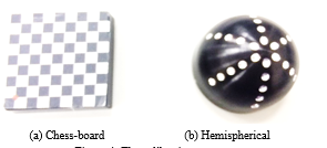
Figure 4: The calibration targets
- Omni-directional multi-camera calibration results
Calibrate each stereo pair separately using the checkerboard pattern of calibration target. To calibrated multi-camera system for stereo camera pair C0-C1, C0-C2 and C0-C3. The internal and external of multi-camera calibration parameters are showed as Table 2 and Table 3. That are respectively to find out the three-dimensional correspondence in space. Fig. 5 is the experimental result of omni-directional multi-camera calibration.
Fig. 5 (a) is the C0-C1 stereo camera as an example. The calibration parameters of the C0 and C1 single cameras are obtained respectively, and the C0-C1 stereo calibration parameters are obtained by binocular vision to find out the stereo correspondence in space. Similarly, another two sets of stereo cameras can be arranged to perform local three-dimensional reconstruction on C0-C2 and C0-C3. Finally, the multi-view cameras calibration and pose estimation are shown in Fig. 5(b).
Table 2: The internal camera calibration parameters
(a) C0-C1
| Parameter | C0 | C1 |
| Principal point (u0, v0) | 415.2, 277.1 | 403.7, 288 |
| Focal length (fx, fy) | 2593, 2593.2 | 2561.4, 2562.7 |
| Skew | 0.234 | 6.753 |
| kappa 1 | -0.038 | 0 |
(b) C0-C2
| Parameter | C0 | C2 |
| Principal point (u0, v0) | 416.5 , 271 | 410.3, 292.3 |
| Focal length (fx, fy) | 2619.5, 2619.9 | 2611.7, 2612.6 |
| Skew | -0.012 | -0.012 |
| kappa 1 | -0.043 | -0.043 |
(c) C0-C3
| Parameter | C0 | C3 |
| Principal point (u0, v0) | 415.4, 265.1 | 364.2, 270.4 |
| Focal length (fx, fy) | 2618.3, 2618.5 | 2584.9 , 2585.2 |
| Skew | 0.006 | -2.413 |
| kappa 1 | -0.041 | -0.034 |
Table 3: The external of camera calibration parameters
(a) C0-C1
| Parameter | Rotation [°] | Translation [mm] |
| X axis | 41.38 ± 0.0031 | 94.36 ± 0.64 |
| Y axis | -34.19 ± 0.0021 | 110.3 ± 0.76 |
| Z axis | -7.591 ± 0.00014 | 87.28 ± 7.5 |
| Baseline | 169.405 mm | |
(b) C0-C2
| Parameter | Rotation [°] | Translation [mm] |
| X axis | -40.67 ± 0.0026 | 107 ± 0.35 |
| Y axis | 2.595 ± 0.00042 | 60.76 ± 0.15 |
| Z axis | 118.1 ± 0.00048 | 57.3 ± 3.2 |
| Baseline | 135.734 mm | |
(c) C0-C3
| Parameter | Rotation [°] | Translation [mm] |
| X axis | 18.32 ± 0.0048 | 93.07 ± 0.53 |
| Y axis | 38.01 ± 0.0064 | 83.63 ± 0.4 |
| Z axis | -108.4 ± 0.0019 | 66.92 ± 7.8 |
| Baseline | 141.901 mm | |
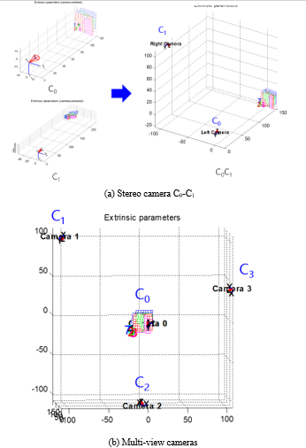
Figure 5: The experimental result of omni-directional multi-camera calibration.
This study used the IDS UI-3130CP color camera as an example to discuss the calibration and 3D reconstruction of an omni-directional multi-view image measurement system. The omni-directional multi-camera image system is used to analyze the simulated omni-directional multi-camera image. Fig. 6 is IDS UI-3130CP color camera. Table 4 is IDS UI-3130CP color camera specifications. According to the optical design parameters of the measurement system: The image resolution is 800×600 pixels. The chip size of the image sensor is 4.8 µm×4.8 µm with a 12mm 1:2.0 1/1.8” lens. The best working distance is 15cm, and the simulation results can be measured within the working range of 3cm×3cm×3cm (L×W×H).
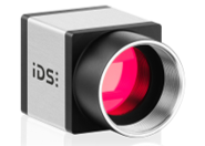
Figure 6: IDS UI-3130CP color camera
Table 4. IDS UI-3130CP color camera specifications
| Name | UI-3130CP Rev. 2 |
| Family | CP |
| Interface | USB 3.0 |
| Sensor type | CMOS |
| Manufacturer | ON Semiconductor |
| Frame rate | 396 fps |
| Resolution (h×v) | 800×600 pixels |
| Optical Area | 3.84 mm×2.88 mm |
| Shutter | Global Shutter |
| Optical class | 1/3.6″ |
| Resolution | 0.48 MPix |
| Pixel size | 4.8 µm×4.8 µm |
Figure 7 is the simulated the setup of omni-directional multi-view measurement with four cameras. Fig. 8 is the simulated four cameras captured multi-view image. Four-camera multi-view image. The C0 is the middle camera fixed as the geometric center point of measurement and provides a front image, is showed as Fig. 8(a). The other three cameras C1~C3 provide side images and the co-circular spheres are separated by 120 degrees to extend the circle, is showed as Fig. 8(b)-(d).
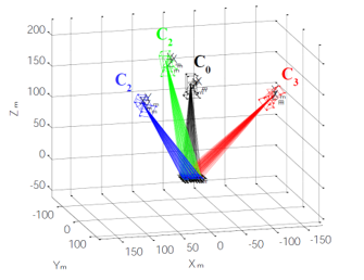
Figure 7: Simulated the setup of omni-directional multi-view measurement with four cameras
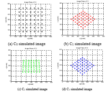
Figure 8: Simulated four cameras captured multi-view image
- Omni-directional multi-view 3D reconstruction results
The hemispherical calibration target is a radius of 15mm and a height of 15mm in the middle of the omnidirectional multi-view camera. The multi-view images of four cameras C0, C1, C2, and C3 through any two cameras to form a stereo camera pair. Using the principle of parallax matching of the left and right images, the stereo camera pair C0-C1, C0-C2, and C0-C3 can be compiled performs three-dimensional reconstruction of each part. We used the hemispherical calibration target for the omnidirectional 3D reconstruction. Fig. 9 is the omni-directional original multi-view images. Fig. 10 is the omni-directional multi-view of 3D reconstruction for hemispherical calibration target.
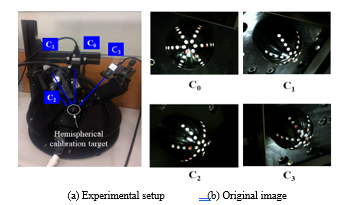
Figure 9: The omni-directional original multi-view images
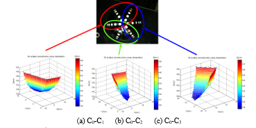
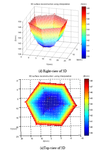
Figure 10: The omni-directional multi-view of 3D reconstruction for hemispherical calibration target
4. Conclusion
This research successfully developed an “omnidirectional multi-angle image measurement system”. Any camera can move along the arc measuring rod to a designated position within the sphere to position and capture images. The three local 3D reconstructions of C0-C1, C0-C2, and C0-C3 are performed through the arrangement of stereo cameras, and the same position superposition calculation is performed, and the optimal 3D reconstruction calculation is performed using the ICP (Iterative Closest Point) iterative closest point algorithm. Finally, the 3D reconstruction experiment results of the 14.8 mm-high semicircular sphere calibration piece were obtained, and the measurement error was 1.3%. With the current best measurement working distance is 15 cm, the multi-angle imaging optical imaging analysis has been completed the measurement range of 3cm×3cm×3cm to 0.375 mm resolution.
Conflict of Interest
The authors declare no conflict of interest.
- Y.H. Chen, J.H. Huang, “Calibration and 3D reconstruction of omni-directional multi-view image measurement system,” 2022 IEEE International Conference on Consumer Electronics – Taiwan, 591-592, 2022.
- D. Murray, J.J. Little, “Using real-time stereo vision for mobile robot navigation,” Autonomous Robots, 8(2), 161-171, 2000.
- N.G. Oh, J.I. Cho, K. Park, “On performance enhancement of a following tracker using stereo vision,” ICCAS 2010, 1259-1262, 2010.
- E. Dandil, K.K. ÇEVİK, “Computer vision based distance meaurement system using stereo camera view,” 3rd International Symposium on Multidisciplinary Studies and Innovative Technologies (ISMSIT), 1-4, 2019.
- J. Liu, J. Pan, N. Bansal, C. Cai, Q. Yan, X. Huang, Y. Xu., “PlaneMVS: 3D plane reconstruction from multi-view stereo,” In IEEE Conference on Computer Vision and Pattern Recognition (CVPR), 2022.
- Z. Yang, Z. Ren, Q. Shan, Q. Huang, “MVS2D: Efficient multiview stereo via attention-driven 2D convolutions,” Computer Vision and Pattern Recognition (or CVPR) 2022.
- P.F. Luo, Y.J. Chao, M.A. Sutton, W. H. Peters, “Accurate measurement of three-dimensional deformations in deformable and rigid bodies using computer vision”, Experimental Mechanics, 33, 123-132, 1993.
- Y.H. Chen, Y.S. Shiao, “Two axis independent parallel manipulators of control and stereo vision matching”, Journal of Industrial Education and Technology, 33, 137-148, 2008.
- C.H. Hwang, W.C. Wang, Y.H. Chen, “Camera calibration and 3D surface reconstruction for multi-camera semi-circular DIC system”, International Conference on Optics in Precision Engineering and Nanotechnology (icOPEN2013), 8769, 123-132, 2013.
- R. Y. Tsai, “A versatile camera calibration technique for high-accuracy 3D machine vision metrology using off-the-shelf TV cameras and lenses,” IEEE Journal of Robotics and Automation, 3(4), 323-344, 1987.
- Z. Zhang, “A flexible new technique for camera calibration,” IEEE Transactions on Pattern Analysis and Machine Intelligence, 22(11), 1330-1334, 2000.
- Z. Zhang, “Camera calibration with one-dimensional objects,” IEEE Transactions on Pattern Analysis and Machine Intelligence, 26(7), 892- 899, 2004.