Temperature-Compensated Overcharge Protection Measurement Technology

Adv. Sci. Technol. Eng. Syst. J. 8(2), 24–29 (2023);
 DOI: 10.25046/aj080203
Recently, many problems have been caused by battery fires. The existing BMS(Battery Managment System) measured the voltage of each cell of the battery through the physical connection between the battery and the control module. However, if a battery with up to 1000 VDC becomes inoperable due to an external factor, the battery is damaged, and accordingly, a large current of the battery breaks the control unit of the BMS with 5 VDC to 24 VDC, putting the BMS inoperable. If the battery is operated when the bms is in trouble, it poses a risk of battery fire.Recently, as bms technology was announced with a wireless function, battery information could be easily transferred from the outside, so that convenience was maximized, but stability is still weak. This paper physically separated the battery and control module by measuring the battery voltage depending on the strength of the LED by connecting the battery and LED. and furthermore, the measurement error should be less than 1 mV even when the temperature changes. In addition, it was designed to operate at a low output level of 200 μW to 360 μW using the sub-threshold section of the LED.
1. Introduction
Recently, with the development of battery technology, it is widely used in the field of electric vehicles, such as Uninterruptible Power Supply (UPS) & Energy Storage System (ESS), etc., demand for a system using lithium-ion batteries has increased rapidly. Accordingly, the demand for battery management system (BMS), which has a function of controlling and protecting a battery, is increasing [1]. However, as battery fires have recently occurred, many issues have been raised. As a result of the analysis of electric vehicle fire accidents in 2018, about 16 accidents were reported. Fire accidents involving electric vehicles occur during a collision, but they occur during charging, driving, and even parking. Therefore, this study proposes a system to identify the main causes of electric vehicle fire and prevent fire accidents. The battery fire is caused by various factor (same, lack of choice words), such as temperature and humidity of the surrounding environment, battery fire caused by overcharging, etc. [2]. However, most of the causes are that the overvoltage of the battery affects the control unit that uses a low voltage, which destroys the control unit, and accordingly, the control unit cannot react with it, leading to a battery fire. As a representative function of BMS, it monitors the voltage between cells of the battery to support an overcharge protection function and safely performs charging and discharging through battery cell balancing. However, it is reported that the control unit is destroyed due to an imbalance between a battery capable of representing 1,000 VDC or higher and a control unit operating between 1.2 V and 2.4 V, and a fire accident of battery is ensued due to BMS failure. As a fundamental solution, a new BMS system that supports the safe operation of the overcharge protection monitoring system by isolating the high voltage battery and the control module is proposed. The overcharge protection system of the existing battery system is shown in Figure 1. In the structure of Figure 1, for voltage measurement, switch 1 is closed to charge C1, switch 1 is opened, switch 2 is closed to charge C2, and the control unit is ADC(Analog to Digital Converter) and measured with C2 voltage [3]. In this measurement method, when a problem of a high voltage unit including a battery pack occurs, insulation is destroyed in a low voltage unit. Therefore, like the existing BMS, a circuit that monitors the battery voltage without physically connecting the control unit and the battery pack is required. This study applied an indirect measurement technology that measures the voltage without the physical connection between the control part and the battery pack. A circuit that monitors the voltage between battery cells while separating the high voltage and low voltage parts was proposed and implemented using this technology. Systems with detachable structures have some cases mentioned in existing communication circuits [4]. There is also a patent for monitoring voltage by applying a photo sensor, but it was not a technology used for isolation structures [5]. This study proposes and implements an isolated battery cell monitoring system by applying LEDs and photo sensors.
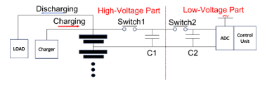
Figure 1: Existing Overcharge Monitoring Circuit [6]
2. Overcharge protection device design
2.1. Battery cell Indirect monitoring
In this paper, an indirect measurement technology of measuring the voltage through a medium without physical connection between a battery pack including a high voltage unit and a control unit is proposed and implemented. Indirect measurement technology is a technology that measures a change in the voltage of a battery by detecting a change in the brightness of an LED. To this end, the light of the LED was prevented from being emitted through the light blocker, and the light was measured using a photo sensor. A block diagram of indirect measurement technology is shown in Figure 2.
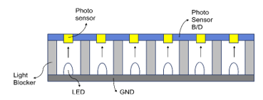
Figure 2: Block diagram of indirect measurement technology [7]
Normally, lithium-ion batteries are known to have an operating range of 3V to 4.3V. However, to measure a voltage using the indirect measurement technology in this paper, an alternative is required because the operating voltage is not matched with the lithium-ion battery. Therefore, this paper proposes an indirect measurement technology that uses a diode array to drop the voltage of the battery and measures the voltage through the corresponding change in the brightness of the LED. Figure 3 shows an indirect measurement circuit.
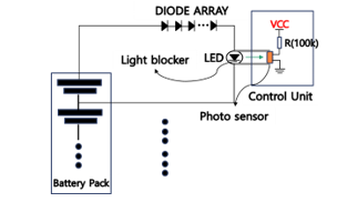
Figure 3: Indirect measurement circuit [7-8]
According to the structure shown in Figure 3, the LED connected to the battery is transmitted to the photo sensor through the light block. The resistance value of the photo sensor changes according to the brightness of light. It is connected to the VCC to measure the voltage applied to both ends of the photo sensor. Since the indirect measurement technology proposed in this paper measures the voltage using a medium, the brightness value of the existing LED is measured and stored in a memory included in the control unit. The voltage is estimated by comparing the brightness value stored in the memory with the currently measured brightness value.
2.2. Isolated LED & Photo sensor characteristics
2.2.1. Sensing characteristics for LED
The indirect battery voltage measurement method proposed in this paper measures the brightness of an LED whose brightness changes depending on battery voltage using an illuminance sensor called Cadmium sulfide (CdS). The resistance of CdS varies with the intensity of brightness. Therefore, the voltage at both ends of CdS is generated through the VCC connected to the front end of CdS, and the voltage is measured through the Analog to Digital Converter (ADC) according to the change in the resistance of CdS. In this paper, the resistance change of CdS measured through ADC is defined as Brightness. Figure 4 shows the graph of the relationship between the battery voltage and brightness measured at room temperature.
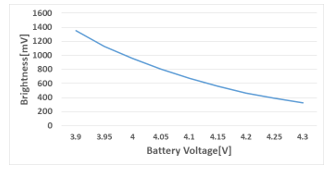
Figure 4: Relationship between Battery Voltage and Brightness
In the graph shown in Fig. 4, it can be found that the relationship between battery voltage and brightness has an inversely proportional relationship. The lithium-ion polymer used for the test in this paper has an operating range of 3.9V to 4.3V. Therefore, it can be confirmed that Brightness has an operation part of 1.3V to 0.3V from 3.9V to 4.3V, which are battery operation parts. In this paper, the voltage was estimated using the aforementioned relationship between the battery voltage and Brightens.
2.2.2 Light source wavelength
The peak spectral response of CdS used in this paper is between 500 nm and 600 nm. Therefore, it is necessary to adjust the spectrum band of the LED used to the spectrum band of the Cds used in this paper. Graphs of the spectrum band of CdS used in this paper and the spectrum band according to the color of LEDs are shown in Figures 5 and 6, respectively.
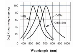
Figure 5: Spectrum band of the CdS [9]
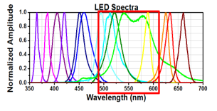
Figure 6: Color of LED according to wavelength [10]
In the graph in Figure 5, it can be seen that the wavelength of CdS is the most sensitive in the characteristics of about 500 nm to 600 nm. On the other hand, the red square box of the relationship between the wavelength length of the LED and the color of the LED in Figure 6 represents LEDs in the wavelength band of 500 nm to 600 nm, which is the wavelength of CdS. The LEDs in the red square box are green LED, blue LED, and yellow LED. Therefore, the LEDs suitable for the wavelength band of CdS, the photo sensor used in this paper, can be said to be Green, Yellow, and Blue LEDs. However, the indirect measurement technology in this paper is a circuit for cell monitoring of batteries, so it shall be possible to accurately measure the battery voltage. On the other hand, the intensity of light in an LED is determined by the current flowing through the LED. Therefore, the circuit including the LED should show a difference in current consumption that can be recognized according to the battery voltage.
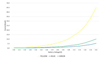
Figure 7: Current consumption according to the LED color
The current consumption graph of each LED is shown in Figure 7. Figure 7 shows the graph of measuring current by connecting 6 diodes of a diode array with LEDs in series. As shown in the figure above, it can be seen that the current of the Blue LED is 0.3㎂ ~ 5.4㎂, Green LED is 0.3㎂ ~ 10.2㎂, Yellow LED is 0.7㎂ ~ 45.2㎂ in the 3V to 4.5V Voltage range. Therefore it was confirmed that th Blue LED were not suitable for use in the indirect measurement circuit of this paper.
2.3. Low power behavior design
Since the battery voltage measurement technology operates using battery power, high power consumption leads to degradation of battery performance. Therefore, there is a need for a method to reduce power consumption due to the characteristics of indirect measurement technology that constitute a closed circuit at all times. Therefore, this paper proposes to use the sub-threshold section of LED as an operation section to reduce power consumption of indirect measurement technology. The motion graph of the sub-threshold is shown in Figure 8.
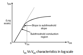
Figure 8: V-I characteristics of LEDs
The structure illustrated in Fig. 8 shows that a leakage current is generated even when a voltage smaller than an operating voltage is applied in a section operated at a point lower than the threshold voltage. The brightness of the light of the LED is proportional to the current and there is a current characteristic curve that changes according to the applied voltage. The general LED usage section is after the operating voltage, and current consumption is high in this section. However, it was confirmed that leakage current occurred even in a low voltage section of 0.7 V or less, and thus current consumption was low and LED was emitting light. It is a known technology in the field of transistor and is being used as a technology called sub-threshold swing. A recent study is also being conducted on the analysis of low-power CMOS inverters using sub-threshold swing [11]. This paper measured the voltage by adjusting the number of diode arrays and lowering the operating range of LEDs to the sub-threshold region. Figure 9 shows the voltage applied to the LEDs according to the number of diodes and the threshold voltage of the LEDs.
The LED used in this paper is the Yellow LED, and the wavelength is 590 nm. Therefore, as shown in Figure 9, the threshold voltage of the LED is about 1.75V to 1.97V [10]. If the voltage of the LED exceeds the threshold voltage, the current rises rapidly, so it should be designed so that the voltage does not exceed the threshold voltage in all sections. Therefore, in this paper, the number of diode arrays was selected and designed so that it does not exceed the Threshold Voltage in all sections, as shown in the structure of the graph in Figure 9.
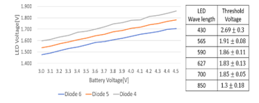
Figure 9: Voltage of the LED according to the number of diodes & Threshold Voltage of LED [12]
2.4. Temperature compensation
In a universal electronic circuit, the intensity of the current consumed by the elements of the circuit varies with temperature. Therefore, the indirect measurement circuit proposed in this paper also changes the current consumed according to the temperature. On the other hand, LED is a device in which the intensity of light changes according to the intensity of current consumed, so the value of brightness changes according to temperature. The change in Brightness according to temperature is shown in Figure 10.
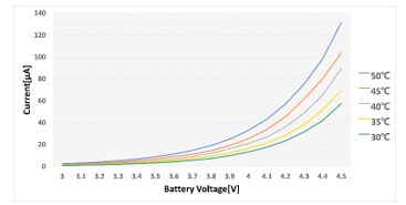
Figure 10: Brightness change according to temperature change of LED
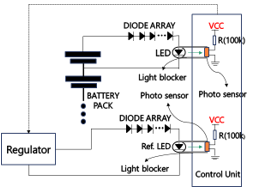
Figure 11. Temperature compensation circuit [8]
The graph illustrated in Fig. 10 shows that the difference in brightness at the same battery voltage at a low temperature and low voltage tends to be large. Therefore, an appropriate temperature compensation circuit is required. This paper measured a temperature corresponding to brightness by connecting a circuit, such as an indirect measurement circuit, with a regulator, and implemented a temperature compensation circuit by applying an offset to the brightness of each LED. The temperature compensation circuit of this paper is shown in Figure 11.
In the circuit shown in Figure 11, a regulator is the power supply that generates the corresponding voltage regardless of external factors, such as temperature, humidity, etc. Therefore, the Ref connected to the regulator. The LED emits corresponding light regardless of external factors. Measure the light using the photo sensor included in the control unit and estimate the temperature using the look-up table stored in the memory included in the control unit. The look-up table is schematized and shown in Figure 12.
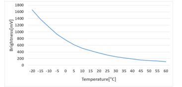
Figure 12: Change of Ref. LED’s Brightness
2.5. Structure of Light blocker
With the indirect measurement technology proposed in this paper, it is very important to have a system that estimates a battery voltage by measuring the intensity of light of an LED according to a change in the battery voltage. In this paper, it is defined as a light blocker, a structure that prevents LED light from being emitted. The designed light blocker is shown in Figure 13.
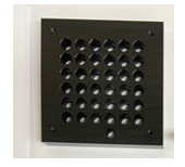
Figure 13: Light blocker
The light blocker in Figure 13 is a structure designed to monitor 36 battery cells. Therefore, it is designed as a structure that can absorb light well so that it does not affect brightness measured according to external light. The light blocker is used in conjunction with the designed Printed Circuit Board (PCB) and can be secured to the PCB through a hole located at the apex of the light blocker. Therefore, it is possible to design so that light does not fade out.
3. Result & Measurement
3.1. Structure of the designed overcharge protection device
Indirect measurement systems are sensitive to the influence of external light. Therefore, it is important to solve structurally so that external light does not affect the indirect measurement system. Therefore, in this paper, the external influence was greatly reduced by designing the PCB of the system in a multilayer structure. The structure of the designed PCB is shown in Figure 14.
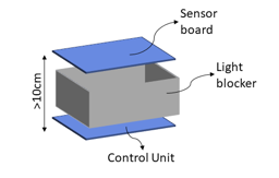
Figure 14: Structure of the designed PCB
In the structure illustrated in Fig. 15, the distance between the sensor board and the control unit was designed to be 10cm or less, so that the light of LED could be transmitted intact, and a size of PCB was designed to be small through the multilayer structure.
3.2. Measurement of overcharge protection device
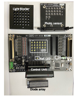
Figure 15: Designed Board
The designed indirect measurement system is shown in Figure 15. The structure of Figure 15 is 36 LEDs installed in the control unit and 1 Ref. It is a system configured by combining a light blocker on an LED to block light, a photo sensor substrate on it, and a diode array substrate to a control unit. The board shown in Figure 16 is designed to measure the voltage of a total of 36 battery cells. The memory included in the control unit stores a lookup table for the brightness and voltage of the LED.
Table 1 shows the average of the values measured more than 10 times by applying a voltage from 3.9V to 4.3V to the LED channel of the designed board. It has an error value of 1 mV at a temperature change of -20°C to 60°C and the electric power amount is about 200 μW to about 360 μW.
Table 1: Results of Overcharge protection board
| Battery Voltage[V] | Measured Voltage[V] | Power[㎼] | Current[㎂] |
| 3.919 | 3.918 | 211.905 | 54.067 |
| 3.971 | 3.970 | 219.975 | 55.400 |
| 4.022 | 4.021 | 231.112 | 57.467 |
| 4.071 | 4.070 | 244.936 | 60.033 |
| 4.103 | 4.102 | 254.523 | 62.033 |
| 4.174 | 4.172 | 282.696 | 67.733 |
| 4.204 | 4.203 | 398.204 | 70.933 |
| 4.272 | 4.271 | 341.333 | 79.900 |
| 4.290 | 4.289 | 355.669 | 82.900 |
In addition, the comparison results with other papers are shown in Table 2. [4] In the case of , it is not a voltage measurement method used in BMS, but an electric line. Although it is a different application field, voltage measurement technologies in the form of isolation are compared. [13] In the case of , voltage measurement was carried out without physical connection using a wireless transceiver, and the indirect measurement method proposed in this paper measured the voltage using the brightness of light of an LED.
Table 2: Results of comparison with other papers
| Paper | Error | Power | temp | Physical connection |
| [4] | -40~30[mV] | – | -20~40[℃] | O |
| [13] | 5[%] | – | – | X |
| This work | 1[mV] | 200~350[㎼] | -20~60[℃] | X |
4. Conclusion
This paper proposes and implements an indirect measurement technology that measures voltage without physical connection between battery pack and control unit. Recently, BMS functions for safe battery use have been emphasized [14]. However, it was announced in 2022 as representative of Infineon’s BMS (TLE9012DQU) and TI’s wireless BMS (BQ79616-Q1), a group that presents advanced BMS technology. Infineon announced wired BMS technology, while TI and Linear Technology implemented wireless capabilities in BMS. The above technologies and this proposed technology are compared and analyzed and shown in the Table 3.
Table 3: Results of comparison with other BMS technology
| No | Factor | Infineon BMS (TLE9012DQU) [15] | TI BMS (BQ79616-Q1) [16] | This work | Remark | |
| Characteristics | Explanation | |||||
| 1 | Physical isolation of high and low voltage parts | Wired connection | Wired connection | Complete physical isolation | Safed Isolated BMS Operation | Advantage |
| 2 | Communication interface with the master board | Wired serial
communication |
Wireless communication | Wired serial
communication |
Ease of data delivery | Disadvantage |
| 3 | Battery power consumption | 20mW | 20mW + wireless comm | 200~350 [uW] | Low power operation | Advantage |
As shown in the Table 3, the existing wireless technology maximizes convenience by providing wireless communication function to the battery so that battery information can be easily received wirelessly from the outside, but it is not implemented as a solution to a battery accident. However, the BMS technology proposed in this proposal is an original technology with a completely different isolation structure and has the advantage of minimizing battery consumption through safe battery operation and low power consumption operation of BMS while implementing BMS. The implemented system can measure the voltage of a total of 36 battery cells, and the voltage used is greatly reduced using the sub-threshold section. It was verified that the voltage measurement error was 1mV or less and the power amount was approximately 200μW to 360μW. In addition, a solution to the error according to temperature was presented using the LED, which is the reference point. Therefore, it can be confirmed that the technology proposed in this paper can have a safe battery monitoring system based on a complete isolation structure and a low power operating structure at the same time.
Conflict of Interest
The authors declare no conflict of interest.
Acknowledgment
This work was supported by a Korea Evaluation Institute of Industrial Technology (KEIT) grant funded by the Korean government (MOTIE) (No. 20022473, Development of 5KWh High-Safety Expandable Battery Module for Electric Vans and Electric Utility Cart)
- “Battery Management System,” https://www.innopolis.or.kr/board/view?linkId=44443&menuId=MENU00999, INNOPOLIS, 2020.03.27
- D. Guo, Lei Sun, “The Causes of Fire Explosion of Lithium Ion Battery for Energy Storage,” 2018 2nd IEEE Conference on Energy Internet and Energy System Intergration(EI2), Oct. 2018
- T. Yue, Liji Wu, ”High-precision voltage measurement IP core for battery management SOC of electric vehicles,” 2014 12th IEEE International Conference on Solid-State and Integrated Circuit Technology(ICSICT), Oct. 2014
- A. Hande, S.Kamalasadan, A.Srivastava, ”A Selective Voltage Measurement System for Series Connected Battery Packs,” Proceeding of the IEEE SoutheastCon 2006, May 2006
- D.I. Kim, J.I. Kim “Battery management system,” Korean Patent Office,10-2019-0055524, 2021.04.29.
- M.Lelie, T.Braun, M. Knips, H.Nordmann, F.Ringbeck, H.Zappen, D.U Sauer, “Battery Management System Hardware Concepts: An Overview,“ Appl. Sci 534, 2018, 8,
- J.W. Noh, S.H. Ahn, H.S Kang, J.U. Yeon “Voltage Measurement Method, Voltage Measurement Device, and Battery System,” Korean Patent Office, 10-2020-0111200, 2020.09.01.
- JinUk Yeon, KunSik Kim, Innyeal Oh,”Temperature-compensated Overcharge protection Indirect measurement circuit,” 2022 Thirteenth International Conference on Ubiquitous and Future Networks(ICUFN),2022.07
- TOKEN, “CDS LIGHT-DEPENDENT,“ wep-site,PGM5 CDS Phtoresistors, 2010
- Michael W. Davidson, “Fundamentals of Light-Emitting Diodes (LEDs),” Carl Zeiss Microscopy Online Campus,
- R Sindhu, Shilpa Mehta, “Sub-threshold Inverter for Low Power Consumption,” 2018 Second International Conference on Inventive Communication and Computational Technologies(ICICCT), Apr. 2018.
- Francesca Santonocito, Antonio Tornabene, Dominique Persano-Adorno, “From led light signboards to the Planck’s constant,” 2018 Journal of Physics Conference Series, Sept 2018
- Xuemin Zhang, Bin Yue, Jian Huang, Yuchuan Ruan, Peng Zhang, “Reserch on Non-contact Voltage Measurement Technology,” 2019 IEEE 2nd International Conference on Automation, Electronics and Electrical Engineering(AUTEEE), Nov. 2019
- K. W. See, Guofa Wang, Yong Zhang, Yunpeng Wang, Lingyu Meng, Xinyu Gu, Neng Zhang, K. C. Lim, L. Zhao & Bin Xie, “Critical review and functional safety of a battery management system for large-scale lithium-ion battery pack technologies,” International Journal of Coal Science & Technology volume 9, 2022.05
- Infineon, “TLE9012DQU, Li-Ion battery monitoring and balancing IC,” Infineon web-site, 2022.02.18
- Texas Instruments, “BQ79616-Q1”,16-S automotive precision battery monitor, balancer and integrated protector with ASIL-D compliance,” Texas Instrumnets web-site, 2022.09