Nonlinear Model Predictive Control of Rover Robotics System

Adv. Sci. Technol. Eng. Syst. J. 8(1), 44–56 (2023);
 DOI: 10.25046/aj080106
The paper presents two robust and efficient control algorithms based on (i) Optimal Control Allocation (OCA) and (ii) Nonlinear Model Predictive Control (NMPC). The robotics system consists of two rovers with mecanum wheels and mounted two 7-DOF arms carrying a common load. The overall system is an underdetermined one with non-holonomic constraints. The developed control algorithms focus on providing an optimal solution to the wheel and joint torque saturation problem, which is typically encountered while manipulating a large and heavy payload. The first control algorithm based on OCA minimizes a quadratic cost function consisting of robot joint and rover wheel torques, contact forces, and moments using only the current state values and the system dynamics. It is computationally very efficient. The NMPC algorithm minimizes a quadratic cost function which not only includes the current states but also the future state estimates, and the control inputs over a specified prediction horizon. The system consisting of multi-rover with a dual arm is highly non-linear. The linear MPC technique on which most of the previous studies relied is not adequate. On the other hand, the computational difficulties of a generic NMPC algorithm is remarkably high. In this paper, an elegant, discretized technique with exact realization is implemented to take into account the full non-linear model and yet provide a simple real-time solution satisfying a minimum performance index subject to constraints. The results show that the developed control algorithms OCA and NMPC work efficiently, and the minimum the contact moments and forces, and the joint torques are realized while two arms carry a common load and successfully track a reference end-effector trajectory. The results also indicate that although NMPC algorithm is computationally more involved, it provides superior results in reducing joint and wheel torques as well as contact moments and forces.
1. Introduction
This paper is an extension of the work originally presented in IEMTRONICS [1]. The Optimal Control Allocation algorithm (OCA) presented in the original work is further extended to accommodate a Nonlinear Model Predictive Control technique to increase performance of the approach.
There has been a significant interest in exploring complex environments using mobile rovers. Such rovers are commonly used in space exploration, construction, mining, and military.
Especially, there has been a considerable amount of interest in Space Robotics Exploration missions in the last two decades. Similar to on-orbit robotics missions (e.g., servicing, assembly, and manufacturing), the future planetary exploration missions will also include tasks such as assembly of large space structures using multiple coordinating rovers and the rover-mounted robotics manipulators. Recently the Moon and Mars rover missions are the main target of various space agencies including NASA, Canadian Space Agency, ESA, JAXA, etc. Most of these space agencies in collaboration with space industries and research centers are heavily focusing on innovative rover technologies and designs. Autonomous rover motion control capability has been identified as one of the critical and enabling technology requirement for such systems. Although, there is a significant amount of research studies in the fields of control of single rover trajectory and force control of fixed-based arms, there are still major research challenges in the areas of load sharing multi- rovers and arms, particularly, real-time force and motion control when they are carrying a common load.
The initial technological challenges that involved designing a mobile rover were related to its mechanics. These included the development of dynamic control systems and collision free trajectories.
In order to develop effective control systems for mobile rovers, a team led by Necsulescu [2,3] studied the free and contact motion of the vehicles. They also developed methods to generate collision free trajectories and perform force control.
Motion control of rovers with nonholonomic constraints were studied using differential wheeled rovers in [4,5] These constraints exist if the constraints cannot be expressed in the form of time derivatives of a function consists of the generalized coordinates.
There have been extensive studies in control of systems with non-holonomic constraints. However, most of the cases, kinematic control is typically achieved by ignoring the dynamics when dealing with systems with non-holonomic constraints [6]. However, it has been shown that a mechanical system with these constraints were controlled in spite of its structure [7]. In addition, it has been shown that a non-holonomic system cannot be brought to a single equilibrium with a smooth time-invariant feedback [8].
In a study conducted in Kalaycioglu [9], a control technique with optimal force distribution for multiple robotic manipulators was demonstrated. However, it only involved two cooperating arms and did not include rovers.
The use of a Model Predictive Control (MPC) framework facilitates the optimization of a given performance index. It also allows for the analysis of the system constraints and dynamics [10–15]. One of the most challenging aspects of implementing a robust model of (MPC) is dealing with the various uncertainties that can impact its performance [16]. Due to the characteristics of the model’s receding horizon, standard MPC can provide an adequate level of robustness [17].
Unfortunately, the literature has shown that standard MPC cannot provide an adequate performance in complex robotics systems [18]. To address this issue, various research studies have been conducted to develop novel MPC methods that can provide a robust and stable performance [19–23].
The scope and capabilities of Non-linear Model Predictive Control (NMPC) have significantly improved over the past few years. Due to the increasing number of tools that can be used to implement this type of model, the performance of this algorithm has been greatly improved. Some of these include the ability to perform fast gradient use and input parameterisation [24–27]. The application of NMPS for free-floating space manipulator are provided in [28–31].
The mechanics of wheeled locomotion have also attracted a lot of attention [32–37][. A number of studies have been conducted on the dynamics and kinematics of the mecanum wheel (a subcategory of omnidirectional wheel) [38–43].
There has been a significant amount of research on the various aspects of wheeled locomotion, but it is still not yet feasible to fully understand the mechanisms involved in the movement control of multiple rovers and mounted arms. For instance, the development of systems with multi- rovers with dual manipulators that can perform real-time trajectories while manipulating a common load is still in its early stages.
This paper presents two robust and efficient control algorithms based on (i) Optimal Control Allocation (OCA) and (ii) Nonlinear Model Predictive Control (NMPC) for a rover robotics system with mecanum wheels when the two 7-DOF arms operating a common load. The system is an underdetermined one subject to non-holonomic constraints. The control algorithms focus on providing an optimal solution to the wheel and joint torque saturation problem, which is typically encountered while manipulating a large and heavy payload.
The first control algorithm based on OCA minimizes a quadratic cost function (a performance index) consisting of robot joint and rover wheel torques, contact forces, and moments using only the current state values and the system dynamics. It is computationally very efficient. The NMPC algorithm minimizes a quadratic cost function which not only includes the current states but also the future state estimates, and the control inputs over a specified prediction horizon.
The literature on the application of MPC for robotics is mainly focused on linear models. However, the multi-rover dual arm coordinating system is highly non-linear and MPC lacks robust applications in this area. In this paper, we present a novel NMPC discretized technique that incorporates the full non-linear characteristics of the multi-rover dual arm system.
This paper consists of four sections. The first section provides the mathematical formulations such as the kinematics and dynamics models of the total system including two n-degree redundant manipulators, two rovers and a common load. The second section presents two novel control algorithms based on optimal control allocation (OCA) and non-linear model predictive control (NMPC) which are formulated to minimize the wheel moments, the joint torques, and contact moments/forces. The third section provides the simulation results and discussion, and the fourth section provides some concluding remarks and recommendations for future work.
2. Theoretical Formulations
2.1. The Rover Robotics System
The system includes two mobile rovers with four mecanum wheels and two n-DOF redundant arms attached on the two rovers carrying a common load. Figure 1 shows an example of such a system with two rovers and two n-degree arms.
Table 1 contains the rover and robotics parameters utilized in the computer simulations.. The rotation angle ψi and the position vector , provide the pose of the center of mass Ci of the ith rover-in the inertial coordinate system, X, Y, Z. The coordinate axes xci , yci , zci attached to point Ci are obtained via a rotation around Z-axis with an angle of ψi.
The masses associated with the rovers and the wheels are given as mci and mwij, respectively for the ith rover and the jth wheel, , j=1…4 and i=1,2 for each rover. The distances between the wheel centers along the yci and xci-axes are denoted by 2a and 2b, respectively.
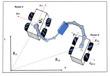
Figure 1: Description of the rover robotics system
The wheels have a radius of s and the angle of rotation, and the angular rate are denoted as and, respectively. The rollers are attached to the outer rims of the mecanum wheels as illustrated in Figure 1. The angle βij is defined as the angle between the axis of rotation of the roller and the xci of the jth wheel of the ith rover.
2.2. Model of Kinematics
, the velocity vector of the center of the jth wheel of the ith rover can be determined by the following relationship:
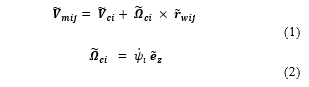
where is the velocity of the mass center of the rover, is the angular velocity vector of the rover and is a unit vector both along the zci, – axis while is the position vector from the rover’s mass center to the wheel center.
The velocity vector , representing the velocity of a point P located at the roller center can be expressed as
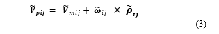
where is the position vector from the wheel’s center to the point P, the roller center.
If the rollers do not slip, does not have a component in the direction of the axis of roller rotation , and can be expressed as
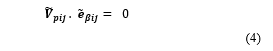
where is a unit vector along the roller’s axis of rotation. After carrying out some algebraic manipulations using (3) and (4), one can write the following expressions:
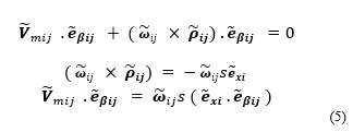
where s is the radius of the wheel and is a unit vector in the direction of the xci – axis.
Furthermore, rewriting the equations of constraints by utilizing (1) and (5), one can obtain the following relationships:
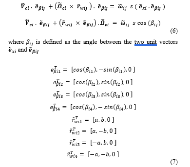
One can obtain the following expressions by plugging (7) into (6) and substituting 45o for :
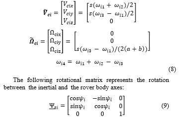
Homogeneous transformation matrix which transforms the coordinates between frame-g and frame-f on the robot arm can be obtained by Denavit-Hartenberg (D-H) convention as follows.
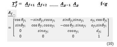
where , are the parameters related to joint-f and link-f on the ith arm, namely is the offset, is the fth link-length , is the joint angle and is the twist as defined in DH convention.
The following expressions can be used to obtain the Jacobian matrices and the first-time derivatives of these matrices associated with the rover’s center and any arbitrary point-k on the arm:
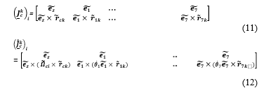
Where is the unit vector along the ith joint rotation axis, is the unit vector along , and are the position vectors from ith joint and the rover’s center to the point k, respectively.
The linear and angular velocities and accelerations of point k on the ith rover arm can be calculated as follows:
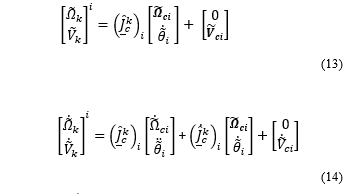
where is a vector consisting of the angular and linear velocity vectors of the point k on the ith arm, respectively while is a vector consists of the ith rover-arm joint angular rates.
2.3. Model of Dynamics
The dynamics equations of motions of the system is derived using the Lagrangian formulation. The total kinetic energy Tt consists of two parts, the rotational and translational kinetic energies of the robotics arms and the rovers.
The angular and translational velocities of the rovers as well as that of the robot links’ center of mass can be calculated using (14) and (8). Then, the total kinetic energy of the system can be obtained using (15).
The dynamics equations of motion can be obtained using the following Lagrangian formulation:
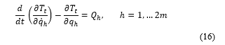
and m=(n+3), n represents the total number of degrees of freedom of the robotics arms.
Applying (16), the dynamics equations of motions for both rovers and the arms can be written in the following form:
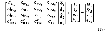
where is the mass / inertia matrix (a positive definite matrix) and, , , are the wheels’ angular accelerations for the two rovers i=L and R, and , are the joint rotational accelerations for the two manipulators, i=L and R, respectively. The indices L and R are referred to the first and second rover and robotics arm, respectively.
The non-linear Coriolis and centrifugal terms are represented by , and and are the joint control torques for the two robot manipulators. Finally, are the wheel control moments for the two rovers.
includes the wheels angular rates of the ith rover, i=L and R for two rovers. If there is no slip, the fourth wheel angular rate can be calculated using (8).
2.4. Optimal Control Allocation (OCA) Technique
The robotics system composed of two rovers and two redundant arms is an undetermined because of the excessive number of sensors and actuators used to control the motions of the links and rovers.
A novel two-stage optimal control technique is derived in this section and the control system block diagram is provided in Figure 2a.
The first stage of the diagram generates the reference trajectories for the end-effectors corresponding to a given payload trajectory. The Impedance control equations representing this first stage are provided in (18). These equations are developed in [2].
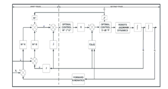
Figure 2: a. Optimal control system block diagram – Two Stage Control
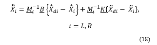
where, , are 6×6 positive definite matrices and are chosen in accordance with the tracking performance requirements. . (i varies between L and R for each arm) are the end-effector trajectories while .correspond to the reference trajectories of the attachment points on the common load.
The expressions for and as follows:
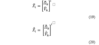
where k point is the end-effector for the ith arm. Performing the least-square minimization of joint rates, the inverse kinematics of the robotics system can be solved as the following:
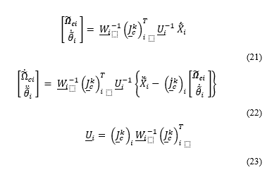
where is a square positive definite weighting matrix with the dimensions of (n+3) by (n+3).
The second stage in the block diagram is predicated on optimal control allocation (OCA). The mathematical model is provided below.
The performance index (a cost function) C is formulated to minimize the wheel moments and the joint torques , and the contact moments and forces and applied by the end-effectors on the common load
The performance index C can be expressed as:

is a (2n+18, 2n+18) positive definite weighting matrix, is the ((2n+12), 1) Lagrangian multiplier and vector includes the equations of constraints and can be calculated as shown in (26).
The vector contains the contact forces / moments, the wheel moments as well as the joint torques for the two arms and rovers as described below:
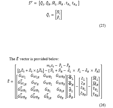
where are the translational acceleration and the mass of the common load, respectively and. , , is the position vector measured from the ith arm’s contact point to the load’s mass center, while and are the angular rate and the inertia matrix of the common load around its center of mass.
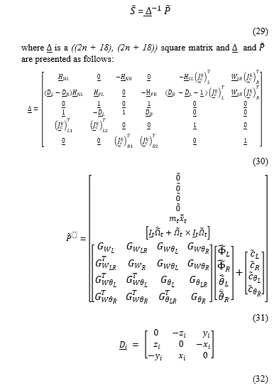
Once can minimize the performance index C by taking the derivative of C with respect to and to obtain the minimum norm of wheel moments, joint torques, as well as the contact moments /force exerted by the end-effectors on the common load.
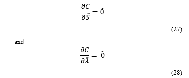
One can obtain the minimum norm of containing the wheel moments, joint torques, as well as the contact force and moments by making use of the equations (27) and (28).
2.5. Non-linear Model Predictive Control (NMPC) Technique
The control block diagram of the NMPC is illustrated in Figure.2b. It replaces the second stage of the model in Figure.2a. The reference trajectory shown in this diagram is the output of the first stage, i.e., the impedance control trajectory generation. However, in this case, the future state estimates are also taken into account to estimate the future reference trajectory values.
A robust NMPC algorithm is implemented by optimizing a performance index of the system which considers the predictions of the output signal and the constraints on the states, outputs and inputs as illustrated in Figure 2b.
The main difference between the Optimal Control Allocation (OCA) and the Non-linear Model Predictive Control (NMPC) is that the latter utilizes a model to predict and control future behavior, while the former only takes into account the current and the past.
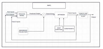
Figure 2: b Nonlinear Model Predictive Control (NMPC) block diagram
The optimization process carried out through the NMPC algorithm is performed at each control interval to predict the system’s future behavior. It involves implementing various optimization problems related to the cost functions and constraints. The cost function is a type of scalar which needs to be minimized at intervals to assess the system’s performance.
Besides the cost functions, the system also has to perform under various constraints to check its performance. These include the plant output and states. The modified states are adjusted depending on the constraints that are applied to the system.
The conventional MPC formulation for the multi-rover nonlinear system can be written as:
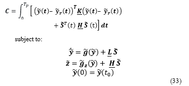
where is the prediction horizon; and are (2(2n+6) x 2(2n+6)) and ((2n+18) x (2n+18)) positive definite square weighting matrices, respectively; are part of the nonlinear system equations.
Also, , is a (1 x 2(6+2n)) state vector, vector is previously defined in Eq.(16), and is the reference / desired states.
The non-linear system can now be described with an exact quasi linear parameter varying realization:
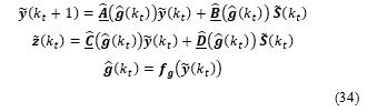
where is the sampling instant and is a vector of the measured outputs at instant .
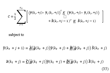
The NMPC is employed at each sampling instant .and the discrete states and control inputs are obtained minimizing the following performance index i.e., the Cost Function:
3. Computer Simulation Results and Discussion
The results of the computer simulations and their discussions are presented in this section. First, a prescribed trajectory for the common payload’s center mass is generated. Then, the desired (reference) trajectories for the two end-effectors are obtained using a method known as the impedance control technique (shown as the first stage in the block diagram).
The goal of the simulation is to obtain the minimum joint and rover wheel torques and contact forces while simultaneously tracking the desired end-effector pose using the developed two different control algorithms (i) OCA and (ii) NMPC.
The parameters for the robotic arms and the rovers employed in the computer simulations are presented in Table 1. A mini version of the SSRMS is utilized.
Table 1: The System Parameters Utilized in the Computer Simulation
| Description of Hardware Configuration Items | Dimensions (m) | Mass (kg) |
| Rovers-(#1 and #2) | (0.5×0.5×0.3) | 40 |
| Common Load | (0.4x1x0.4) | 10 |
| Link #1 | (0.1×0.1×0.1) | 1 |
| Link #2 | (0.1×0.1×0.1) | 1 |
| Link #3 | (1×0.1×0.1) | 3 |
| Link #4 | (1×0.1×0.1) | 5 |
| Link #5 | (0.1×0.1×0.1) | 3 |
| Link #6 | (0.1×0.1×0.1) | 1 |
| Link #7 | (1×0.1×0.1) | 3 |
The desired trajectories for the rotational and translational motions of the common load are presented with time in Figure 3.
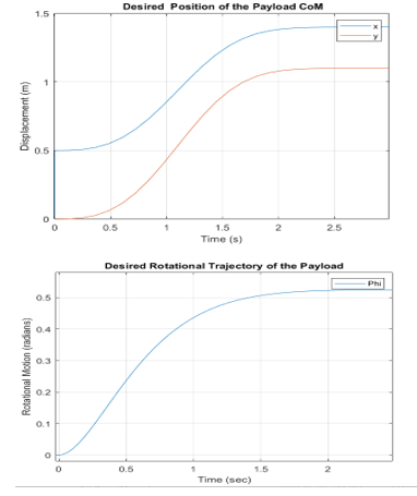
Figure 3: Variation of the reference trajectory for the common load
The minimum norm of the contact moments /forces, the joint torques, as well as the control forces and moments on Rovers 1 and 2 are plotted in Figure 4a-m using OCA and NMPC algorithms. The non-optimum joint torques (in blue), the joint torques realized by application of OCA algorithm (in red) and by NMPC algorithm (in yellow) are plotted for comparison purposes. The comparison of the plots illustrates that the NMPC is superior and then followed by OCA.
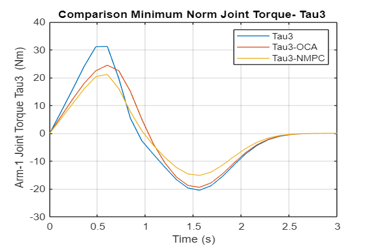
Figure 4: a Variation of the Joint 3 Torque obtained by Non-optimal, OCA, NMPC Algorithms (Arm 1)
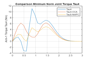
Figure 4: b-Variation of the Joint 4 Torque obtained by Non-optimal, OCA, NMPC Algorithms (Arm 1)
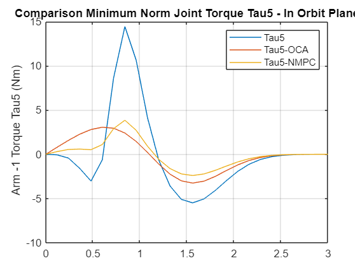
Figure 4: c Variation of the Joint 5 Torque obtained by Non-optimal, OCA, NMPC Algorithms (Arm 1)
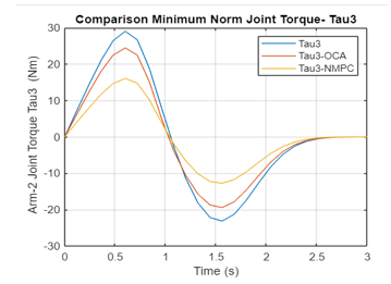
Figure 4: d Variation of the Joint 3 Torque obtained by Non-optimal, OCA, NMPC Algorithms (Arm 2)
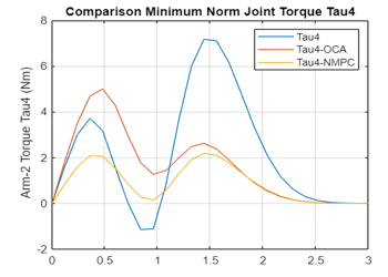
Figure 4: e Variation of the Joint 4 Torque obtained by Non-optimal, OCA, NMPC Algorithms (Arm 2)
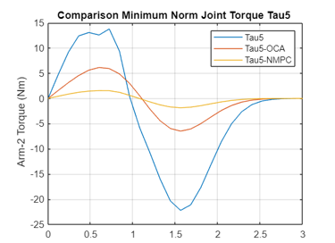
Figure 4: f Variation of the Joint 5 Torque obtained by Non-optimal, OCA, NMPC Algorithms (Arm 2)
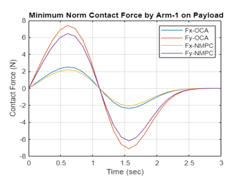
Figure 4: g Variation of the Contact Forces on Payload by Non-optimal, OCA, NMPC Algorithms (Arm 1)
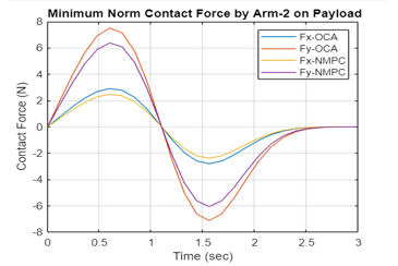
Figure 4: h Variation of the Contact Forces on Payload by Non-optimal, OCA, NMPC Algorithms (Arm 2)
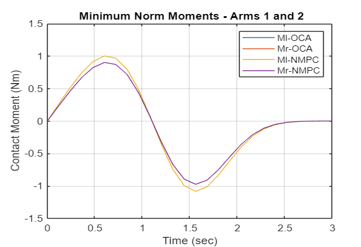
Figure 4: i Variation of the Contact Moments on Payload by Non-optimal, OCA, NMPC Algorithms (Arms 1 and 2)
Again, the NMPC is superior to OCA in obtaining minimum contact moments / forces applied to the common load while the two end-effectors are carrying a common load.
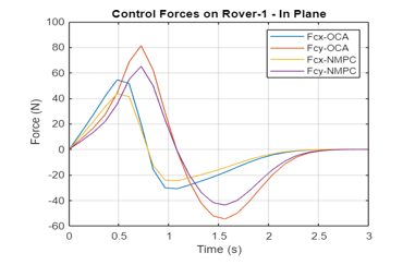
Figure 4j Variation of the Control Forces on Rover 1 by Non-optimal, OCA, NMPC Algorithms (Rover 1)
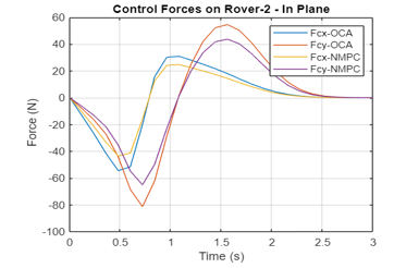
Figure 4k Variation of the Control Forces on Rover 2 by Non-optimal, OCA, NMPC Algorithms (Rover 2)
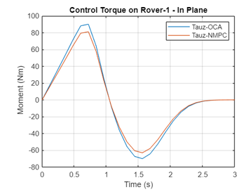
Figure 4l Variation of the Control Moment on Rover 1 by Non-optimal, OCA, NMPC Algorithms (Rover 1)
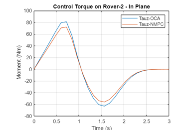
Figure 4m Variation of the Control Moment on Rover 2 by Non-optimal, OCA, NMPC Algorithms (Rover 2)
A comparative analysis shows that again NMCP is superior to OCA in obtaining minimum norm of control moments and forces for Rovers 1 and 2.
The time variations of joint angular accelerations are shown in Figure 5.
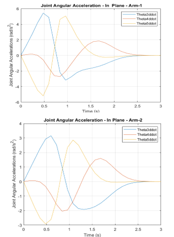
Figure 5 Variation of joint angular accelerations for the first and second arm
The joint accelerations are integrated to calculate rotational rates and angles using (13) and are presented in Figure 6.
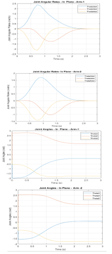
Figure 6: Variation of joint angular rates and angles for the first and second arm
The trajectories of the point C, the center of mass of the two rovers are determined by (22) and (8) and are shown in Figure 7.
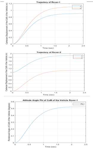
Figure 7 Variation of Rover 1 and 2 positions and orientations with time
The wheel angles of the two rovers are calculated utilizing (22) and are presented in Figure 8.
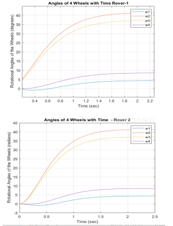
Figure 8 Variation of angles of rotations for rover wheels – rovers 1 and 2
Conclusions and Future Work
The paper presented two novel control algorithms for motion and force control of a multi-rover robotics system when the two end-effectors carrying a common load. One algorithm is predicated on Optimal Control Allocation (OCA) and the other is a discretized (ii) Nonlinear Model Predictive Control (NMPC) algorithm.
The paper focused on developing robust and computationally efficient real-time control algorithms that can minimize the performance index consisting of the norm of the rovers control moments / forces, the joint torques, , as well as the contact moments / forces applied to the common load by two end-effectors.
The norm of wheel moments, joint torques, and the contact moments and forces were minimized to resolve the torque / moment saturation problem often seen while carrying a common load. The paper also presented a minimum norm solution for an underdetermined system subject to non-holonomic constraints Moreover, the developed control algorithm also provided a real-time capability of trajectory for both the rovers and the arms while carrying a common load.
The system consisting of multi-rover with a dual arm was highly non-linear. The linear MPC technique on which most of the previous studies relied was not adequate. On the other hand, the computational complexity of a generic NMPC algorithm was very demanding. Therefore, in this paper, an elegant discretized technique with exact realization was implemented to take into account the full non-linear model and yet provide a simple real-time solution satisfying a minimum performance index subject to constraints.
The results of the computer simulations illustrated that the two algorithms OCA and NMPC worked efficiently. They were able to realize the minimum contact forces and moments and rover wheel moments and forces, joint torques, while manipulating a common load and tracking a reference load trajectory. In addition, the minimal norm solution also satisfied the non-holonomic constraints.
The results revealed that the optimization scheme used by the NMPC algorithm was the most effective when it came to achieving the lowest joint torques and forces. It was then followed by the OCA algorithm and the conventional least square method, respectively.
The authors are currently working on a research project to build a testbed to experimentally validate the computer simulation results. The comparisons of experimental and simulation results will be part of the future research work. Furthermore, the authors assumed no slippage occurred. However, the maximum driving force of each wheel is limited by the dynamic friction coefficient and the magnitude of the normal force acting on it. If this is exceeded, this assumption will no longer be valid. The normal forces will be incorporated in the dynamics model for the future work.
Conflict of Interest
The authors declare no conflict of interest.
- S. Kalaycioglu, A. de Ruiter, “Coordinated Motion and Force Control of Multi-Rover Robotics System with Mecanum Wheels,” in 2022 IEEE International IOT, Electronics and Mechatronics Conference (IEMTRONICS), IEEE: 1–9, 2022, doi:10.1109/IEMTRONICS55184.2022.9795804.
- D.S. Necsulescu, B. Kim, S. Kalaycioglu, FREE MOTION, COLLISION AVOIDANCE AND CONTACT MOTION CONTROL FOR MOBILE ROBOTS, Elsevier: 223–228, 1993, doi:10.1016/B978-0-08-041897-1.50042-0.
- N. Necsulescu, B. Kim, S. Kalaycioglu, “Contact motion control for mobile robots,” in 7th IFAC Symposium on Information Control Problems, IFAC, Toronto, 1992.
- R. Fierro, F.L. Lewis, “Control of a nonholonomic mobile robot: backstepping kinematics into dynamics,” in Proceedings of 1995 34th IEEE Conference on Decision and Control, IEEE: 3805–3810, doi:10.1109/CDC.1995.479190.
- Yu Tian, N. Sidek, N. Sarkar, “Modeling and control of a nonholonomic Wheeled Mobile Robot with wheel slip dynamics,” in 2009 IEEE Symposium on Computational Intelligence in Control and Automation, IEEE: 7–14, 2009, doi:10.1109/CICA.2009.4982776.
- Y.H. Amengonu, Y.P. Kakad, “Dynamics and control for Constrained Multibody Systems modeled with Maggi’s equation: Application to Differential Mobile Robots Partll,” IOP Conference Series: Materials Science and Engineering, 65, 012018, 2014, doi:10.1088/1757-899X/65/1/012018.
- G. Campion, B. d’Andrea-Novel, G. Bastin, Controllability and state feedback stabilizability of non holonomic mechanical systems, Springer-Verlag, Berlin/Heidelberg: 106–124, doi:10.1007/BFb0039268.
- A.M. Bloch, N.H. McClamroch, “Control of mechanical systems with classical nonholonomic constraints,” in Proceedings of the 28th IEEE Conference on Decision and Control, IEEE: 201–205, doi:10.1109/CDC.1989.70103.
- S. Kalaycioglu, “Control of multiple robot manipulators with optimal force distribution,” in IEEE Canadian Conference on Electrical and Computer Engineering, 1991.
- M. Vukov, S. Gros, G. Horn, G. Frison, K. Geebelen, J.B. Jørgensen, J. Swevers, M. Diehl, “Real-time nonlinear MPC and MHE for a large-scale mechatronic application,” Control Engineering Practice, 45, 64–78, 2015, doi:10.1016/j.conengprac.2015.08.012.
- J.B. Rawlings, “Tutorial overview of model predictive control,” IEEE Control Systems, 20(3), 38–52, 2000, doi:10.1109/37.845037.
- Y. Shi, K. Zhang, “Advanced model predictive control framework for autonomous intelligent mechatronic systems: A tutorial overview and perspectives,” Annual Reviews in Control, 52, 170–196, 2021, doi:10.1016/j.arcontrol.2021.10.008.
- P.D. Christofides, R. Scattolini, D. Muñoz de la Peña, J. Liu, “Distributed model predictive control: A tutorial review and future research directions,” Computers & Chemical Engineering, 51, 21–41, 2013, doi:10.1016/j.compchemeng.2012.05.011.
- M. Ellis, H. Durand, P.D. Christofides, “A tutorial review of economic model predictive control methods,” Journal of Process Control, 24(8), 1156–1178, 2014, doi:10.1016/j.jprocont.2014.03.010.
- F. Michael, Implementation of Linear Model Predictive Control –Tutorial, 2021.
- S. Yu, M. Reble, H. Chen, F. Allgöwer, “Inherent Robustness Properties of Quasi-infinite Horizon MPC,” IFAC Proceedings Volumes, 44(1), 179–184, 2011, doi:10.3182/20110828-6-IT-1002.01969.
- H. Wei, C. Shen, Y. Shi, “Distributed Lyapunov-Based Model Predictive Formation Tracking Control for Autonomous Underwater Vehicles Subject to Disturbances,” IEEE Transactions on Systems, Man, and Cybernetics: Systems, 51(8), 5198–5208, 2021, doi:10.1109/TSMC.2019.2946127.
- H. Wei, Q. Sun, J. Chen, Y. Shi, “Robust distributed model predictive platooning control for heterogeneous autonomous surface vehicles,” Control Engineering Practice, 107, 104655, 2021, doi:10.1016/j.conengprac.2020.104655.
- K. Zhang, Q. Sun, Y. Shi, “Trajectory Tracking Control of Autonomous Ground Vehicles Using Adaptive Learning MPC,” IEEE Transactions on Neural Networks and Learning Systems, 32(12), 5554–5564, 2021, doi:10.1109/TNNLS.2020.3048305.
- Y. Zou, X. Su, S. Li, Y. Niu, D. Li, “Event-triggered distributed predictive control for asynchronous coordination of multi-agent systems,” Automatica, 99, 92–98, 2019, doi:10.1016/j.automatica.2018.10.019.
- K. Zhang, Y. Shi, “Adaptive model predictive control for a class of constrained linear systems with parametric uncertainties,” Automatica, 117, 108974, 2020, doi:10.1016/j.automatica.2020.108974.
- J.S. Ladoiye, D.S. Necsulescu, J. Sasiadek, “Force Control of Surgical Robot with Time Delay using Model Predictive Control,” in Proceedings of the 15th International Conference on Informatics in Control, Automation and Robotics, SCITEPRESS – Science and Technology Publications: 202–210, 2018, doi:10.5220/0006908602020210.
- R.A. Gangapersaud, G. Liu, A.H.J. de Ruiter, “Detumbling of a non-cooperative target with unknown inertial parameters using a space robot,” Advances in Space Research, 63(12), 3900–3915, 2019, doi:10.1016/j.asr.2019.03.002.
- T. Englert, A. Völz, F. Mesmer, S. Rhein, K. Graichen, “A software framework for embedded nonlinear model predictive control using a gradient-based augmented Lagrangian approach (GRAMPC),” Optimization and Engineering, 20(3), 769–809, 2019, doi:10.1007/s11081-018-9417-2.
- K. Rathai, Synthesis and Real-time Implementation of Parameterized NMPC Schemes for Automotive Semi-active Suspension Systems, PhD Thesis, Communaut´e Universit´e Grenoble Alpes, Grenoble, 2020.
- R. Quirynen, M. Vukov, M. Zanon, M. Diehl, “Autogenerating microsecond solvers for nonlinear MPC: A tutorial using ACADO integrators,” Optimal Control Applications and Methods, 36(5), 685–704, 2015, doi:10.1002/oca.2152.
- F. Aghili, “Optimal control of a space manipulator for detumbling of a target satellite,” in IEEE Int. Conf. Robot. Automatica, IEEE, 2009.
- T. Rybus, J. Seweryn, J. Sasiadek, “Application of predictive control for manipulator mounted on a satellite,” Archives of Control Sciences, 28(1), 105–118, 2018.
- M. Wang, J. Luo, U. Walter, “A non-linear model predictive controller with obstacle avoidance for a space robot,” Advances in Space Research, 57(8), 1737–1746, 2016, doi:10.1016/j.asr.2015.06.012.
- M. Morato, J. Normey-Rico, O. Sename, “Model Predictive Control Design for Linear Parameter Varying Systems: A Survey,” in Annual Reviews in Control, 64–80, 2020.
- E. Psomiadis, E. Papadopoulos, “Model-Based/Model Predictive Control Design for Free Floating Space Manipulator Systems,” in 2022 30th Mediterranean Conference on Control and Automation (MED), IEEE: 847–852, 2022, doi:10.1109/MED54222.2022.9837196.
- M. Wada, S. Mori, “Holonomic and omnidirectional vehicle with conventional tires,” in Proceedings of IEEE International Conference on Robotics and Automation, IEEE: 3671–3676, doi:10.1109/ROBOT.1996.509272.
- J. Ostrowski, J. Burdick, “The Geometric Mechanics of Undulatory Robotic Locomotion,” The International Journal of Robotics Research, 17(7), 683–701, 1998, doi:10.1177/027836499801700701.
- C. Stöger, A. Müller, H. Gattringer, Parameter Identification and Model-Based Control of Redundantly Actuated, Non-holonomic, Omnidirectional Vehicles, 207–229, 2018, doi:10.1007/978-3-319-55011-4_11.
- P.F. Muir, C.P. Neuman, “Kinematic modeling of wheeled mobile robots,” Journal of Robotic Systems, 4(2), 281–340, 1987, doi:10.1002/rob.4620040209.
- F.G. Pin, S.M. Killough, “A new family of omnidirectional and holonomic wheeled platforms for mobile robots,” IEEE Transactions on Robotics and Automation, 10(4), 480–489, 1994, doi:10.1109/70.313098.
- G. Campion, G. Bastin, B. D’Andrea-Novel, “Structural properties and classification of kinematic and dynamic models of wheeled mobile robots,” in [1993] Proceedings IEEE International Conference on Robotics and Automation, IEEE Comput. Soc. Press: 462–469, doi:10.1109/ROBOT.1993.292023.
- G. Wampfler, M. Salecker, J. Wittenburg, “Kinematics, Dynamics, and Control of Omnidirectional Vehicles with Mecanum Wheels,” Mechanics of Structures and Machines, 17(2), 165–177, 1989, doi:10.1080/15397738909412814.
- A. Gfrerrer, “Geometry and kinematics of the Mecanum wheel,” Computer Aided Geometric Design, 25(9), 784–791, 2008, doi:10.1016/j.cagd.2008.07.008.
- L.-C. Lin, H.-Y. Shih, “Modeling and Adaptive Control of an Omni-Mecanum-Wheeled Robot,” Intelligent Control and Automation, 04(02), 166–179, 2013, doi:10.4236/ica.2013.42021.
- A. Shimada, S. Yajima, P. Viboonchaicheep, K. Samura, “Mecanum-wheel vehicle systems based on position corrective control,” in 31st Annual Conference of IEEE Industrial Electronics Society, 2005. IECON 2005., IEEE: 6 pp., 2005, doi:10.1109/IECON.2005.1569224.
- Y. Wang, D. Chang, “Motion performance analysis and layout selection for motion system with four Mecanum wheels,” Journal of Mechanical Engineering, 45(5), 307–316, 2009.
- M.O. Tatar, C. Popovici, D. Mandru, I. Ardelean, A. Plesa, “Design and development of an autonomous omni-directional mobile robot with Mecanum wheels,” in 2014 IEEE International Conference on Automation, Quality and Testing, Robotics, IEEE: 1–6, 2014, doi:10.1109/AQTR.2014.6857869.