Design of an Open Source Anthropomorphic Robotic Hand for Telepresence Robot

Adv. Sci. Technol. Eng. Syst. J. 8(1), 17–29 (2023);
 DOI: 10.25046/aj080103
Most anthropomorphic robotic hands use a lot of actuators to imitate the number of joints and the movement of the human hand. As a result, the forearm of the robot hand has a large size for the installation of all actuators. This robot hand is designed to reduce the number of actuators, but also retain the number of movable joints like a human hand by using the four-bar linkage mechanism and only flexion-extension movements. This stamen is added in the problem statement according to the reviewer’s comment. The special features of this robotic hand are the ability to adjust the link length and the range of rotation for each joint to suit various applications and can fabricate with 3D printing and standard parts with costing about $750. All hardware CAD files and equations are published on the GitHub website, which benefits for researchers to utilize as an open-source approach that their project might be further expanded in the future. The anthropomorphic robotic hand has five fingers, 16 joints, and 12 active Degrees of Freedom (DOFs) with 12 servo motors applied to finger motion and one for wrist motion. The structure of the hand is designed using the average of Asian human hands in combination with the golden ratio. All servo motors are installed in the forearm designed in a ventilated structure with 12V vent exhaust fan motor to stabilize the operating temperature of the robotic hand. Size and weight of the hand included with the forearm are 20×54×16.5 centimeters and 2.2 kilograms respectively. The hand has achieved human-like movement by using a four-bar linkage mechanism and tendon with PTFE tube to guide operation path of the tendon with the lowest friction force. This paper presents the design processes, the experimental set-up, and the evaluation of the finger movements. From the experiment of grasping objects, this hand was able to grasp 10 basic grasp types including 32 different objects, perform 9 common gestures, and lift the object to 450 grams. From this paper, the kinematic equation is proved that the designed finger structure can move exactly as the equation with maximum error of repeatability test around 1.6 degrees.
1. Introduction
This paper is an extended paper of our work initially presented in 2021 4th International Conference on Robot Systems (ICRSA 2021) [1]. The technology that the operator interacts with the robot remotely is called the telepresence robot. This technology allows the human remotely to control the robotic end effector system in a human environment with experience as they locate there. In order to elaborate the sensibility of the operator, the design should be similar in structure and scale to the human. One of the main systems of the telepresence robot is an anthropomorphic robotic hand enabling a user to interact with the remote environment realistically.
The human hand is one of the best grippers in the world which can interact with and perceive the physical environment. However, the anatomy of the human hand is complicated to be implemented in robotics field due to size, proportions and mechanisms. For example, each person has a different size and length of each finger according to their genes [2]. The focus of this paper lies in the average hand size of Asian people, which is similar to Thai people. Thus, this paper using the average hand size of Koreans (167 males) and the Golden ratio [3-5] to design robotic hands.
Generally, the robotic hand is numerous in the design in terms of the number-type of actuator, active hand DOFs, total hand joints, power transmission, sensors, and price. The price of each robot hand varies. The cost of robotic hands has ranged between $1,500 and $150,000, depends on the number and type of actuator, sensor, and application programming interface (API) [6]. In addition, most robotic hands measure only grasping and performing various gestures, but this paper has added the repeatability experiments of robotic hands and the accuracy verification of the equations provided in the conference paper.
In this article, we designed an anthropomorphic robotic hand based on the anatomical structure that use the kinematic equation to calculate the length of the four-bar linkage ( ) of four common fingers. Before that, the designer must define basics of the configuration, including the range of motion of each joint ( ), and initial degrees ( ) as shown in Table 1 and Figure 1. Since the average Korean hand size informed the total length of each finger, a golden ratio is required to devided the average length to each phalanx ( ). The purpose of this paper is to design a new open-source robotic hand with a low cost ($750) by using standard parts and 3D printing techniques and publish it on the GitHub website. Moreover, the performances of the design of low-cost robot hand are high performance from the tested as shown in the experiment section. The performances of this hand are proven from five experiments: grasping experiment, gesture experiment, motor temperature experiment, structure experiment, and repeatability experiment.

Figure 1: The Simplified Image of Finger and Parameters
Table 1: Parameter of Equations
| Proximal joint | ROM of | ||
| Middle joint | ROM of | ||
| Distal joint | ROM of | ||
| Proximal phalanx | Distance of | ||
| Middle phalanx | Distance of | ||
| Distal phalanx | Initial degree of | ||
| Inner link1 | Initial degree of |
2. Design
In fact, each joint of the human hand can move in two directions: flexion-extension and abduction-adduction. The flexion-extension movement is increase or decrease the angle between the bones of the limb at a joint while the abduction-adduction motion is away or toward the midline of the body as shown in Figure 2.
In this article, the anthropomorphic robotic right hand is 200 mm wide, 225 mm long and the forearm is 145 mm wide, 315 mm long. The robot hand contains four common fingers (differs in length of each joint), thumb, palm, wrist, forearm, and skin of fingertips as shown in Figure 3. All fingers were designed for only flexion-extension movement. The wrist part has only one actuated joint, the thumb has three actuated joints, and the other fingers have two actuated joints per finger. Figure 2 depicts the MCP, PIP, and DIP joints on each finger, excluding the thumb. All actuated joints use a cable with PTFE tube to control a position, and the underactuated joint uses a linkage mechanism to drive the DIP joint movement that relates to the PIP joint. All servo motors are installed in the forearm designed in a ventilated structure with a 12V 4000rpm exhaust fan. The total weight is about 2.2 kilograms.
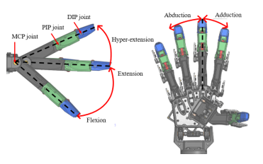
Figure 2: The Finger Movement
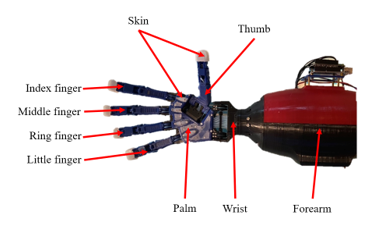
Figure 3: The Robot Hand with Forearm and Skin
2.1. Finger Design
This finger is a development from the finger published in the conference ICRSA 2021. Previously, tendons were routed inside robot fingers to protect tendons from the external environment, such as objects that are caught or touched that can damage the tendon. From Figure 4 (a), the distance and degree of pulling the tendons are not constant when compared with Figure 4 (b).
Because the inner finger has a very tiny space, the radius of the tendon for pulling the joints of the finger was less. To tighten the grip, the tendons used to transmit the force are shifted to the outside near the screw attachment to keep the degrees and pull distance of tendons constant throughout the operation, as shown in Figure 4. Inside the finger, there is a cavity for routing the tendon to the internal finger before attaching the PIP joint of the finger. Since each joint has a shaft, tendons are unable to pass directly through the MCP joint. This design is enabling the tendons to pass as close as possible to the MCP joint to have the least moment of force caused by the pulling of PIP joint, and PTFE tubes can be inserted to reduce the friction force in pulling the tendons as shown in Figure 5.
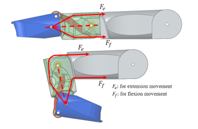
Figure 4 (a): The Index Finger and Routing Tendon Inside the Finger
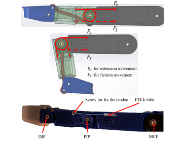
Figure 4 (b): The Index Finger with Tendon Routing Outside and Fingertip’s Skin
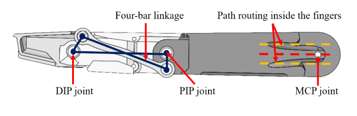
Figure 5: The Four-bar Linkage Mechanism and Path Routing in the Finger
Because the average size of the Korean hand only defines the length of each finger, the golden ratio is required to calculate the length of each phalanx. The distal phalanx of each finger is very small of different lengths (21.15 mm, 22.01 mm, 21.08 mm, 18.45 mm), making it unable to be installed with a four-bar linkage mechanism. This problem can be solved by using an equal length of each distal phalanx. The length of distal phalanx that can be achieved is 21.37 mm. Each finger’s length and range of motion are uniformly designed, as shown in Tables 2, 3, and Figure 6 respectively.
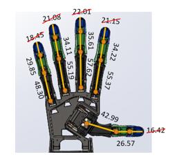
Figure 6: The Length of Each Phalanx
Table 2: Length of Each Phalanx [mm.]
| No. | Name | Length (mm.) |
| 1 | Distal phalanx-all fingers | 21.37 |
| 2 | Middle Phalanx-Index | 34.22 |
| 3 | Middle Phalanx-Middle | 35.61 |
| 4 | Middle Phalanx-Ring | 34.11 |
| 5 | Middle Phalanx-little | 29.85 |
| 6 | Proximal Phalanx-Thumb | 26.57 |
| 7 | Proximal Phalanx-Index | 55.37 |
| 8 | Proximal Phalanx-Middle | 57.62 |
| 9 | Proximal Phalanx-Ring | 55.19 |
| 10 | Proximal Phalanx-little | 48.30 |
| 11 | Metacarpal Phalanx-Thumb | 42.99 |
| 12 | Distal phalanx wide-all fingers | 18.00 |
| 13 | Distal phalanx thin-all fingers | 13.00 |
| 14 | Middle phalanx wide-all fingers | 20.50 |
| 15 | Middle phalanx thin-all fingers | 14.50 |
| 16 | Proximal phalanx wide-all fingers | 20.50 |
| 17 | Proximal phalanx thin-all fingers | 16.00 |
| 18 | Metacarpal phalanx wide-all fingers | 23.50 |
| 19 | Metacarpal phalanx thin-all fingers | 15.50 |
Table 3: The Range of Motion of Each Joint [degree]
| Name | DIP joint | PIP joint | MCP joint | DIP-T joint | MCP-T joint | CMC-T joint |
| Range of Motion | 0 to 80 | 0 to 90 | -10 to 90 | 0 to 100 | 0 to 100 | -10 to 120 |
The human hand contains at least 23 degrees of freedom (DOFs) [7]. Human fingers have 3 joints with 4 DOFs: 3 DOFs for flexion-extension movement and 1 DOF for adduction-abduction movement. In the case of the thumb, there are 3 joints with 5 DOFs: 3 DOFs for flexion-extension movement and 2 DOFs for adduction-abduction movement (Figure 7). The wrist has 2 DOFs for flexing and expanding (Figure 8). The robotic hand has five fingers, 16 joints, and 12 active DOFs (only flexion-extension movement) with 12 servo motors. Four common fingers excluding the thumb use 2 servo motors per finger to control the PIP joint and MCP joints, while the DIP joint moves related to the PIP joint by using the four-bar linkage mechanism as shown in Figure 5. The thumb uses 3 servo motors and 1 servo motor for the wrist. Each movable joint use bearing to reduce the friction force during finger movement. The MCP joint of 4 fingers and the CMC joint of thumb use 2 mm inner diameter bearing. Others moving joints in each finger use 1.5 mm inner diameter bearing. The length of the four-bar linkage of the four fingers was calculated from equations and in the conference as shown in Table 4. Each four-bar linkage structure has a different concave curvature to prevent the linkage from a collision with the shaft of each joint while operating (Figure 9).
Table 4: Length of Each Four-bar Linkage [mm.]
| Name | Length (mm) |
| Linkage Index | 33.04 |
| Linkage Middle | 34.34 |
| Linkage Ring | 32.93 |
| Linkage Little | 28.98 |
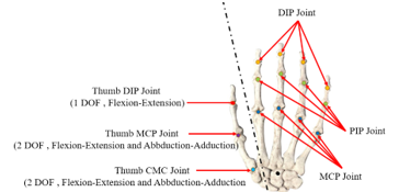
Figure 7: The Anatomy of Human Hand

Figure 8: The Wrist Movement
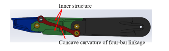
Figure 9: The Curvature of Four-bar Linkage
Many robotic hands have various thumb designs to accommodate the suitability of the hand, such as the number of DOFs, actuators, power transmission, and functionalities; thus, the design of the thumb is rarely defined. The main contribution for this paper is separated into 2 sections: the joint design, and the structure design. The joint design of the thumb is the same design as the controllable joint of four fingers which has a constant both distance and degree for pulling as shown in Figure 10. Normally, the thumb grasps an object by using both abduction-adduction movement and flexion-extension movement. The flexion-extension movement of thumb is used to press objects towards the palm of the hand while the abduction-adduction movement of thumb is used to grasp the various objects. Even though the abduction- adduction motion is very important for grasp [8], this robot hand challenges to design by using only flexion-extension movement to achieve the purpose of this hand in order to reduce the number of motors to be installed on forearm. From the reduction to 1 DOF per joint of the thumb, the importance of thumb angles must be emphasized, which affects the grasping performance of the hand. The motion analysis in SolidWorks program is required to test basic gestures and basic grasps such as handfuls, index-thumb, middle-thumb, cylindrical grasp, and spherical grasp before forming. From the analysis, the best angle for structure design of the thumb is 58.5 degrees in the top view and 28.5 degrees in the front view (Figure 11) to perform as many different gestures and basic grasps as possible in motion analysis of the SolidWorks program.
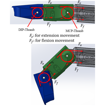
Figure 10: The Joint Design of the Thumb
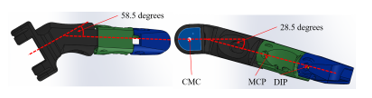
Figure 11: The Attachment Angle of the Thumb
2.2. Palm and Wrist Design
Generally, human hands can grasp objects by using the palm, all fingers, wrist, and skin. The palm is the part that connects the four fingers, thumb, and wrist that is coated by human skin. In the robotic field, the robot finger with no adduction-abduction movement was fixed angle between neighbor MCP joint of each finger at about 12 degrees [9]. The angle of neighbor MCP joint allows the hand to tightly grasp objects, increasing the area of routing tendons inside the hand, and decreasing the bending of PTFE tube around the MCP joint of the index finger in the palm. Each robotic hand has a different angle between neighbor MCP joint depending on the hand. From the analysis, it was found that 10 degrees is most suitable for this hand to gesture and grasp. The palm is designed by defining the middle finger as the reference point with 10 degrees of angle between neighbor MCP joints as shown in Figure 12.
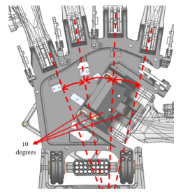
Figure 12: The Palm
In the palm, there is an apparatus that is used to arrange the PTFE tube and tendons from the wrist to each finger as shown in Figure 13. The CMC joint of the thumb was designed to angle the middle finger about 30 degrees (Figure 13) so that PTFE tubes inside the palm are easy to assemble and do not bend too much. The OK pose and check gesture can be performed by using this design. The OK posture is the index finger and thumb converge while the others are fully spread as Figure 14. The check posture is the index finger and thumb are fully spread while the others are fully bent same as the check symbol as shown in Figure 15. These 2 poses are the basic postures to hold objects and make various gestures of the hands. Since the direction of rotation of the CMC joint of the thumb is in a different direction of the tendon movement to other fingers, The bearing must be provided for changing the direction of pulling the tendons of the thumb as shown in Figure 16.
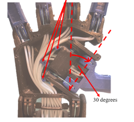
Figure 13: The Re-arranging of the PTFE Tube in the Palm
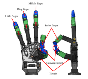
Figure 14: The Robotic Hand Performs OK Gesture
Figure 15: The Robotic Hand Performs Check Gesture
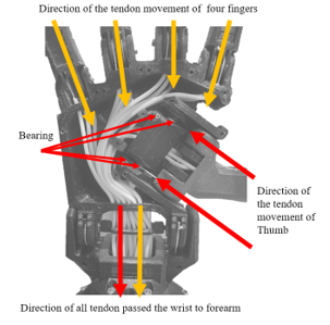
Figure 16: Direction of Tendon Movement in the Palm
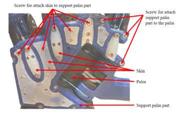
Figure 17: The Support Palm Part
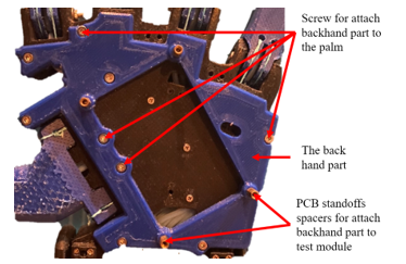
Figure 18: The Back Hand
The support palm part is the connector between palm and skin by using the screw (Figure 17). The backhand part attached behind the palm is used to install the test module (PCB for the connection wire of the encoder, multiplexer, and Arduino Uno board) by using PCB standoffs spacers and screw (Figure 18). The palm is assembled with an extension palm part on the wrist area to increase radius for pulling the tendon (Figure 19).
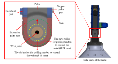
Figure 19: The Extension Palm Part
The wrist area has 3 components which are the main wrist, extension palm, and a support PTFE tube kit as shown in Figure 20. The main wrist is designed by integrating with PTFE tube to decrease friction force for pulling the tendon of wrist joint. In the middle of wrist joint is a support PTFE tube kit for re-arranging and supporting the PTFE tubes with tendons when the tendon is pulled by the motor. This support PTFE tube kit will keep the PTFE tube in place no matter how many degrees the wrist is tilted. The motor that controls the wrist joint will reduce the load caused by the tendon movement of all fingers. Main wrist is a connector between the hand and forearm that is used to re-arranging the PTFE tube same as a support PTFE tube kit and guides the tendon to attach the wrist joint. The range of motion of the wrist joint is from 0 to 180 degrees, the same as the wrist joint of human hand as shown in Figure 21.
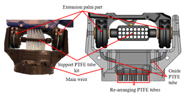
Figure 20: The Wrist
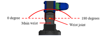
Figure 21: The Range of Motion of Wrist Joint
2.3. Skin of Fingertips and Palm
The entire skin is made of silicone (RA-22AB, RUNGART, Thailand) [10] forming with the use of PLA moles (3D printing). The skin of the palm consists of flat palm skin and half-ellipse palm skin (Figure 22). The thickness of flat palm skins and half-ellipse palm skins are about 1.5 mm and 4 mm respectively as shown in Figure 23. The skin of fingertips is the one of the main parts for grasping an object. Skin tips are used to increase friction force for tightening grip. These skin tips are wearable skin that has the same shape as fingertips with a thickness from the outside of the fingertips of about 2.5 mm as shown in Figure 24.
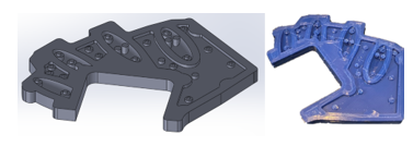
Figure 22: The Mold Skin of Palm
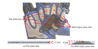
Figure 23: The Thickness of Palm Skin
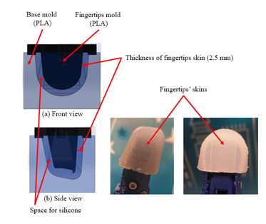
Figure 24: The Mold Skin of Fingertips
2.4. Forearm Design
The forearm contains the main forearm, connecting motor part, PTFE tube guide part, and cover. All servo motors, Arduino Uno board with Dynamixel shield, 12V fan, and PCB boards are installed in the forearm as shown in Figure 25. This Dynamixel servo motor (XL430 W250-t) has engineering plastic gear with an operating temperature from -5 to +72 °C. Long periods of heavy work of the motor will cause the accumulation of high temperature inside the forearm, so the design of the robot forearm must focus on temperature reduction to extend the motor life. The structure of the forearm must be a ventilated structure with a 12V vent exhaust fan to stabilize the operating temperature of the robotic hand. All PTFE tubes with tendons are routed following the PTFE guide from the motor in the forearm to each joint of the finger and wrist.
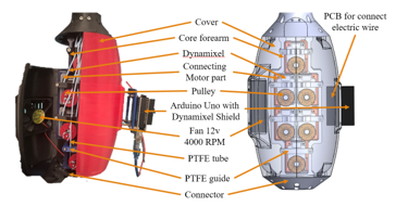
Figure 25: The Forearm
2.5. Actuation, Power Transmission and PLA Material
This hand uses 12 servo motors to control each actuated joint while underactuated joints (DIP joint of four fingers) move to follow the actuated joints (PIP joint of four fingers) by using a four-bar linkage mechanism. The actuators can transmit the power to control each joint by using a tendon with the PTFE tube. The PTFE tube [11] is used to protect the tendon and reduce the friction force between the tendon and the body part (PLA). The actuators of this robotic hand are XL430 W250-T from Dynamixel (TTL connection) because it has a suitable price with high torque and small size (Table 5). In addition, this actuator has precision to control with feedback sensors: position, current load, current temperature, etc. The tendon that is used to transmit the power from the actuators is a fishing tendon from Proberos. This tendon is made from 4 braids of Polyethylene (PE) with high max tension (36.2 Kg) and a small diameter (0.5 mm) costing about $1.5 per 100m as shown in Table 6. Because PLA filament has Young’s modulus of about 3.04 GPa but ABS material has Young’s modulus of about 1.97 GPa [12]. Therefore, the material for 3D printing parts uses PLA (Polylactic acid) filament with a cost (of $17.99 per Kg.) [13-14].
Table 5: Specification of Servo Motor [15]
| Name | Dynamixel (XL430 W250-T) |
| Stall Torque | 1.5 N.m |
| Stall Current | 1.4 A |
| Weight | 57 grams |
| Dimension | 28.5 x 46.5 x 34 mm. |
| No Load Speed (at 12V) | 61 rev/min |
| Resolution | 4096 pulse/rev, 360 degree |
| Gear Ratio | 258.5 : 1 |
| Operating Temperature | -5 to +72 °C |
| Connection | TTL |
| Feedback | Position, Load, Temperature, etc. |
| Material | Engineering Plastic |
| Price | $49.90 |
Table 6: Specification of Tendon [16]
| Name | Tendon |
| Brand | Proberos |
| Material | Polyethylene (PE) |
| Number of tendons | 4 braids |
| Outer Diameter | 0.5 mm |
| Max Tension | 36.2 Kg. |
| Price (100 m.) | $1.5 |
2.6. Cost Analysis
Generally, the range cost of a robotic hand is between $1,500 and $150,000. However, this robotic hand costs about $750 (as shown in Table 7) with 12 servo motors (Dynamixel) that can grasp objects and gestures similar to robotic hands that cost $1500 as proof in the results and experiment section. All parts of this robot hand are made from 3d print, designed for standard components that can be easily purchased locally and replaced. Moreover, robotic hands are designed to use as few motors as possible while keeping the ability to grasp various objects and gestures like other robotic hands as much as possible. The four-bar linkage mechanism is used to control the DIP joint related to the PIP joint in four fingers that can reduce one actuator per finger with the same number of movable joints as shown in the design section. Because all actuators are installed in the forearm, the low number of actuators in use saves costs and reduces the size and weight of the forearm. Thus, the price of this hand will be cheaper than the others.
Table 7: Price of Actuator and Material
| Name | Amount | Total Price ($) |
| Dynamixel XL430 W250-T | 12 | 598.80 |
| PLA (eSUN) 1 Kg. | 2 | 35.98 |
| Arduino Uno | 1 | 20 |
| Dynamixel shield | 1 | 19 |
| Fan 12V 4000 RPM | 1 | 1.5 |
| Power supply 12V 20A 240W | 1 | 9 |
| LCD meter and shunt (20A) | 1 | 9 |
| Electric wire AWG24 (30m.) | 2 | 5.50 |
| Tendon | 1 | 1.5 |
| Bolt and screw | – | 15 |
| Bearing, etc. | – | 35 |
| Total | 750.28 | |
3. Experiment and Results
All experiments are intended to prove the various performances of robotic hands compared to other expensive robotic hands such as grasping objects and gestures. The development of the anthropomorphic robotic hand in this paper has five experiments: grasping experiment, gesture experiment, motor temperature experiment, structure experiment, and repeatability experiment.
One of the performance experiments of the anthropomorphic robotic hand is the grasping experiment that uses various objects in daily life to test the grasping of the robot hand. The robotic hand grasp objects that are different in shape, weight, and size by using various grasping gestures as shown in the result of the grasping experiment.
The gesture experiment is the test of the robot hand to perform basic hand gestures and symbols that were chosen from daily hand posture. These two experiments were intended to test the ability to grip objects and perform gestures as designed.
The third experiment is the operating motor temperature test to determine whether the added structure and fan can reduce the temperature of the motor while operating. The motor temperature experiment uses Arduino Uno to read the current temperature from the feedback sensor of each motor.
The fourth experiment is the structure test of the degrees of dip and pip joints of the index finger, whether the DIP joint moves along with the PIP joint by using the four-bar linkage mechanism is similar to the equation used in the design.
The last experiment is the repeatability test of the robotic hand which shows how many errors each joint has. The structure experiment and repeatability experiment use magnetic encoders (AS5600) and an Arduino Uno board to read the current degree of each joint.
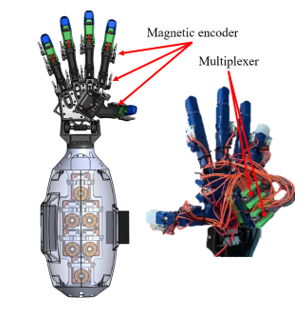
Figure 26: The Robotic Hand with Encoder Module
All experiments test only the joints of the fingers excluding the wrist. The controllable joints of this robot hand are 11 joints (3 joints for the thumb and 2 joints for each finger), therefore the maximum magnetic encoder used to read the angle of each joint is 11 positions. The Arduino Uno board connects to each magnetic encoder board by using I2C communication. All encoders cannot connect to the Arduino Uno board directly because each encoder has the same address (0x36). The I2C multiplexer (TCA9548A) is required to expand the I2C bus port and control multiple I2C devices with the same I2C address. One multiplexer can connect to 8 devices, so 2 multiplexers are enough. The address of the multiplexer can select a value from 0x70 to 0x77 by adjusting the values of the A0, A1, and A2 pins. The robot hand with an encoder module for the test is shown in Figure 26.
The average error values of the structure experiment and repeatability experiment are calculated from the following equation.
Table 8: The Meaning of Variable
| Variable | Meaning |
| Position value from encoder ( ) | |
| Target position value | |
| Total of test |
3.1. Result of Grasping Experiment
Generally, there are two kinds of grasping objects: power grasp and precision grasp. The precision grasp (tripod, two fingers, disk, and tip pinch) uses only fingertips with skin to hold small lightweight objects, while the power grasp (spherical, cylindrical, lateral pinch, lumbrical, large diameter, and platform) uses every part of the hand (fingertips, phalanx, palm, and skin) to grasp huge heavyweight objects. This experiment is the gripping test of the robot hand with power grasp and precision grasp by using ten grasping gestures: spherical (1.01-1.02), tripod (2.01-2.04), two fingers (3.01-3.02), cylindrical (4.01-4.05), lateral pinch (5.01-5.11), lumbrical (6.01), disk (7.01), large diameter (8.01-8.04), tip pinch (9.01), and platform (10.01) as shown in Tables 9 and Figure 27 respectively.
Because this robotic hand is controlled by humans to be used for handling various objects in daily life, The items used in the test must be found in daily life (differ in shape, weight, and size). There are 32 different objects that are used to test such as baseball, glue, pen, table tennis, bottle 600 ml, screwdriver, power bank, key, lighter, book, disk, and plaster. This test only focuses on that each item can be held in that posture without getting out of hand. The robot hand successfully grasped selected 32 different objects with 10 basic postures and can grasp objects up to 450 grams (bottle 600 ml) in cylindrical gripping gesture. The bottle made from plastic (PE) with a slippery skin and large diameter is grasped by cylindrical gesture (power grasp) to test the maximum weight that this hand can hold and to test whether robotic hands can handle things (not structural polishing). Holding a slippery object in this pose is a real gripping efficiency test of the robotic hand because the object may slip out of hand if the grasp is not tight enough. The proposed anthropomorphic design allows our robotic hand to grasp objects in a suitable gripping posture.
Table 9: Grasping Poses and Objects (a)
| Grasping Pose | Objects | ||
| Name | Dimension(mm) | Weight(g) | |
| Spherical (1) | Baseball (1.01) | 150 | |
| Tennis ball (1.02) | 65 | 55 | |
| Tripod (2) | Glue (2.01) | 20 | 11 |
| Pencil (2.02) | 7.8 | 4 | |
| Pen (2.03) | 9.8 | 6 | |
| Marker (2.04) | 10 | 7 | |
Table 9: Grasping Poses and Objects (b)
| Grasping Pose | Objects | ||
| Name | Dimension(mm) | Weight(g) | |
| Two Fingers (3) | Table tennis ball (3.01) | 39.5 | 2 |
| Golf ball (3.02) | 42.5 | 45 | |
| Cylindrical (4) | Bottle 600 ml (4.01) | 60 | 450 |
| Bottle skin care (4.02) | 50 | 72 | |
| Huge screwdriver (4.03) | 33.5 | 96 | |
| Trowel (4.04) | 32 | 27 | |
| Power bank (4.05) | 41.5 | 133 | |
| Lateral Pinch (5) | Key (5.01) | Thick 4.9 | 6 |
| Smart key (5.02) | Thick 0.8 | 4 | |
| Metal key (5.03) | Thick 2.2 | 39 | |
| Card reader (5.04) | Thick 8.5 | 3 | |
| Tweezers (5.05) | Thick 10 | 15 | |
| Small screwdriver (5.06) | 7.1 | 14 | |
| Pen (5.07) | 9.8 | 27 | |
| Hand drill (5.08) | 8.15 | 41 | |
| Lighter (5.09) | Thick 11 | 13 | |
| Tape (5.10) | Thick 18.5 | 22 | |
| Utility knife (5.11) | 9 | 15 | |
| Lumbrical (6) | Book (6.01) | 148.5 210 Thick 12 | 110 |
| Disk (7) | Disk (7.01) | 19 Thick 1.25 | 17 |
| Large Diameter (8) | Wire strippers (8.01) | 104 15 | 174 |
| Combination pliers (8.02) | 90 16.5 | 200 | |
| Diagonal cutter (8.03) | 93 11.5 | 25 | |
| Screwdriver box (8.04) | 67.5 17.25 | 263 | |
| Tip Pinch (9) | Wound closure plaster (9.01) | Thick 1 | 1 |
| Platform (10) | Document pouch (10.01) | 297 210 Thick 8 | 250 |
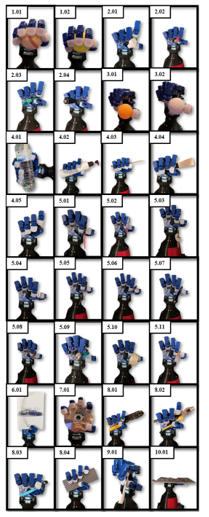
Figure 27: Robotic Hand Grasping Various Objects
3.2. Result of Gesture Experiment
This experiment is a test of the basic hand gestures and symbols that are chosen from frequently used in daily life. The robotic hand successfully posed 9 common gestures including high-five (1), peace (2), ok (3), index pointing (4), grasp (5), promise (6), love (7), check (8), and good job (9) as shown in Figure 28. The purpose of this robotic hand design does not focus on the adduction-abduction movement but to reduce the number of motors. Consequently, this hand cannot perform gestures that use the abduction-adduction movement such as fingers crossed, fig sign, and Vulcan salute.
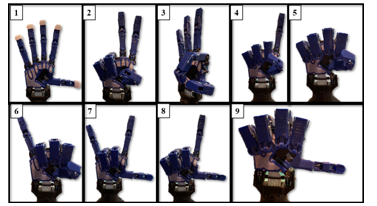
Figure 28: Gesture of Robot Hand
3.3. Operating Temperature of Motor Experiment
This experiment was to prove that an extra fan can reduce the temperature of the motor while operating by monitoring the motor temperature directly from the motor feedback sensor. The fan is installed to the cover of the forearm as shown in Figure 25. This is the performance experiment of a designed ventilated structure with a fan (12V 4000RPM). Usually, the motor can operate in the temperature range between -5 to +72 °C, but the operating motor temperature at 30 percent torque (enough for grasping objects) is between 55.0 °C to 68.0 °C (Figure 29) that close to the maximum temperature of the motor. This experiment uses Arduino Uno to control 12 motors and get feedback (Temperature) from motors in real-time (20 times). After installation and test, the range temperature of the operating motor is between 46.0 °C to 56.0 °C as shown in Figure 30. From the above, this experiment can prove that the fan can reduce the average temperature of the operating motor from 61.5 °C to 51.0 °C.

Figure 29: The Temperature of Each Operating Motor in Solid Structure
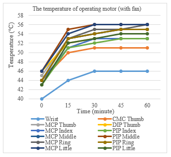
Figure 30: The Temperature of Each Operating Motor in Ventilated Structure
3.4. Structural of Four Common Fingers Experiment
The kinematic equation is used to design a four-bar linkage mechanism to move dip joints related to pip joints by using 1 actuator to control. This experiment is a structural experiment that tests the movement of dip joints related to pip joints (index finger) compared with the equation used in the design. This test uses magnetic encoder and Arduino Uno to check the degrees of each joint and control servo motors. The test will control the PIP joint and observe DIP joint of four common fingers around 100 times per position and compare with the kinematic equations from [1]. While the PIP joint is controlled by servo motor which moves from 0.0 degree to 78.0 degrees and back to 0.0 degree (100 times), the DIP joint moves from 0.0 degree to 68.1 degrees following the PIP joint by using a four-bar linkage mechanism. When the PIP joint moves from 0.0 degree to 78.0 degrees, the DIP joint will move from 0 to 69.3 degrees by calculating from the equation. After testing, the structure can move according to the equation with an error of fewer than 1.6 degrees and the PIP joint of index finger has an error of about 0.1 degrees as shown in Tables 10 and 11.
Table 10: Structural Test (Degree)
| No | Encoder (statistic method) | Equation | Avg. Error (DIP) | |||
| PIP Joint (Deg) | DIP Joint (Deg) | DIP Joint (Deg) | ||||
| Average | SD | Average | SD | |||
| 1 | 78.1 | 0.2 | 68.1 | 0.2 | 69.3 | 1.2 |
| 2 | 31.1 | 0.2 | 29.1 | 0.1 | 27.5 | 1.6 |
Table 11: The Average Error of PIP Joint (Degree)
| No | Encoder (statistic method) | Target | Avg Error (PIP) | |
| PIP Joint (Deg) | PIP Joint (Deg) | |||
| Average | SD | |||
| 1 | 78.1 | 0.2 | 78.0 | 0.1 |
| 2 | 31.1 | 0.2 | 31.0 | 0.1 |
3.5. Repeatability Experiment
The repeatability test of robotic hands using Arduino Uno boards to control 2 positions of the motor and read the position of each joint from magnetic encoder modules (12-bit resolution or about 0.08° per count). The Arduino Uno board can read the degree of each joint in real-time via a magnetic encoder. This board control motor moves forward and backward to the same position around 200 times per cycle. To conclude the data in the table, all information is expressed as the statistical method (max, min, standard deviation, average). This test is divided into two experiments which are the repeatability test of the index finger, and the repeatability test of the robot hand. From all of the experiments, this robot hand has a maximum error of repeatability of about 1.2 degrees.
First, the repeatability test of the index finger uses 3 magnetic encoders with Arduino Uno to measure the degree of MCP, PIP, and DIP joint of the index finger. This test has three sets of moving positions and each set has two positions that are selected from the range of motion of each joint. From the result, we found that the maximum error of the repeatability test of the index finger is 0.2 degrees as shown in Table 12.
Table 12: Repeatability Test of Index Finger (Degree)
| Number of Sets | Statistical Method | Target | Avg Error | ||||
| Min | Max | Avg | SD | ||||
| MCP (1) | Pos 1 | 0.0 | 0.6 | 0.1 | 0.1 | 0.0 | 0.1 |
| Pos 2 | 84.0 | 85.1 | 84.1 | 0.2 | 84.0 | 0.1 | |
| PIP (1) | Pos 1 | 0.0 | 2.0 | 0.1 | 0.2 | 0.0 | 0.1 |
| Pos 2 | 78.0 | 79.8 | 78.2 | 0.4 | 78.0 | 0.2 | |
| MCP (2) | Pos 1 | 0.0 | 0.5 | 0.1 | 0.1 | 0.0 | 0.1 |
| Pos 2 | 55.0 | 56.1 | 55.1 | 0.2 | 55.0 | 0.1 | |
| PIP (2) | Pos 1 | 0.0 | 0.5 | 0.1 | 0.1 | 0.0 | 0.1 |
| Pos 2 | 67.0 | 69.0 | 68.2 | 0.3 | 68.0 | 0.2 | |
| MCP (3) | Pos 1 | 0.0 | 0.5 | 0.1 | 0.1 | 0.0 | 0.1 |
| Pos 2 | 70.0 | 72.0 | 70.2 | 0.4 | 70.0 | 0.2 | |
| PIP (3) | Pos 1 | 0.0 | 0.5 | 0.1 | 0.1 | 0.0 | 0.1 |
| Pos 2 | 34.8 | 36.2 | 35.1 | 0.2 | 35.0 | 0.1 | |
Second, the repeatability experiment of the robot hand is testing the error of all controllable joints to find the maximum error of the repeatability test of the robot hand by using 11 magnetic encoders and Arduino Uno. This test has settings and methods the same as the repeatability test of the index finger. The maximum error of this test is 1.2 degrees at CMC joint of thumb as shown in Tables 13 and 14. The PTFE tubes with tendons are routed through the CMC joint to control the MCP and DIP joints of the thumb while the other joints have only tendons that route through. The maximum error of the repeatability test is on the CMC joint.
Table 13: Repeatability Test of Robot Hand (Degree)
| Finger Names | Name of Joint | Statistical Method (Deg) | ||||
| Min | Max | Avg. | SD | |||
| Thumb | CMC | Pos 1 | 0.0 | 2.0 | 0.1 | 0.2 |
| Pos 2 | 98.0 | 100.0 | 99.2 | 0.3 | ||
| MCP | Pos 1 | 0.0 | 0.5 | 0.1 | 0.1 | |
| Pos 2 | 76.0 | 77.0 | 76.1 | 0.1 | ||
| DIP | Pos 1 | 0.0 | 2.0 | 0.1 | 0.2 | |
| Pos 2 | 39.0 | 40.0 | 39.1 | 0.2 | ||
| Index | MCP | Pos 1 | 0.0 | 0.5 | 0.1 | 0.1 |
| Pos 2 | 70.0 | 71.3 | 70.3 | 0.5 | ||
| PIP | Pos 1 | 0.0 | 0.6 | 0.1 | 0.1 | |
| Pos 2 | 78.0 | 79.5 | 78.5 | 0.4 | ||
| Middle | MCP | Pos 1 | 0.0 | 0.5 | 0.1 | 0.1 |
| Pos 2 | 98.0 | 99.2 | 98.4 | 0.2 | ||
| PIP | Pos 1 | 0.0 | 0.5 | 0.1 | 0.1 | |
| Pos 2 | 89.0 | 90.0 | 89.4 | 0.2 | ||
| Ring | MCP | Pos 1 | 0.0 | 1.2 | 0.1 | 0.2 |
| Pos 2 | 98.0 | 98.5 | 98.2 | 0.1 | ||
| PIP | Pos 1 | 0.0 | 0.5 | 0.1 | 0.1 | |
| Pos 2 | 89.0 | 90.6 | 89.2 | 0.3 | ||
| Little | MCP | Pos 1 | 0.0 | 0.5 | 0.1 | 0.1 |
| Pos 2 | 80.0 | 81.9 | 80.4 | 0.6 | ||
| PIP | Pos 1 | 0.0 | 0.5 | 0.1 | 0.1 | |
| Pos 2 | 86.0 | 87.2 | 86.2 | 0.3 | ||
Table 14: Target and Average Error of the Repeatability Test of Robot Hand (Degree)
| Finger Names | Name of Joint | Target (Deg) |
Avg (Deg) |
Avg Error (Deg) |
|
| Thumb | CMC | Pos 1 | 0.0 | 0.1 | 0.1 |
| Pos 2 | 98.0 | 99.2 | 1.2 | ||
| MCP | Pos 1 | 0.0 | 0.1 | 0.1 | |
| Pos 2 | 76.0 | 76.1 | 0.1 | ||
| DIP | Pos 1 | 0.0 | 0.1 | 0.1 | |
| Pos 2 | 39.0 | 39.1 | 0.1 | ||
| Index | MCP | Pos 1 | 0.0 | 0.1 | 0.1 |
| Pos 2 | 70.0 | 70.3 | 0.3 | ||
| PIP | Pos 1 | 0.0 | 0.1 | 0.1 | |
| Pos 2 | 78.0 | 78.5 | 0.5 | ||
| Middle | MCP | Pos 1 | 0.0 | 0.1 | 0.1 |
| Pos 2 | 98.0 | 98.4 | 0.4 | ||
| PIP | Pos 1 | 0.0 | 0.1 | 0.1 | |
| Pos 2 | 89.0 | 89.4 | 0.4 | ||
| Ring | MCP | Pos 1 | 0.0 | 0.1 | 0.1 |
| Pos 2 | 98.0 | 98.2 | 0.2 | ||
| PIP | Pos 1 | 0.0 | 0.1 | 0.1 | |
| Pos 2 | 89.0 | 89.2 | 0.2 | ||
| Little | MCP | Pos 1 | 0.0 | 0.1 | 0.1 |
| Pos 2 | 80.0 | 80.4 | 0.4 | ||
| PIP | Pos 1 | 0.0 | 0.1 | 0.1 | |
| Pos 2 | 86.0 | 86.2 | 0.2 | ||
4. Conclusions
From the experiment, this anthropomorphic robot hand can grasp selected 32 different objects commonly found in daily life with 10 basic gripping postures and can perform 9 basic gestures. The other gestures that this hand cannot perform use the abduction-adduction movement such as fingers crossed, fig sign, and Vulcan salute. This robot hand can increase grasping posture and hand gesture by adding the abduction-adduction motion with the smallest actuators into the MCP joint of each finger. In addition, the robot hand can grasp an object up to 450 grams. When grasping huge objects, we usually use the cylindrical grasp (power grasp posture) as in the grasping experiment section. From the above results, it can be found that the motor can sufficiently transmit force and torque to the fingers and fingertips in order to grasp the 450 grams object. By using a Lateral grasp, the anthropomorphic hand can pick up small objects such as keys and utility knives with fingertips. In addition, the proposed robot hand has sufficient force and rigidity to grasp various objects while the cost is lower than other designs. The equations used in the design proven that the structure can move according to the equation with an error value of about 1.6 degrees. In the repeatability experiment, this robot’s hand has a maximum error of repeatability of about 1.2 degrees.
We have designed and prototyped an open-source anthropomorphic robotic hand for teleoperated robots with a detailed design process for further developers. We use 3D printing and common components for assembling. The four-bar linkage mechanism is used to mimic the relative motion between DIP and PIP joints same as the human finger, while also reducing the number of motors. We experimentally that our proposed robotic hand design has good repeatability in finger motions and grasping daily objects. This paper explains how to design a robot hand, it can be adjusted to any desired size by using the equation given above.
Design of an Open-Source Anthropomorphic Robotic Hand for Telepresence Robot is available for study and development, which can be found at the following site. https://github.com/Jittaboon-tri/Anthropomorphic-Robotic-Hand
Conflict of Interest
The authors declare no conflict of interest.
Acknowledgment
We want to give acknowledgements to AI for all projects for the financial support in our research, Institute of Field Robotics (FIBO), and King Mongkut’s University of Technology Thonburi (KMUTT) and Fundamental Fund (Basic Research Fund) for supporting fund.
- J. Trichada, T. Wimonrut, N. Tirasuntarakul, T. Choopojcharoen, B. Sakulkueakulsuk, “Design of an open source anthropomorphic robotic finger for telepresence robot,” ACM International Conference Proceeding Series, 62–66, 2021, doi:10.1145/3467691.3467704.
- S.C. Jee, M.H. Yun, “An anthropometric survey of korean hand and hand shape types,” International Journal of Industrial Ergonomics, 53, 10–18, 2016, doi:10.1016/j.ergon.2015.10.004.
- V. Doroshenko, O. Mul, O. Kravchenko, “Mathematical relations for harmonization with technical and decorative casting nature,” Boundary Field Problems and Computer Simulation, 55(December), 44–49, 2016, doi:10.7250/bfpcs.2016.007.
- P.G. Narasimha-shenoi, Golden ratio in human anatomy, Thesis, Government College Chittur, 2014, doi:10.13140/2.1.2265.9526.
- D. Persaud, J.P. O, “Fibonacci series, golden proportions, and the human biology,” Austin Journal of Surgery, 2(5), 1–6, 2015, ISSN : 2381-9030.
- S.A. Powell, A review of anthropomorphic robotic hand technology and data glove based control, Masters Thesis, Virginia Polytechnic Institute and State University 2016.
- M. Controzzi, C. Cipriani, B. Jehenne, M. Donati, M.C. Carrozza, “Bio-inspired mechanical design of a tendon-driven dexterous prosthetic hand,” 2010 Annual International Conference of the IEEE Engineering in Medicine and Biology Society, EMBC’10, (i), 499–502, 2010, doi:10.1109/IEMBS.2010.5627148.
- D. Choi, D.-W. Lee, W. Shon, H.-G. Lee, “Design of 5 D.O.F robot hand with an artificial skin for an android robot,” The Future of Humanoid Robots – Research and Applications, (January), 2012, doi:10.5772/26282.
- W.S. You, Y.H. Lee, H.S. Oh, G. Kang, H.R. Choi, “Design of a 3D-printable, robust anthropomorphic robot hand including intermetacarpal joints,” Intelligent Service Robotics, 12(1), 1–16, 2019, doi:10.1007/s11370-018-0267-8.
- Material property of RA-22AB, https://www.resinrungart.com/ra_22ab.html, Jan. 2022.
- The coefficient of the PTFE tube,https://www.fluorotherm.com/technical-information/ materials-overview/ptfe- properties/, Jan. 2022.
- Z. Su, K. Inaba, A. Karmakar, A. Das, “Characterization of mechanical property of pla-abs functionally graded material fabricated by fused deposition modeling,” Proceedings of ASME 2021 Gas Turbine India Conference, GTINDIA 2021, (December), 2021, doi:10.1115/GTINDIA2021-76025.
- Material price of polymaker, https://us.polymaker.com, Jan. 2022.
- Material price of eSUN, https://www.esun3d.com, Jan. 2022.
- Specification of Dynamixel servo motor,https://www.robotis.us/dynamixel-xl430-w250-t/, Jan. 2022.
- Speciafication of tendon,https://www.lazada.co.th/products/1-2-proberos-x4-100m-bluegreenyellowredgrey-pe-4-5-100-thailand-fishing-mall-fishing-line-i2161246830-s7196994582.html, Jan 2022.