Metamaterial-Inspired Compact Single and Multiband Filters

Adv. Sci. Technol. Eng. Syst. J. 7(4), 92–97 (2022);
 DOI: 10.25046/aj070412
In this paper, Compact bandpass filters have been designed. A single bandpass filter was designed using novel triple concentric complementary split-ring resonators placed along the microstrip line in the ground plane. Gaps and via were placed on the microstrip line to control electromagnetic characteristics, resulting in a single bandpass filter. In turn, spiral resonators were attached to the microstrip transmission line at the gaps in the transmission line to obtain a compact dual passband filter. Stepped impedance microstrip line and T-shaped stubs were attached to the microstrip line in between spiral resonators. The structure designed resulted in a Triple bandpass filter. A fractional bandwidth of 3% was achieved at the center frequency of 3GHz. The filter had a 1.5dB insertion loss which is the minimum value in the operating frequency band. The filter resonance frequency was 1.32 GHz and 2.47GHz which have a fractional bandwidth of 7.5% and 4.85% respectively and the corresponding insertion loss was 1.3dB and 1.8dB respectively. The triple bandpass filter had a fractional bandwidth of 1.16%, 11.4%, and 1.86%, centered at 1.29 GHz, 2.27 GHz, and 3.21GHz with 1.6dB, 1.3dB, and 1.8 dB insertion loss at the respective frequencies. The proposed bandpass filters are useful for GPS, WLAN, WiMAX, and radar applications.
1. Introduction
In modern wireless communication systems, there is an urgent need for compact filters with low insertion loss, and high selectivity to transmit a specific band of frequencies. Bandpass filters allow desired frequencies and reject unwanted frequencies. The basic requirement for wireless communications is portability. For wireless devices to be portable, internal components must be as compact as possible. Metamaterial provides the opportunity to exploit its unusual properties to control the electromagnetic characteristics of microwave devices such as filters, antennas, couplers, power dividers, etc., to design compact devices with better performance characteristics. The controlling of electromagnetic parameters is done by the attainment of negative permittivity and/or permeability over a certain range of frequencies by engineering materials such as altering their dimensions or creating gaps for better performance of microwave devices. In [1], backward wave propagation with split ring resonators which are loaded along the transmission line is demonstrated. In [2], a bandpass filter is designed using a high-temperature superconducting structure based on SRRs, but the filter was large. In [3] S-shaped complementary resonant structures were used to design a bandpass filter, but insertion loss was high in the passband. In [4], a complementary split-ring resonator (CSRR) based dual-mode patch bandpass filter is proposed, but the filter was large. In [5], a hybrid bandpass filter using substrate integrated waveguide and CSRR is proposed, but it had high insertion loss. In [6], a bandpass filter using multiple SRR and CSRRs was designed, but with large size. In [7], a microstrip bandpass filter for X band applications is presented. The filter is designed with SRRs but had high insertion loss with large size. In [8], a bandpass filter using an optimized coupling matrix synthesis method is designed, which was large. In [9], a bandpass filter based on half mode substrate integrated waveguide, periodic CSRRs, and defected ground structures is proposed, but is large. In [10], a low-profile metamaterial bandpass filter loaded with a four-turn complementary spiral resonator for wireless power transfer applications is designed. In [11], a full mode substrate integrated waveguide bandpass filter using CSRR is designed, that has high insertion loss.
Multiband filters are in demand to avoid the crowding of multiple devices for different applications. To accommodate multiple applications within a device and have better performance characteristics becomes challenging for the researchers. Numerous methods have been proposed. In [12], two dual bandpass filters one using CSRRs, complementary spiral resonators (CSR), and tapered substrate integrated waveguide; another one with CSRRs, CSR, and substrate integrated waveguide are designed. In [13], a filter with dual passbands using tapered SRRs which consist of asymmetric shape square rings with interlinking is developed. In [14], a bandpass filter with CSRR and defected ground structures using substrate-integrated waveguide technology is proposed. In [15], a dual bandpass filter based on coupling between two identical SRRs and a CSRR is presented. In [16], varactor diodes were loaded on split ring slots to achieve a unit cell for frequency tunability is designed. In [17], a bandpass filter was designed for three bands using stub loading on resonators. The resonators were further coupled with internal resistors for dual mode operation. In [18], a compact three stubs loaded open-loop resonator-based triple bandpass filter is presented. In [19], resonators with open loops for filters with three pass bands are designed. In [20], a bandpass filter for triple bands using metamaterials is proposed. Rectangular stubs with a meander line were used in the design. The filters mentioned are large [12-20].
In this paper, metamaterial-inspired LC resonant structures were implemented to design a single bandpass filter. Firstly, gaps were formed along the microstrip transmission line. Via filled with copper was introduced along the microstrip transmission line. Triple CSSRs were etched in the ground plane just beneath the microstrip transmission line. Bandpass response with better sensitivity and insertion loss was achieved using the above configuration. The dual bandpass filter was designed by adding spiral resonators connected to the gaps introduced in the microstrip line to the proposed single bandpass filter. Stepped impedance resonant microstrip line and T-shaped stubs were added between spiral resonators attached to the microstrip line to the proposed dual bandpass filter to design a triple bandpass filter that helps in improving return loss.
2. Design Methodology
The microstrip transmission line allows all frequencies to pass through it. An electric field was induced from the microstrip line to a ground plane and a magnetic field around the microstrip transmission line. A bandpass filter was designed in this paper first by stopping all frequencies using gaps along the microstrip transmission line. By introducing a via filled with copper along the microstrip transmission line between the microstrip line and ground plane through the substrate, a passband was observed with high insertion loss and low return loss. Triple complementary concentric split-ring resonators were etched in the ground plane along the microstrip transmission line to act as LC resonant structure was excited by a time-varying electric field parallel to its axis and provided a single negative permittivity medium which introduced a passband over a certain range of frequencies but with low return loss in the passband and better insertion loss; sensitivity from passband to stopband transition and vice versa was also observed. This combination of gaps, vias, and complementary structures was introduced along with the transmission line resulting in passband response with better insertion loss and sensitivity by choosing appropriate dimensions for concentric rings, microstrip lines, vias, and gaps. Spiral resonators with optimum dimensions were connected to the gaps of the microstrip transmission lines which are coupled electrically to the triple concentric split ring resonators introducing one more passband, which helps in reducing insertion loss. Thus, a compact dual bandpass filter is designed with better insertion loss and high selectivity in the first band, and better insertion loss and selectivity in the second band. The stepped impedance resonant microstrip line for the proposed dual bandpass filter generated one more passband and the T-shaped stubs attached to the microstrip line in between spiral resonators helped to improve return loss. Thus, a compact triple bandpass filter was designed.
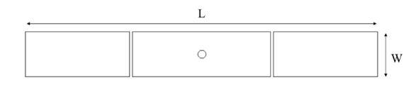
Figure 1: Top view of the single bandpass filter
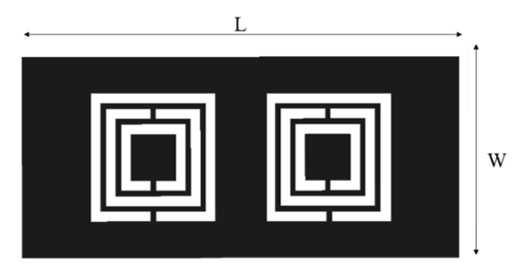
Figure 2: Bottom view of the single bandpass filter
The proposed filters were realized on RT Duroid 3010 substrate that has a height of 0.13 mm, and a dielectric constant of 10.2. Microstrip line made with 35 µm thickness copper material had a width of 2.25 mm for better impedance matching with 50Ω transmission line. Gaps along the microstrip line were 0.15 mm while via filled with copper had a diameter of 0.4 mm, and placed through the substrate from the microstrip line to the ground plane. Complementary split rings had a width of 0.4 mm and gaps in them had a width of 0.2 mm with gaps between concentric rings 0.2 mm. The outer ring had a length and width of 5 mm on each side. The top and bottom views of the simulated single bandpass filter are shown in Figure.1 and 2 respectively. The dimensions of the proposed filter were 17.5 mm×7.81 mm which was approximated by the guided wavelength λg at the center frequency as 0.55 λg ×0.25 λg.
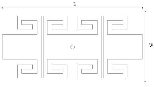
Figure 3: Top view of the dual bandpass filter.
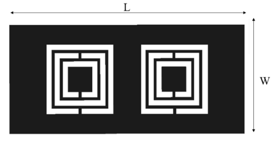
Figure 4: Bottom view of a dual bandpass filter
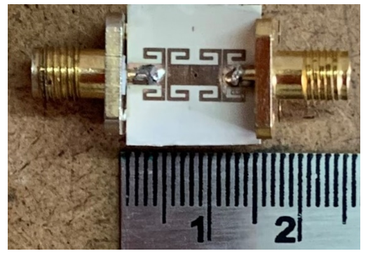
Figure 5: Fabricated top view of a dual bandpass filter
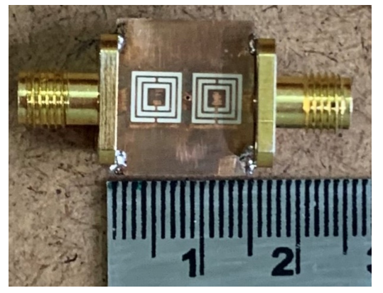
Figure 6: Fabricated bottom view of the dual bandpass filter
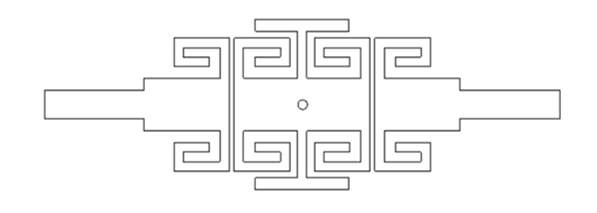
Figure 7: Top view of the triple bandpass filter
The dimensions of the filter were 14 mm × 15.81mm which is approximately 0.19 λg × 0.21 λg, where λg is the guided wavelength at the lower resonant frequency. The top and bottom views of the simulated dual bandpass filter are shown in Figures.3 and 4 while that of fabricated prototypes are shown in Figures.5 and 6, respectively.
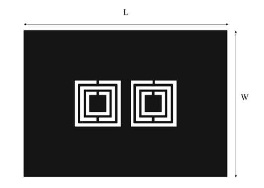
Figure 8: Bottom view of the triple bandpass filter
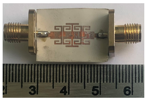
Figure 9: Fabricated top view of Triple bandpass filter
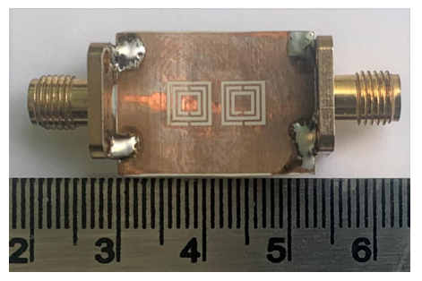
Figure 10: Fabricated bottom view of Triple bandpass filter
The dimensions of the designed filter were 22mm × 15.81mm which can also be represented as 0.3 λg × 0.2 λg, where the guided wavelength (λg) is calculated at the lowest resonant frequency. The structure of the triple bandpass filter is shown in Figures 7 and 8, while that of the fabricated filters is shown in Figures 9 and 10.
3. Results and Discussion
The proposed bandpass filters were designed and simulated with the help of the Ansys HFSS simulator using the finite element method (FEM). Ansys HFSS is three-dimensional electromagnetic simulation software. This software is used for designing and simulating high-frequency electronic products such as antennas, filters, etc., The most important component of FEM is mesh. Mesh can handle inaccuracies in the 3D model and produce reliable results consistently. The simulation results for the single bandpass filter are shown in Figure.11. The fractional bandwidth of the proposed filter is 3% at the 3GHz center frequency. The minimum insertion loss of the filter is 1.5 dB. The roll-off rate of the filter is 58.8 dB/GHz on the lower side and 67.8 dB/GHz on the upper side.
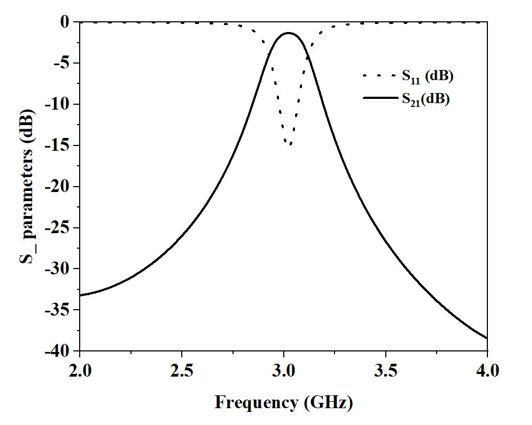
Figure 11: Simulation S-parameters of the single bandpass filter
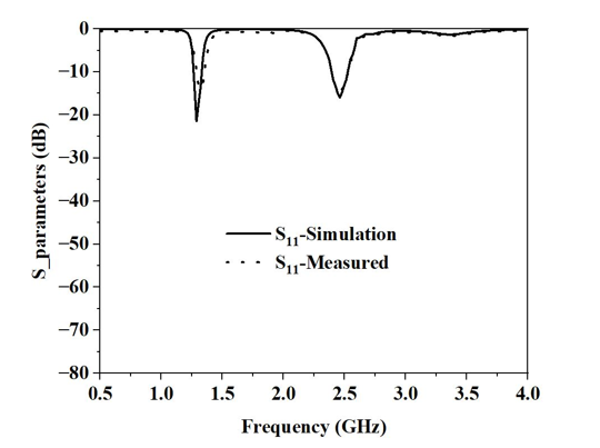
Figure 12: Simulation and measured return loss S11 of the dual bandpass filter
The performance of the proposed filters was validated by measuring S_parameters using vector network analyzer N5222A. The simulation and measured S11 and S21 results for the dual bandpass filter are shown in Figure.12 & Figure.13 respectively. The simulated dual bandpass filter has center frequencies at 1.3 GHz and 2.46 GHz. The fractional bandwidth was 8% for the first band, and 4.85% for the second band. The minimum insertion loss obtained was 1.15 dB and 1.7 dB for both bands respectively. The return loss was 21 dB for the first band and 17 dB for the second band. The measured dual bandpass filter had center frequencies at 1.32 GHz and 2.47 GHz. The fractional bandwidth of the proposed filter was 7.5% for the first band and 4.85% for the second band. The minimum insertion loss obtained was 1.3 dB for the first band and 1.8 dB for the second band. The return loss was 15 dB for the first band and 16 dB for the second band. The roll-off rate for the first band was 203 dB/GHz on the lower side, 64 dB/GHz on the upper side, for the second band 35 dB/GHz on the lower side, and 94.6 dB/GHz on the upper side. The electrical size of the dual bandpass filter is 0.039 λg2.
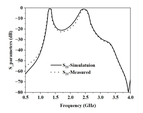
Figure 13: Simulation and measured insertion loss S21 of the dual bandpass filter
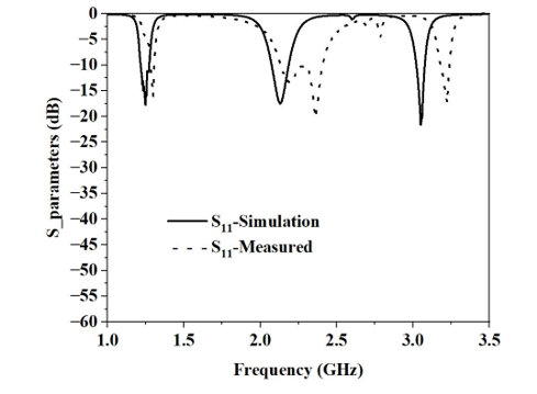
Figure 14: Simulation and measured return loss S11 of the triple bandpass filter.
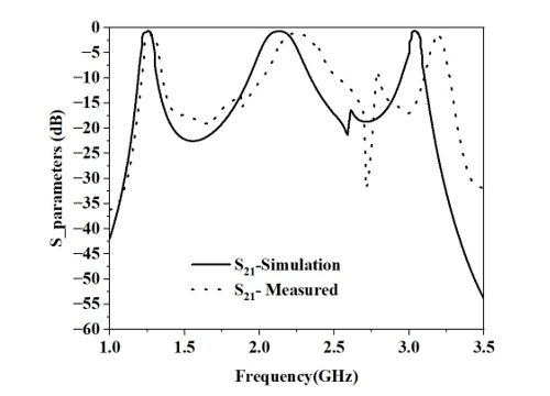
Figure 15: Simulation and measured insertion loss S21 of the triple bandpass filter.
The simulation results and those determined experimentally for S11 and S21 of the triple bandpass filter are shown in Figure.14 & Figure.15 respectively. The simulated triple bandpass filter has center frequencies at 1.27GHz, 2.2GHz, and 3GHz. The fractional bandwidth for the first band is 1%, for the second band is 6%, and for the third band is 1.8%. The minimum insertion loss obtained was 1.2 dB, 0.99 dB, and 1.5 dB respectively. The return loss was 18 dB,17 dB, 22 dB respectively. The measured triple bandpass filter had center frequencies at 1.29 GHz, 2.27 GHz, and 3.21 GHz. The fractional bandwidth was 1.16%, 11.4%, and 1.86% for all three bands respectively. The minimum insertion loss obtained was 1.6 dB, 1.3 dB, and 1.8 dB respectively in the passband. The return loss was 17 dB,13 dB,18 dB respectively. The roll-off rate for the first band was 262 dB/GHz on the lower side and 115 dB/GHz on the upper side, for the second band it was 56 dB/GHz on the lower side, 49 dB/GHz on the upper side, for the third band it was 47 dB/GHz on the lower side and 180 dB/GHz on the upper side. The electrical size of the triple bandpass filter is 0.06 λg2.
Table 1: Single bandpass filter comparison table
| References | Center frequency (GHz) | Fractional Bandwidth (%) | Insertion loss (dB) | Electrical size (λg2) |
| 4 | 3.41 | 3.5 | <1 | 0.38 |
| 5 | 10 | 12 | 1.59 | 0.39 |
| 6 | 9.1 | 3 | 0.04 | 0.58 |
| 7 | 9 | <1 | 2.24 | 0.92 |
| 8 | 2.4 | 12.5 | 0.7 | 0.39 |
| Single bandpass filter | 3
|
3 | 1.5 | 0.13 |
The measured dual bandpass filter operating at center frequencies of 1.32 GHz and 2.47 GHz with a fractional bandwidth of 7.5% and 4.85% respectively has a 0.039 λg2 size is compact and useful for GPS and WLAN applications. The measured triple bandpass filter operates at center frequencies of 1.29 GHz,2.27 GHz, and 3.21 GHz with a fractional bandwidth of 1.16%, 11.4%, and 1.86% has 0.06 λg2 is compact and useful for GPS, WLAN, WiMAX applications. The simulation and measurement results were in good agreement. The difference in measured results is due to dimensional tolerances during the etching of the copper material at the time of fabrication. The right shift in the measurement results may be due to a delta reduction in the dimensions of the design during fabrication.
From table.1., it is observed that the single bandpass filter is compact. From table 2, it is observed that the dual bandpass filter is compact. From table.3., it is observed that the triple bandpass filter is compact.
Table 2: Dual bandpass filter comparison table
| References | Center frequency (GHz) | Fractional bandwidth (%) | Insertion loss (dB) | Electrical size (λg2) | |
| 12 | Type 1 | 4.32,5.52 | 5.76,4.98 | 2.79,2.92 | 0.22 |
| Type 2 | 3.84,4.96 | 6.69,5.28 | 1.65,3.33 | 0.07 | |
| 13 | 8.89,11.04 | <1, <1 | 2.68,2.61 | 3.3 | |
| 14 | 5.57,7.84 | 6.8,4.1 | 1.8,2 | 0.22 | |
| 15 | 5.02,8.92 | <1, <1 | 6.22,5.23 | 0.17 | |
| Dual bandpass filter | 1.32, 2.47
|
7.5,4.85 | 1.3,1.8 | 0.039 | |
Table 3: Triple bandpass filter comparison table
| References | Center frequency (GHz) | Fractional bandwidth (%) | Insertion loss (dB) | Electrical size (λg2) |
| 16 | 8.63,9.86,11.62 | 2.4,3.3,2.5 | 0.8,1.4,1.7 | 0.97 |
| 17 | 1.575,2.4,3.45 | 10,5,11 | 0.7,1.14,0.3 | 0.54 |
| 18 | 1.93,3.6,4.89 | 19.2, 11.6,2.86 | – | 0.076 |
| 19 | 1.96,2.6,3.9 | 5,11,3 | 1.5,0.6,1.83 | 0.41 |
| 20 | 2.1,5.7,7.3 | 57.1,8.7,4.1 | 0.8,1.6,2.4 | 0.073 |
| Triple bandpass filter | 1.29,2.27,3.21 | 1.16,11.4,1.86 | 1.6,1.3,1.8 | 0.06 |
4. Conclusion
A compact single bandpass filter using novel Triple concentric complementary split-ring resonator structure, gaps, and via along the microstrip line was proposed. The proposed single bandpass filter is useful for s band radar applications. The proposed filter has better insertion loss and sensitivity with a compact size. By adding spiral resonators to the proposed single bandpass filter design configuration, the dual bandpass filter was designed, fabricated, and measured resulting in a compact size, better insertion loss, and sensitivity. The proposed dual bandpass filter is useful for GPS and WLAN applications. The compact triple bandpass filter was designed using a stepped impedance microstrip line and T-shaped stubs for the dual bandpass configuration. The Triple bandpass filter is useful for GPS, WLAN, and WiMAX applications.
- R. Marques, F. Martin, and M. Sorolla, “Metamaterials with Negative Parameters: Theory, Design, and Microwave Applications”. Hoboken, NJ: Wiley, 2008.
- Cheng Tan, Yu Wang, Zhong Ming Yan et.al., “Superconducting filter based on split ring resonator structures”, IEEE Transactions on Applied Superconductivity, 29(4), 1-4, 2019, doi:10.1109/TASC.2019.2891017.
- A. K. Horestani, M. D. Sindreu, J. Naqui et.al., “S-Shaped complementary split ring Resonators and their application to compact differential bandpass filters with common-mode suppression”, IEEE Microwave and Wireless Components Letters, 24,(3), 149-151, 2014, DOI: 10.1109/LMWC.2013.2291853.
- Y. Cheng, L. Zeng, W. Lu, “A compact CSRR- based dual-mode patch bandpass filter”, IEEE conference, November 2015, DOI: 10.1109/IMWS-AMP.2015.7325010.
- Y. Zheng, Y. Zhu, Yuandan “Compact hybrid bandpass filter using SIW and CSRRs with wide Stopband rejection”, IEEE conference, 2020, DOI: 10.1109/APMC47863.2020.9331361.
- S. Chandra “X-Band Metamaterial Bandpass Filter Design”, International Journal of Engineering Research & Technology (IJERT), 10 (5), 1004-1006, 2021, ISSN: 2278-0181.
- R. L. Defitri and A. Munir, “X-band microstrip narrowband BPF composed of the split ring resonator”, Progress in Electromagnetic Research Symposium (PIERS), 3468-3471, 2016, DOI: 10.1109/PIERS.2016.7735347.
- A. A. Ibrahim, M. A. Abdalla, A. B. Abdelrahman, “Wireless bandpass Filters build on metamaterials” Microwaves & RF.57(5), 1-7, 2018, ISSN: 07452993.
- B. Fellah, N. Cherif, M. Abri et.al., “CSRR-DGS bandpass filter based on half mode substrate integrated waveguide for X-Band applications”, Advanced Electromagnetics, 10(3), 39-42, 2021, doi:10.7716/aem. v10i3.1782.
- R. Keshavarz and N. Shariati, “Low profile metamaterial bandpass filter loaded with 4-Turn complementary spiral resonator for WPT applications”, IEEE conference, 50-53, 2020, ISBN: 9781728160443.
- S. Moitra, S. Nayak, R. Regar et.al., “Circular complementary split-ring resonators (CSRR) based SIW BPF”, Second International Conference on Advanced Computational and Communication Paradigms (ICACCP), 2, 1-5, 2019, ISBN: 9781538679890.
- H.Y. Gao, Z. X. Tang, X. Cao, et.al., “Compact dual-band SIW filter with CSRRs and complementary spiral resonators”, Microwave and Optical Technology Letters, 58(1), 1-4, 2016, DOI: 10.1002/ mop.29482.
- A. Y. Rouabhi, M. Berka, A. Benadaoudi et.al., “Investigation of dual-band bandpass filter inspired by a pair of square coupled interlinked asymmetric tapered metamaterial resonator for X-band microwave applications”, Indian Academy of Sciences, 2022, DOI: 10.1007/s12034-022-02693-6.
- G. Soundarya and N. Gunavathi, “Compact dual-band SIW bandpass filter using CSRR and DGS structure resonators”, Progress in Electromagnetics Research Letters, 101, 79–87, 2021.
- M. Berka, H. A. Azzeddine, A. Bendaoudi et.al., “Dual-band bandpass filter based on Electromagnetic coupling of twin square metamaterial resonators (SRRs) and complementary resonator (CSRR) for wireless communications”, Journal of Electronic Materials, 50(8), 4887-4895,2021, DOI: 10.1007/s11664-021-09024-1.
- F. Gongora, A. E. Martynyuk, J.R.Cuevas et.al, “Independently tunable closely spaced triband frequency selective surface unit cell using the third resonant mode of split ring slots”, IEEE Access, 9,105564-105576, 2021, DOI: 10.1109/ACCESS.2021.3100325.
- M.U. Rahman and J.D. Park, “A compact tri-band bandpass filter using two stub-loaded dual-mode resonators”, Progress in Electromagnetics Research M, 64, 201–209, 2018, DOI: 10.2528/pierm17120404.
- N. Kumar and Y. K. Singh, “Compact tri-band bandpass filter using three stub-loaded open-loop resonators with wide stopband and improved bandwidth response”, Electronics Letters, 50(25), 1950–1952, 2014.
- M. Weng, M. H. Hsu, C. W. Lin et.al, “A simple method to design a tri-bandpass filter using open-loop uniform impedance resonators”, Journal of Electromagnetic Waves and Applications 34(1), 103-115, 2020, DOI: 10.1080/09205071.2019.1689181.
- A. Kumar, D. K. Choudhary, and R. K. Chaudhary, “Metamaterial tri-band bandpass filter using meander-line with rectangular-stub”, Progress in Electromagnetics Research Letters, 66, 121–126, 2017.