Maintainability Improving Effects such as Insulation Deterioration Diagnosis in Solitary Wave Track Circuit

Adv. Sci. Technol. Eng. Syst. J. 7(4), 9–14 (2022);
 DOI: 10.25046/aj070402
This paper is an extended version of the journal presented at ICECCME2021. In ICECCME2021, the authors presented that we have developed a solitary wave track circuit (SW-TC), and it is energy-saving compared to existing track circuits. Furthermore, we also explained that it can realize advanced train control at a low cost, equivalent to digital automatic train control. After that, we have conducted research to improve preventive maintenance, which is a problem of existing track circuits, by using SW-TC. In this extended paper, we explain that we can further expand the functions of SW-TC, added new functions such as insulation deterioration diagnosis of the track circuit. With these new functions, the SW-TC can improve reliability, availability, maintainability, and safety. Especially, because of the effect of the insulation deterioration diagnosis function, so railway operators can significantly reduce the time required to identify the cause, when a track circuit failure occurs.
1. Introduction
This paper is an extended version of the journal presented at ICECCME2021 [1]. A track circuit is used as a train detection sensor in railway signals, and consists of a transmitter, receiver, and rails connecting them. In 1872, William Robinson invented a track circuit that detects trains using rails as a circuit. The advent of track circuits enabled automatic signaling systems and contributed to the modernization of train control. Since 1904, various track circuits have been introduced in Japan, and they have contributed to ensuring the safety of railway signals for more than 100 years [2-5]. Since the latter half of the 1990s, research on digital track circuits using microcomputers for track circuits in station premises has been conducted with the aim of saving energy, reducing hardware, and improving maintenance performance, and sending micro-electronics track circuit (SMET) was developed [6-8]. An SMET is capable of time-division processing using digital processing by a microprocessor, can reduce energy and hardware.
On the other hand, in the track circuit between the stations where the distance of the track circuit is long, when processing is performed by one device such as an SMET, the amount of cable is large and the cost is high, so the existing track relay has been used for a long time. Therefore, there were problems such as reduction of cables and energy saving.
To improve these problems, the authors have been developing a new track circuit method, and named it as a solitary wave track circuit (SW-TC). We presented in ICECCME2021 that significant energy savings can be achieved comparing with existing track circuits [1,9]. Furthermore, we explained that it can realize advanced train protection control equivalent to D-ATC [10-18].
After that, we have conducted research to improve preventive maintenance, which is a problem of existing track circuits, by using SW-TC. Currently, railway operators regularly drive inspection vehicles to check the condition of rails in order to prevent track circuit failure. However, there are still many cases of rail breakage and etc., and if adverse conditions overlap, it may lead to dangerous accidents such as derailment. In addition, due to cost issues, inspections using track inspection vehicles are carried out only several times a year, and many small and medium-sized railway operators have not been able to perform sufficient track inspections.
When the track circuit is unexpectedly cut off due to a rail failure, the railway operator walks on the rail and investigates the failure site using a dedicated measuring instrument such as a search coil. However, it takes a considerable amount of time to investigate the cause and recover.
To address these problems, we have expanded the functions of SW-TC, added new functions such as diagnosing deterioration of the insulation of the track circuit. Hence, it can realize preventive maintenance of the track circuit. In this paper, we explain that SW-TC can improve not only maintainability but also reliability, availability, and safety by expanding the functions, compared to existing track circuit.
2. Materials and Method
In this chapter, we explain the basic principles of SW-TC.
2.1. Solitary wave
A solitary wave is a waveform obtained by cutting out a part of a continuous signal wave, and refers to a signal having only one wavelength of a certain frequency. Figure 1 shows an example of a solitary wave and its interval (no current), respectively. SW-TC can save energy by transmitting a few wave sources (WSs) within a cycle instead of continuous alternating current (AC) signals as in existing track circuits.
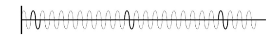
Figure 1: Example of solitary waves
2.2. Example of information allocation
We decided to use the interval between WSs of SW-TC as information. Figure 2 shows an example of information allocation of the SW-TC. Here we prepare 2 WSs and set the WS to a 25Hz sinusoidal waveform for the sake of clarity.
In Figure 2, there are 23 non-current spaces (broken dotted line) in one cycle excluding the 2 WSs (solid line). In the example at the third of Figure 2, there are non-current spaces of 3 waves and 20 waves between the 2 WSs, which is defined as (3:20) or (20: 3). However, (3:20) and (20:3) are considered the same allocation. The small intervals distance between the 2 WSs is defined as signal number (Signal No.), and in the above example, it is defined as Signal No.3. As a result, 11 types of information can be acquired in Figure 2.
If we set the WS to 3 WSs, the information quantity will increase significantly from 11 types to 70 types. In this way, the information quantity can be expanded by the number of WSs, and can be further expanded by increasing the frequency from 25Hz to 50Hz or 100Hz. There is no restriction on the shape of the WS, and it is possible to use a triangle waveform instead of a sinusoidal waveform.
Figure 3 shows an example of the Signal No. transmitted to the SW-TC of each track circuit. First, the state where the train exists on the track circuit and the signal current cannot be received is defined as Signal No.0. Next, the case where a train exists on the front track circuit is defined as Signal No.1, and Signal No. corresponding to the position of the front train is transmitted to the rear track circuit, as shown in Figure 3. Signal No.11 is transmitted to the track circuit that is more than 11 tracks away from the front train.
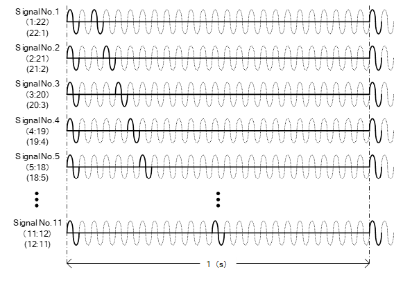
Figure 2: Example of information allocation
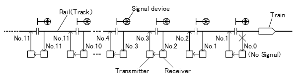
Figure 3: Example of information allocation
2.3. Enhancement by defining solitary wave frame
We have defined the solitary wave frame (SWF) so that SW-TC can be equipped with various functions except for the train position. The structure of the SWF is shown in Figure 4. In this paper, we assume that one SWF is configured at the position of 25WSs.
First, we defined 2 consecutive WSs as a starting element (SE) and placed it at the beginning of the SWF, and set the start position of the frame. If space is secured before and after the SE and one WS is assigned in the remaining positions, 21 types of information can be acquired. If 2 WSs are assigned, the information quantity increases to 190 types, and because of the effect of the SE, the information quantity of SW-TC increases significantly, and the function of SW-TC can be expanded.
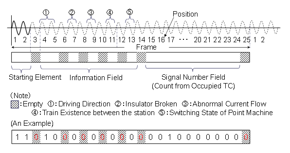
Figure 4: Structure of an SWF
Next, we defined the 4th-13th positions on the SWF as the information field. SW-TC can expand the function by assigning each position of the information field a function, however the details will be explained in the following chapters.
Finally, we defined the remaining 15th-24th positions on the SWF as the signal number field. When the state where the train exists on the track circuit, the 15th-24th positions are assigned 0. When the case where a train exists on the front track circuit, the 15th position is set. When the case where a train exists on the track circuit that is more than 9 tracks away, the 23th position is set. When a train is not exist on the track circuit at the station premises and a route related to that SW-TC is not set , the 24th position is set. Furthermore, in the SWF, there is a restriction that the WS of 2 consecutive waves are assigned only to the SE, and are not assigned in the information field and the signal number field.
3. Current Issue
3.1. Periodic inspection by track inspection car
The track circuit has an important role in detecting trains to ensure safe train operation. Thus, railway operators run inspection cars such as track inspection cars to regularly verify the condition of the tracks [19]. However, despite the inspection, there are still many railroad damages such as rail breakage, and if adverse conditions overlap, it may lead to dangerous accidents such as derailment. Furthermore, since inspection by a dedicated track inspection vehicle is expensive, and there are many small and medium-sized railway operators that cannot perform sufficient track inspections.
3.2. Condition monitoring by track circuit monitor
In the existing track circuit, preventive maintenance has been achieved by introducing a track circuit monitor, a condition monitoring system, etc., and constantly measuring the transmission/reception level of the track circuit. These track monitoring system must work in different weather conditions. Figure 5 shows an example of the screen of the track circuit monitor for the SMET (SMET monitor) of the train detection device for station premises.
The SMET monitor can display the reception level of each track circuit accumulated in the past, the leakage voltage of the adjacent track circuit, etc., which is effective in identifying the cause of a track circuit failure [20]. However, fluctuations in the transmission/reception level vary by track circuit or weather, and the technology for detecting signs of track circuit failure from the tendency of level fluctuations is not completely developed.
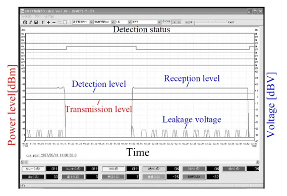
Figure 5: Sample of SMET monitor screen
3.3. Investing the cause with a dedicated measuring instrument
Currently, when an unexpected interruption in the track circuit occurs owing to a failure caused by the rail, in addition to measuring the voltage, a dedicated measuring instrument such as a search coil is used to measure the signal current flowing through the rail by walking on the site. Because there is a high possibility that some type of failure has occurred near the place where the current is changing, the investigation is conducted while grasping the current distribution, but it takes a considerable time to identify the cause and recover the track.
Furthermore, the signal and return currents flow in the track circuit, however, if a large return current flows in the left or right rails, the signal current is affected, and the track circuit becomes unbalanced. When track circuit becomes unbalanced, railway operators investigate the cause using a dedicated measuring instrument such as a return current measuring device. This device measures the return current flowing through the rail with a clamp-type current sensor and measuring device, as shown in Figure 6.
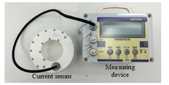
Figure 6: Return current measuring device
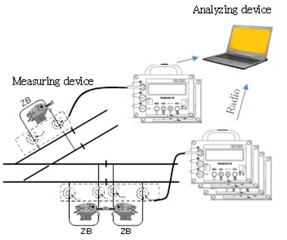
Figure 7: On-site measurement method
Figure 7 shows the on-site measurement method [21]. A current sensor and measuring device are installed on-site to measure the current flowing through the left and right rails. The measurement data are stored in a plurality of measuring devices, and the analyzing devices wirelessly collects the measurement data from the measuring devices in a batch, analyzes the data, and identifies the cause. However, it takes time and effort to investigate, such as installing devices at the site after a track circuit failure occurs, measuring data for a long time, and removing the devices from the site after measurements are completed.
4. Results and Discussion
In this chapter, we present that SW-TC can diagnose the insulation deterioration of the track circuit and detect the deterioration of the reception level. As a result, we explain that railway operators can identify signs of track circuit failure and improve maintainability using SW-TC. Furthermore, we also explain that SW-TC can also improve reliability, availability, and safety, compared to existing track circuits.
4.1. Insulation deterioration diagnosis of the track circuit
Ordinally, track circuits other than non-insulated track circuits have track insulation inserted to separate their boundaries [22]. When the insulation breakdown occurs at the boundary of the track circuit, if the track circuit current is short-circuited because of the train approaching, the current of the rear track circuit may wrap around and the track relay will operate, preventing the detection of the train. As a countermeasure, an orbital current with the phase inverted is passed through the rear track circuit, and when there is insulation breakdown regardless of the state of the train, the track relay is dropped, and the block signal is stopped. However, it is not easy to identify the faulty part in the field because the track circuit failure has various factors such as the insulation breakdown of the track circuit, failure of the receiving equipment, rail breakage, and failure of the track circuit transmission equipment. Figure 8 shows the track circuit boundary and track circuit transmission/reception equipment (TC-TRE). Ordinally, there is a dead section between the bonding points where the impedance bond is connected across the rail insulation, and no current flows. When insulation breakdown occurs at the boundary of the track circuit, leakage current flows in the dead section at the point where the track insulation is broken, and the faulty part can be detected by performing on-site measurements using a dedicated measuring instrument. However, during that time, the train cannot operate and maintenance personnel needs to move to the site.
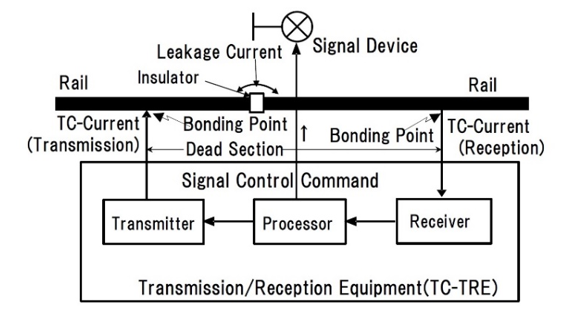
Figure 8: On-site measurement method
As SW-TC assigns SE to the beginning of SWF, if the track circuit insulation is broken, the rear track circuit current wraps around and is superimposed. As a result, the SE generation interval is disturbed in the receiving equipment of the track circuit. At this time, if the current transmission of the transmission equipment to the rear SW-TC is stopped, the wraparound and SE interval disturbance in the SWF are eliminated. The SW-TC can clearly detect the breakdown of the track circuit insulation even during operation by using this mechanism.
Figure 9 shows a deterioration diagnosis method for track insulation of the SW-TC using the principle of the track circuit boundary insulation breakdown detection. Ordinally, the received current input to the TC-TRE has a waveform of [Line No.1], as shown in Figure 9. For the transmission signal to the rear track circuit, an SWF of [Line No.2] is generated, indicating that the Signal No. shifts by one position. In fact, SW-TC transmits SWF at different timings after a certain offset time, as in [Line No.3].
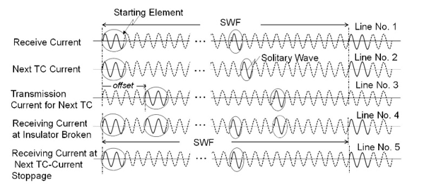
Figure 9: Fault detecting method at a broken insulator
If insulation breakdown occurs at the boundary of the track circuit in this state, SW-TC receives a signal that is a mixture of [Line No.1] and [Line No.3], in which two SEs exist in the SWF. This signal has a waveform similar to that of [Line No.4], and, as explained in section3 of chapter2, TC-TRE can detect insulation breakdown because only SE has two consecutive SWs in the SWF. At this time, if the transmission to the rear track circuit is temporarily stopped, the track circuit current waveform becomes [Line No.5], which is the same as [Line No.1], and the SW-TC can diagnose that the waveform disturbance is due to insulation breakdown. As a result, SW-TC can significantly reduce the time required to identify the insulation breakdown location of the track circuit, and improve maintainability.
Especially in the existing track circuit, railway operators need to measure the received signal level of the track circuit on a regular basis. On the other hand, the SW-TC can automatically performs maintenance measurement for each track circuit and request maintenance, so maintainability of the track circuit can be significantly improved.
4.2. Output of preventive maintenance information
The SW-TC obtains track signals based on the position of WS in SWF; therefore, even when the reception level drops, processing can be continued if the required solitary wave can be detected. However, it is thought that the decrease in the reception level eventually shifts to a state in which the solitary wave itself cannot be detected. Therefore, it is possible to request maintenance at an early stage by outputting the state in which the reception level has dropped as preventive maintenance information. As a result, SW-TC can automatically perform preventive maintenance measurements at the track circuit level and request maintenance while maintaining its function even when the reception level drops, and maintainability of the track circuit can be improved.
4.3. Transmission method
When the SW-TC detects failure sign information of insulation breakdown of the track circuit or deterioration of reception level, as shown in Figure 4, ② (7position: Insulator Broken) or ③ (9position: Abnormal Current Flow) of the in the SWF is set. With this track signal, it is possible to transmit preventive maintenance information via the crew, for example, by blinking the aspect of the block signal.
If the on-board device is mounted on the train, it can detect insulation breakdown or a decrease in the reception level of the track circuit by decoding the failure bit of the information field in the received SWF. With this information, for example, it is possible to turn on the LED of the on-board device and request maintenance.
4.4. Improved reliability
In the existing track circuit, in order to control block signal of multiple aspects, it was necessary to lay a cable and obtain the information of the forward block signal. On the other hand, SW-TC can obtain the necessary train location information with cableless, and can control block signal of multiple aspects. Furthermore, SW-TC is a simple configuration that eliminates the need for transformers, resistors, phase adjusters, etc., which are required depending on the type of existing track circuit.
With the existing D-ATC, it is necessary to install a large-scale ground equipment to generate digital telegrams and detect trains. On the other hand, SW-TC does not require ground equipment and can realize advanced train protection control equivalent to D-ATC, so significant cost reduction can be expected. Therefore, SW-TC can realize the same functions as the existing track circuit with a simple configuration, and thus the reliability is improved.
4.5. Improved availability and safety
In the field environment of an actual railway signal, the reception level of the track circuit signal fluctuates due to the influence of electric rolling stock current flowing in the track circuit and rainfall. Therefore, in the SMET, which is an existing digital track circuit, a highly reliable measure that follows changes in environmental conditions, such as automatic tracking of threshold levels, have been adopted and are effective. SW-TC judges reception based on the digital sampling data obtained by analog-to-digital (A/D) conversion. Therefore, SW-TC records the received waveform when adjusted at the time of installation as a template, and discriminates WS from the correlation between the received waveform and the waveform of the template. Furthermore, SW-TC can separate from noise by confirming the validity of the number of WS in one cycle.
SW-TC can filter noise judging the track circuit information based on the input waveform itself obtained through A/D conversion, not just the level, and confirming the validity such as the shape check of the isolated wave. As a result, it can improve the noise resistance performance, and reduce dangerous accidents due to disturbing waves, as compared with the existing track circuit method. In this way, the SW-TC can reduce the probability that the train will stop due to track circuit failure due to noise, and improves availability. Furthermore, safety can be improved by reducing dangerous accidents.
5. Conclusion
In this paper, we explained the principle of the SW-TC, and introduced application examples to realize preventive maintenance. The proposed SW-TC scheme can not only realize advanced train protection control equivalent to D-ATC, but also significantly improve maintainability compared to the existing track circuits by detecting failure sign information such as insulation breakdown and deterioration of the reception level. As a result, it can significantly reduce the cause identification and recovery time for railway operators when track circuit failures occur.
Track circuits are a proven technology that has ensured the safety for many years, however, in recent years, new train control signal systems that utilize radio have increased, and the systems tend not to use the track circuits. However, it is difficult for small and medium-sized railway operators to introduce a wireless train control system in terms of costs. The proposed SW-TC method is an extension of the existing track circuit, however, cableless and energy saving compared to the existing track circuit, and can realize advanced train protection control at a low cost. Furthermore, it has excellent reliability, availability, maintainability, and safety, its introduction effect is high, and it is a cheaper and more manageable system for small and medium-sized railway operators. SW-TC has the potential to continue to develop its functions, and we expect that the track circuit can be regenerated by using this method.
Conflict of Interest
The authors declare no conflicts of interest.
Acknowledgment
This research has been funded with a grant from Daido Signal co., Ltd. I would like to thank the three anonymous reviewers for their valuable suggestions for improvement.
- T. Terada, H. Mochizuki, H. Nakamura, “Development of New Track Circuits for Energy Conservation and Signal Control Innovation,” 2021 International Conference on Electrical, Computer, Communications and Mechatronics Enginnering (ICECCME2021), 1-5, 2021, doi:10.1109/ICECCME52200.2021.9591127.
- E. Itakura, Kidoukairo, Signal Safety Association of signal technology series of Japan, 1971.
- S. Egusa, Shingou niokeru system kaihatsu, Railway and Electrical Engineering of Japan, 2016.
- T. Kawano, M. Fukuda, Atarashii tougougata kidoukairo no kaihatsu, Japan Railway Engineer’s Association of Japan, 2012.
- Y. Hirao, “Safety Technologies on Railway Signalling and Functional Safety,” Fundamentals Review of Japan, 7(2), 124-132, 2013, doi:10.1587/essfr.7.124.
- S. Masutani, H. Utsumi, A. Minami, Scanning siki kidoukairo nitsuite, Railway and Electrical Engineering of Japan, 2011.
- A. Minami, Y. Youda, T. Suga, Ressya kenti souti (SMETgata), Daido signal corporation quarterly publication of Japan, 2003.
- T. Mizuno, T. Yamamoto, Shingoukiki no shou energy ka no torikumi, Railway and Electrical Engineering of Japan, 2016.
- T. Terada, Y. Matsuwaki, T. Fuse, A. Minami, H. Mochizuki, H. Nakamura, “Regeneration of Track Circuit and a Proposal for a New Signal Control System,” The transactions of the Institute of Electrical Engineers of Japan.D, 141(3), 206-211, 2021, doi:10.1541/ieejias.141.206.
- N. Terada, Digital ATC, Railway and Electrical Engineering of Japan, 1998.
- T. Igarashi, K. Tashiro, Digital ATC system niokeru RAMS kikaku heno taiou, Railway and Electrical Engineering of Japan, 2004.
- T. Takashige, kiki bunsangata ATC (digital ATC), Railway and Electrical Engineering of Japan, 1993.
- H. Nakamura, Hoan setsubi no sugata to tenbou, Railway and Electrical Engineerig of Japan, 2012.
- M. Matsumoto, S. Kitamura, D. Watanabe, Zairaisen digital ATC niokeru assurance gijutsu, Railway and Electrical Engineering of Japan, 2001.
- M. Fukuda, H. Arai, Ressya no anzenunkou wo sasaeru gijutsu, Railway Technical Research institute of Railway Research Review of Japan, 2010.
- M. Fukuda, Kishikata Yukusue, Railway Technical Research institute of Railway Research Review of Japan, 2012.
- H. Arai, N. Terada, Singou Ressyaseigyo gijutsu no Hensen to Doukou, Railway Technical Research institute of Railway Research Review of Japan, 2015.
- H. Nakamura, Recent Trends of ICT Application to Railway Operation and Signaling Systems: The Innovation of Railway Signaling Systems, Information Processing Society of Japan, 2014.
- M. Matsumoto, “Trend of Sensing Technology on Railway Operation,” The transactions of the Institute of Electrical Engineers of Japan.E, 127(11), 461-466, 2007, doi:10.1541/ieejsmas.127.461.
- T. Senoo, Ressya kenti souti (SMETgata) you monitor souti, Daido signal corporation quarterly publication of Japan, 2007.
- T. Noguchi, M. Suzuki, T. Kobayashi, The development of new measuring device of return current, Technical review of JR East of Japan, 2015.
- A. Taguchi, “Improvement of Border Characteristics of Jointless Track Circuit,” The transactions of the Institute of Electrical Engineers of Japan.D, 118(2), 243-252, 1998, doi:10.1541/ieejias.118.243.