Antenna System Design To Increase Power Transfer Efficiency with NFC Wireless Charging Technology

Adv. Sci. Technol. Eng. Syst. J. 7(3), 123–128 (2022);
 DOI: 10.25046/aj070314
The NFC wireless charging feature is an extension of the NFC technology that can be implanted on wearables. The purpose of this paper is to show how to increase power transfer efficiency on both transmitter and receiver antenna systems. To demonstrate this problematic, firstly this paper gives an overview of how this NFC feature is implemented (architecture, power transfer, carrier frequency, communication bandwidth…), and can be complementary to Qi technology. Then, it provides a study on how to improve the power transfer efficiency on the antennas. To perform this result, the designer can adapt some antenna parameters as coupling coefficient, quality factor, matching method, and the antenna size. If these recommendations are respected, the power transfer efficiency between the antennas could reach between 70% and 80% with the NFC charging technology.
1. NFC Technology Overview
The NFC technology is initially used for contactless communication to exchange data. It is present in wearable applications such as authentication, payment, ticketing, pairing… However, these wearables are mechanical constraints because they embed a lot of components in a limited space. Moreover, for the wearables to be waterproof, and to avoid overheating issues, mechanical links (such as buttons or charger ports) must be removed, which leads to the use of wireless charging technology for batteries. To answer these problematics, a first paper was published [1], which described this new wireless charging technology as a solution.
The NFC wireless charging feature can use the same architecture (antenna, EMI filter, matching circuit, and NFC chip) as the NFC communication feature in order to operate [2]. So, a designer can use both NFC features on the same product [3].
Furthermore, the NFC antenna is a benefit to use NFC wireless charging in targeted devices. Indeed, since antennas are not standardized, they can take every possible size as shown on Figure 1. On the other hand, they do not have to be used with ferrite. So, the wearables that cannot use the Qi charging due to its features, like these standardized antennas with its ferrite, they can use the NFC wireless charging feature. Hence, all products can use wireless charging technology.
Nevertheless, the NFC technology has benefits and drawbacks. The issues that exist in NFC communication feature are also present in NFC charging feature. The main challenge for an NFC product is to be interoperable with other NFC devices available on the market because of their very characteristics, such as the antenna shape, waveform signal, or power signal. To avoid compatibility issues, the designer must check whether the new product, with its feature-related requirements, is compliant with the different existing standards: for instance, ISO 14443, NFC Forum, and EMVCo [4].
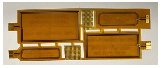
Figure 1: NFC wireless charging antenna with different sizes
Another issue is related to the NFC wireless charging, which was standardized only recently. The NFC Forum developed the standard for NFC charging at the end of 2021 to standardize the communication protocol, power supply, and product behavior in relation to issues such as foreign object detection [5]. This means that the products developed and marketed before this standardization operates with a proprietary mode.
The aim of the NFC wireless charging feature is to provide an alternative to Qi charging so that the user can benefit from better power transfer efficiency. This article describes this new wireless charging process and gives some recommendations to optimize the power transfer efficiency between the transmitter and receiver antennas, which is where the highest power losses occur.
2. NFC Wireless Charging Architecture
The NFC wireless charging feature is a radio frequency technology like NFC communication feature. It is based on a transmitter and a receiver, show on Figure 2.
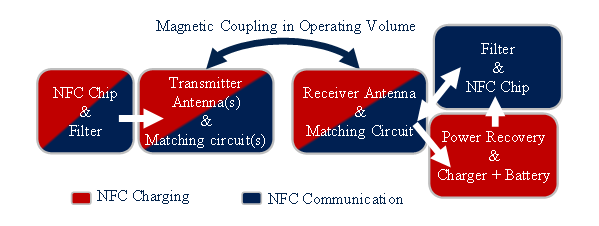
Figure 2: NFC wireless charging architecture
The transmitter uses the same architecture to perform both NFC features. It consists of:
- One NFC chip with its filter circuit, which provides power, and processes the exchanged data.
- One or two antenna(s) with its(their) matching circuit(s).
The difficulty on the transmitter board is on the matching circuit. Indeed, the calibration is different for the two NFC features [6]. So, to increase the power transfer efficiency, the transmitter must be matched in operating mode. This functionality is further described in part III.
On the other hand, to optimize the communication distance, the transmitter must be matched in the open-air mode (there is no metal object and/or antenna in the PCD’s operating volume).
In this paper, we chose to use the same antenna and two different matching circuits to address both features.
The receiver, for its part, is composed of one antenna to receive the power and/or data signal with its matching circuit. The matching must be done in open air mode (without metal object in operating volume of the transmitter). Then, this antenna is connected to two different circuits:
- The NFC wireless charging circuit. It consists of a power recovery, in this architecture a diode bridge is used, and a charger chip with a battery.
- The NFC communication circuit. It consists of an EMI filter and an NFC chip to process the exchanged data.
The new NFC wireless charging uses a carrier frequency of fr=13.56MHz, as shown on Figure 3, which also gives the power limit that the device must not exceed. Indeed, the device must not generate a signal with carrier frequency higher than 60dBµA/m. Moreover, the power limit decreases with communication data rate (ΔF).
Furthermore, to enhance the power transfer efficiency, the system quality factor, Q, must be as high as possible. But, to optimize the communication bandwidth, the system quality factor must be limited.
So, if the transmitter and receiver use one antenna, it is important to find the best tradeoff in terms of quality factor to have the best power transfer efficiency sent, according to the resonance frequency fr, and to allow good communication, according to the bandwidth ΔF, between the two boards as shown on (1) and Figure 4.
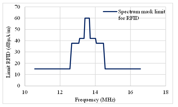
Figure 3: Power limit for RFID transmission
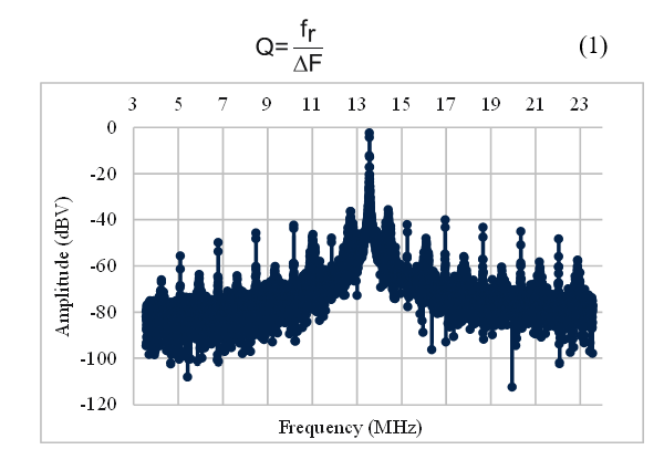
Figure 4: NFC signal with a quality factor allowing both NFC feature
The NFC Forum standardized the power transfer used for NFC charging. They indeed give several power classes as shown in Table 1. This power transfer is guaranteed at the receiver end, and the standard provides the maximum power as an indication. A designer can use this technology at higher power [7]. Moreover, we can see that NFC charging targets a lower power than the Qi power class shown in Table 2.
Table 1: NFC wireless charging power classes given by the NFC Forum.
| Power Classes | Minimum Power | |
| Power Transfer | Class 0 | 250 mW |
| Class 1 | 500 mW | |
| Class 2 | 750 mW | |
| Class 3 | 1000 mW |
Table 2: Qi wireless charging power classes given by the WPC.
| Power Classes | Power | |
| Power Transfer | BPP | 5000 mW |
| EPP | 15000 mW |
3. Optimization of antenna parameters to increase NFC power transfer efficiency
The purpose of the NFC wireless charging feature is to obtain best power transfer efficiency [8]. In order to reach this goal, it is important to mind one critical area, delimited by the transmitter and the receiver antennas themselves and the space between them. The power losses are indeed greatest in this area, and this is where the designer can increase the overall power transfer efficiency.
The Figure 5 shows the used boards to perform the test given on this chapter. The Figure 6 shows a block diagram of NFC wireless charging use to find the result exposed on this chapter.
The first parameter to increase the power transfer efficiency is to put the same antenna size on the transmitter board and the receiver board [9]. Furthermore, since this new technology is used in small devices, the selected antenna must be smaller than the size of the targeted wearable. For the tests described in this article, we used the class 6 antenna as the reference antenna for the transmitter and receiver board, as shown on Figure 7. This is the smallest antenna given by the ISO standard [10].
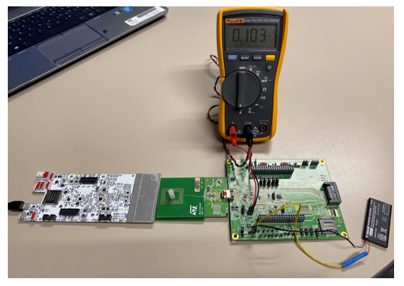
Figure 5: Power transfer efficiency measurement on test board
Therefore, if the transmitter’s reference antenna is used in front of different receiver antenna sizes, as shown in Table 3, we can see, on Figure 8, the impact of the antenna design on the power transfer efficiency between the coupled antennas. The results show that the best efficiency is achieved when the PCD and PICC antennas are identical.
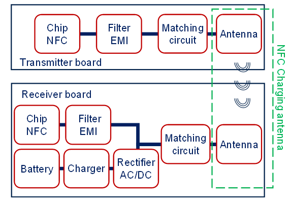
Figure 6: A block diagram of an NFC wireless charging system
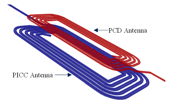
Figure 7: Transmitter and receiver antennas coupled
Table 3: Antenna design used for the different tests.
| Receiver antenna size | Length | Width |
| Class 6 max size | 25 mm | 20 mm |
| Bigger than transmitter antenna | 49 mm | 30 mm |
| Smaller than transmitter antenna | 20mm | 20 mm |
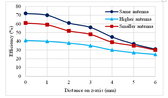
Figure 8: Power transfer efficiency simulated between the PCD and PICC antennas according to the distance along the z-axis
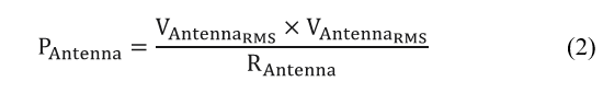
We can split the power losses between both transmitter and receiver antennas into three parts. The first two losses are on the real part of the PCD and PICC antenna impedance. To quantify these P_antenna losses, we measured the RMS voltage V_Antenna across the antennas. We then divided the measured value by the equivalent parallel resistance of the antenna, R_antenna, as shown on (2).
The last loss is between the antennas due to the coupling coefficient. To decrease the impact of this parameter, the designer must use the same form factor antenna. Thus, the coupling coefficient k increases as shown on (3) [11]. It uses the equivalent radius of both the receiver (R_Rec) and transmitter R_Trans antenna. The two antennas are centered on a single x-axis.
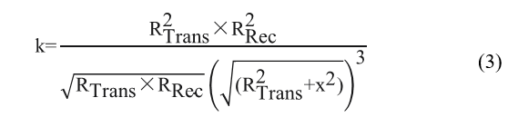
Figure 9 shows that, if we use the three receiver antenna shapes (defined in Table 3) in front of the transmitter with the reference antenna, the power transfer efficiency for a given coupling coefficient is better with the “same antenna” configuration.
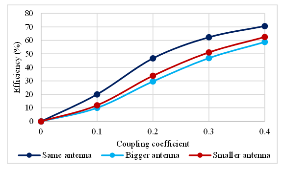
Figure 9: Power transfer efficiency simulated according to the coupling coefficient between the two antennas
The last antenna parameter that a designer can adjust to optimize the power transfer efficiency of the antenna is the antenna quality factor. Indeed, this parameter characterizes the resonance model and allows both the transmitted and received signal amplitudes to be increased [12]. Figure 10 presents the impact of the antenna quality factor at transmission (Tx) and reception (Rx) on power transfer efficiency. However, for the NFC communication use case, the transmitter and receiver quality factor must be adapted to keep a bandwidth large enough not to filter the data signal. The bigger the communication rate is, the smaller the transmitter and receiver quality is. In classical products, the transmitter and receiver quality factor are between 5 and 20.
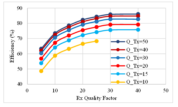
Figure 10: Impact of the quality factor on power transfer efficiency
In addition to the antenna parameters, the designer must keep in mind two other methods to optimize the power transfer efficiency. The first one is the space between both the transmitter and receiver antennas [13]. As announced in part II, both NFC feature use the same architecture. However, the operating volume is different. It is few centimeters for NFC communication whereas it is limited to only a few millimeters for NFC charging. To increase the performance, it is therefore preferable to reduce the operating volume to the location where the receiver receives the most power from the transmitter. Choosing this method also allows the transmitter and receiver boards to be in the matching position, and to increase the coupling coefficient. This again increases the power transfer efficiency.
To perform this test, a custom operating volume is created. Class 6 antennas are used on both transmitter et receiver for this test as shown on Figure 11.
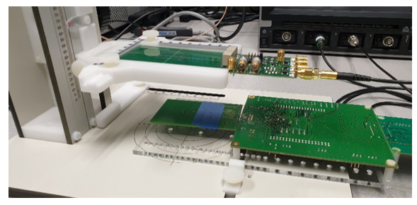
Figure 11. Operating volume test bench
Figure 12 shows power transfer efficiency curves in the custom operating volume. Initially both antennas are centered, and we apply a x offset for different z height. We can see that the power transfer efficiency is spatially limited to just a few millimeters or a single position.
The second method used to increase the power transfer efficiency even more, is to match the transmitter in operating mode. To perform this calibration, the receiver antenna is placed in operating volume of the transmitter antenna, where it receives the most power. Now, the transmitter is set up to send the maximum power when the receiver is near to it. This again shows that maximum power is delivered at the position where the matching takes place and reduces the operating volume to a static position.
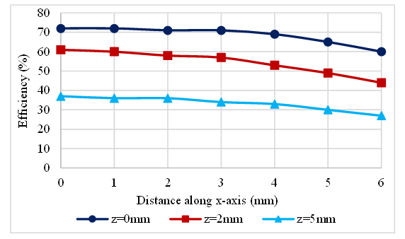
Figure 12: Power transfer efficiency in the operating volume according to the x- and z-axes
With this calibration method, the coupling effect has no more impact. Indeed, when the receiver antenna (L_Rec) is brought closer to the transmitter antenna (L_Trans) which leads to the detuning of the transmitter because the mutual inductance (M) changes as shown in (4). Because of this phenomenon the transmitter is no longer optimized to send maximum power [14]. It is why the transmitter must be matched in operating mode.
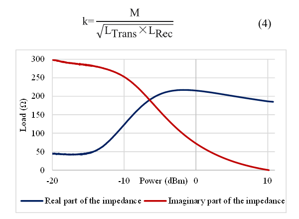
Figure 13: Diode bridge nonlinearity impact on the PICC impedance
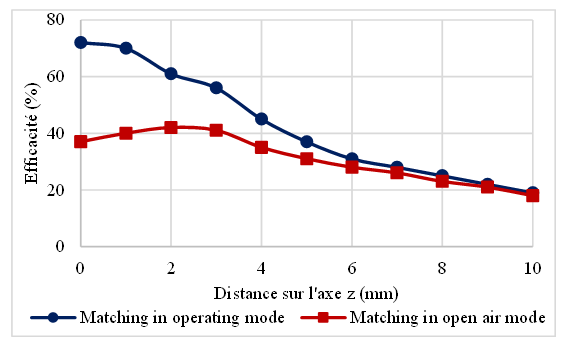
Figure 14: Power transfer efficiency depending on the matching mode
After determining the transmitter matching position, the designer must consider a second parameter to match the transmitter: the diode bridge non-linearity. Indeed, this parameter implies that the receiver impedance varies depending on the power that passes through it, as shown on Figure 13. To consider this nonlinearity, the designer must match the transmitter when it charges the receiver. Figure 14 shows the power transfer efficiency between both transmitter and receiver antennas with the impact of the matching mode used on the transmitter antenna.
4. Conclusion
This paper gives the architecture used by the NFC wireless charging feature. This technology is used to charge the embedded batteries in wearables. The designer can use the NFC products already available on the market to perform NFC charging. It must update the protocol to the new NFC Forum standard on both transmitter and receiver boards.
In addition to this protocol update, this article shows how to reach an optimized power transfer efficiency on the antennas. The results exposed in this article give the antenna parameters (antenna design, coupling coefficient, quality factor) and two additional methods (matching mode and operating volume) that a designer must pay attention to optimize the power transfer efficiency. If the advices are respected, the efficiency on antenna class 6 can reach between 70% and 80%.
Conflict of Interest
The authors declare no conflict of interest.
Acknowledgment
I would like to thank the co-authors who helped me in the writing of this paper with their patience, advice and experience. I would also like to thank the STMicroelectronics proofreading service for improving the English level of this paper.
Finally, I thank the ANRT organization which allowed the feasibility of my PHD in link with the laboratory IM2NP and the company STMicroelectronics.
- J. Quignon, A. Tornambe, T. Deleruyelle and P. Pannier, “Wireless charging using NFC technology,” 6th International Conference on Smart and Sustainable Technologies”, 1-4, 2021, doi: 10.23919/SpliTech52315.2021.9566468.
- S. Kolev, “Designing a NFC system,” 56th International Scientific Conference on Information, Communication and Energy Systems and Technologies, 111-113, 2021, doi: 10.1109/ICEST52640.2021.9483482.
- H. Shibuya, T. Tsukuda, H. Suzuky, T. Shimizu, M. Dobashi, S. Nishizono, M.Baba, H. Sasaki, K. Terajima, “A wireless charging and near-field communication combination module for mobile applications,” 64th Electronic Components and Technology Conference, 763-768, 2014, doi: 10.1109/ECTC.2014.6897371.
- N. S. S. Shobha, K. S. P. Aruna, M. D. P. Bhagyashree and K. S. J. Sarita, “NFC and NFC payments: A review,” International Conference on ICT in Business Industry & Government, 1-7, 2016 doi: 10.1109/ICTBIG.2016.7892683.
- NFC Forum “Technical specification wireless charging version 2.0,” 2021.
- L. Li, Z. Gao and Y. Wang, “NFC antenna research and a simple impedance matching method,” Proceedings of 2011 International Conference on Electronic & Mechanical Engineering and Information Technology, 3968-3972, 2011, doi: 10.1109/EMEIT.2011.6023890.
- https://www.nucurrent.com/nfc-wireless-charging-explained/ Accessed on January, 2022.
- M. Watanabe and K. Akatsu, “A study of high electrical power and high efficiency antenna in 13.56 MHz Wireless Power Transfer,” Energy Conversion Congress and Exposition, 1027-1031, 2020, doi: 10.1109/ECCE44975.2020.9235829.
- B. Couraud, T. Deleruyelle, R. Vauche, D. Flynn and S. N. Daskalakis, “A Low Complexity Design Framework for NFC-RFID Inductive Coupled Antennas,” IEEE Access (Volume 8), 111074-111088, 2020, doi: 10.1109/ACCESS.2020.3001610.
- ISO/IEC, 14443, “Cards and security devices for personal identification _Contactless proximity objects,” 2018.
- K. Finkenzeller, RFID Handbook: Fundamentals and Applications in Contactless Smart Cards, Radio Frequency Identification and Near-Field Communication, 1999.
- P. Baumgartner, O. Biro, W. Renhart, R. Torchio, C. Riener, C. Koger, T. Bauernfeind, “PEEC based design optimization of NFC antennas considering the full system quality factor,” Tenth International Conference on Computational Electromagnetics , 1-4, 2019 doi: 10.1049/cp.2019.0123.
- W. Lee, J. Kang, J. Lee, Y. -J. Hong, J. Suh and S. J. Kim, “A Compact Base Station System for Biotelemetry and Wireless Charging of Biomedical Implants,” Asia-Pacific Microwave Conference, 339-341, 2019, doi: 10.1109/APMC46564.2019.9038396.
- M.Meiller, Impact of antenna design tune and match on wireless range, High Frequency Electronics, 2015.
No related articles were found.