Optimization of the Sliding Mode Control (SMC) with the Particle Swarm Optimization (PSO) Algorithm for Photovoltaic Systems Based on MPPT
Volume 7, Issue 1, Page No 100-106, 2022
Author’s Name: Ilhem Bouchrihaa), Ali Ben Ghanem, Khaled Nouri
View Affiliations
The Laboratory of Advanced Systems LSA, Polytechnique School, University of Carthage, Tunis, 3200, Tunisia
a)whom correspondence should be addressed. E-mail: ilhem.bouchriha@gmail.com
Adv. Sci. Technol. Eng. Syst. J. 7(1), 100-106 (2022); ![]() DOI: 10.25046/aj070110
DOI: 10.25046/aj070110
Keywords: Boost converter, Maximum Power Point Tracking, Sliding Mode Control, Particle Swarm Optimization

Export Citations
Photovoltaic systems are classified as non-linear systems. On the other hand, the characteristics of photovoltaic cells are non-linear. For this reason, researchers use several methods of maximum power monitoring (MPPT) to improve the performance of photovoltaic system. It is therefore necessary to use an adaptation stage between the photovoltaic generator (GPV) and the load to take out at any time the maximum power available of the GPV and to transfer it to the load. This stage acts as an interface between the two elements by ensuring the transfer of the maximum power supplied by the generator using a control system used for this purpose. This work described a study on two Maximum Power Point Tracking (MPPT) techniques, classic sliding mode control (SMC) and particle swarm optimization (PSO) for controlled boost chopper. The decisive simulation results that by applying the PSO and the conventional SMC to a well-built model, the PSO achieves high precision results compared to the sliding mode control. In fact, we have suggested a new MPPT method based on the optimization of the command parameters in sliding mode by the PSO optimization algorithm.
Received: 20 September 2021, Accepted: 25 January 2022, Published Online: 21 February 2022
1. Introduction
The integration of renewable energies into power generation systems is becoming important, especially with the increase in the world’s population and technological advancement. Solar energy is considered a renewable energy source with great potential and widely distributed geographically. Its drawback remains the high initial cost of implementing the system [1], [2]. To make a photovoltaic system more profitable, an method for finding the maximum power point tracking MPPT is released to command a DC-DC converter placed between the photovoltaic panels and the load, what is called the adaptation step [3] [4]. The objective of this algorithm is to maximize the energy extracted of the solar panels, and thus growth the overall performance of the system.
Besides, and because of the strongly nonlinear electrical characteristics, many researchers have proposed control solutions whatever the climatic conditions [5].
Several researchers have worked on the MPPT method as in [6-8] they have shown that the technique founded on fuzzy logic control (FLC) can quickly go along with the point of MPP. In [9], we studied the sliding mode control (SMC) and compared it with the P&O algorithm we concluded that this method is more robust and faster. We also found that they worked on the backstepping method but they improved it in [10] we combine it with the artificial neural network (ANN) method [11]. This gave us a good performance in maximum point tracking. Indeed, the first work on the evolution of Sliding Mode Control for DC-DC converters introduced in 1983 [6] and 1985 [9]. This work shows how SMC can be used in different topologies of second order DC-DC converters. The concept of fetching the equivalent command to the duty cycle in order to obtain a sliding mode controller controlled by PWM can be found in [6]. A general SMC synthesis method applicable to most DC-DC converter topologies is proposed by [5] which shows that SMC allows greater robustness to variations in load and circuit parameters.
This method appears more adequate and gives a good transient response. On the other hand, many works propose the control of the duty cycle rather than directly controlling the state of the transistor ensuring the commutation and this without degrading the properties of the controller. In this case, the discontinuous command is replaced by the equivalent command [12]. The latter can be assimilated to the duty cycle since we are working at high frequency. The advantages of this method are that it does not require additional circuits and that the transient response remains good.
This work is an extension of the work initially presented in International Conference on Advances in Science, Engineering and Technology 2021(ICASET) [2]. In this article, the MPPT control of the photovoltaic system is processed under varying climatic irradiation.
The photovoltaic system is composed a photovoltaic panel, boost chopper, MPPT controller and resistive load.
This paper describes a study of the two MPPT techniques, this is firstly the SMC (sliding mode control) method and the second is the PSO (particle swarm optimization) algorithm. Then we optimize the parameters of the SMC using the PSO algorithm. The two proposed techniques are implemented on the Boost converter with MATLAB.
In the following, we will first present a model of a photovoltaic panel. Then modeling a DC-DC step-up converter as a linear switching system. Next, we will describe the two MPPT commands SMC and PSO. And finally our contribution is the combination between the two methods to improve the performance of the sliding mode method. The results of the simulation are presented in the last part.
2. Modeling of the proposed system
A photovoltaic PV system is a set of elements of electricity production. Our system is shown in Figure 1. These components are essentially the PV, a boost chopper and the command MPPT.
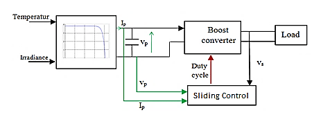 Figure 1: PV System
where:
Ip: the output currents of the photovoltaic panel (PV).
Vp: the output voltage of the PV.
Vs: the output Voltage of the DC/DC converter.
3. PV Array
The electric model of a solar cell consists of one or two diodes in parallel and a series resistor Rs supplied by an ideal current source, the first diode D1 describes the semiconductor properties of the cell and the second D2 models the phenomenon. Recombination of charge carriers. We have, this time, two diodes for the phenomena of polarization of the PN junction and two resistors. When the surface of the PV cell is exposed to light, it absorbs light energy and turns directly into electric current. The voltage generated can vary between 0.3V and 0.7V depending on the aging of the cell, the temperature of the material used and the sunshine. The operation of a solar cell can be described by considering the equivalent electrical schema below figure 2 [13-15].
 Figure 2: Diagram of the model equivalent to two diodes of a PV cell.
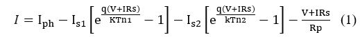 Knowing that: I and V are the current and output voltage of the photovoltaic cell. Id1 and Id2 are the saturation currents of the diodes. d1 and d2 are the diode factors. Iph is the photo generated current, it is often given by.
 With : S is a Sunstroke. T is the temperature of the cell in Kelvin. From these equations, it is evident that the characteristic I-V strongly depends on insolation and of the temperature. Temperature dependence is further amplified by saturation currents inverse of the diodes which are given by:
where Eg is the gap energy of the semiconductor and k1, k2 having the following values.
K1=1,2A/cm2.K3
K2=2,9.105A/cm2.K5/2
To confront our model a little more with reality, it is necessary to study how these parameters will influence the characteristics of the cell. The figure 3 and 4 presents the curves of I and P in function of V, for different levels of sunshine at constant temperature, and for different temperatures with constant sunshine.
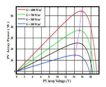 Figure 3: Power curves of PV module at various temperatures simulated with the MATLAB model Boost converter
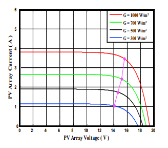 Figure 4: Curve of the current as a function of the voltage of a PV panel at various solar radiations simulation with MATLABC
4. Boost converter
The DC / DC converter makes it possible to connect the PV field to a DC bus, to which the various energy machines of the system are connected to the load. A chopper can be realized using an electronic switch which can be controlled on opening and closing, such as GTO thyristors or bipolar or insulated gate field effect transistors operating in switching mode. The principle of a chopper consists in establishing and then periodically interrupting the source-load connection using the electronic switch. This must be able to be closed or opened at will in order to have an adjustable continuous output voltage. Our Boost chopper is shown in the figure 5.
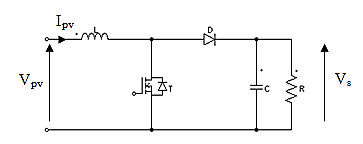 Figure 5: BOOST converter
Table 1 shows the nominal parameters of the circuit. Throughout the duration dTs of the switching period Ts, the switch is closed and the diode is off. The current increases until it reaches the peak value in the inductor. When the thyristor is blocked, the diode will be conductive, the current will decrease until it reaches its minimum value and the output voltage equals the input voltage.[16]
Table 1: The Value of the Boost Chopper Coefficient
| Symbol | Description | Value |
| Vpv | Input voltage | 220v |
| F | Switching Frequency | 50Hz |
| C | Capacitance of capacitor | 2000.10-6 |
| L | Inductance | 0.3μH |
| R | Load resistance | 50Ω |
The energy accumulator in the coil is dissipate into the capacitor and the load. In the interval , the switch T is shut and the diode is off. We obtain:

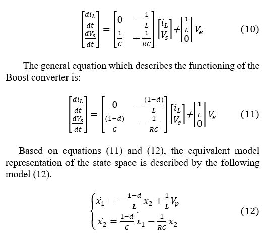
The second configuration is described by the following linear model:
5. MPPT control strategy
PV systems are classified as nonlinear systems. Indeed, researchers have proven that simple commands and PID correctors are effective for linear systems. But for nonlinear systems sometimes the PID correctors are not sufficient. This is why we are always looking for other methods to have good precision and the system will be more stable and robust [17], [18].
5.1 Sliding mode control (SMC)
The variable structure controls by the sliding mode, which appeared in the 1960s, due to the research of the mathematician A.F. Philipov, is a more nonlinear method fonder on the use of discontinuous expressions. After the work developed by the team of Professor Emelyanov in the Soviet Union and due to problems with chatter and implementation, the variable structure control is obtained in the late 1970s. It has appeared well in the fields of electronics and computing. Indeed, this command is based on a high frequency switching for a better sliding speed [19]-[21].
The principle of operation of the SMC method is to bring the system of states to arrive at the sliding surface and switch it by a suitable logic switching round it until the point of equilibrium, hence the sliding phenomenon [22]. The form of a variable structure command can be given by:
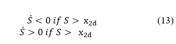
where: S is the output voltage.
Equation 14 defines the path of the first order system. And so, the speed of convergence will be controlled.
When we do the combination of equation 14 with the two equations 12 and 10, we get the duty cycle equation d which allows us to tune the output of our system. d will be the duty cycle of our boost chopper.
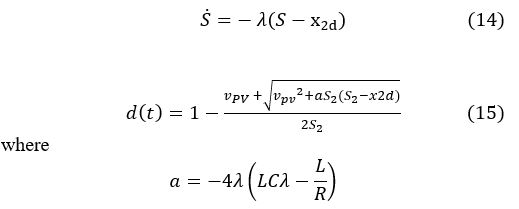
where
Our command described by equation (15), is show in the Figure 6.
 Figure 6: Sliding Mode Control Matlab/SIMULINK
The SMC is characterized by its simple design and robustness regardless of the types of disturbance. The best features of this approach are:[22], [23]
- The classification of the switching principle introduced us to a dynamic comportment of the system.
- In closed buckle, the response is unfeeling to the types of perturbations and to changes in parameters.
- Choice of a fairly large area according to the case. It’s faster while still having the opportunity to grow in an unstable state.
5.2 Particle Swarm Optimization (PSO)
Particle Swarm Optimization is a biologically inspired method for solving optimization problems. Like artificial neural networks, genetic algorithms, or ant colony algorithms, the PSO is a bio-inspired algorithm.
The objective function of the PSO algorithm has been defined as the power delivered by our PV system.
The equations (15) and (16) represent the movement of particles through each iteration of the program and its objective functions (fitness) are calculated to be capable to measure the best position of all the Pg.
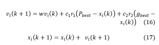
where k is the number of iterations, i The number of the particle, is the speed of the particle at the precedent step, is the new value the studied velocity of the particle, c1 and c2 are positive parameters specific to cognitive actions and to the algorithm of individual social particles, r1 and r2 are taken randomly between [0,1], is the better position acquired by the measured element in the objective function, is the better position obtained amongst all the particles evaluated in the objective function, w presents to an inertial mass which directly affects the current velocity of the particle with respect to the rate which precedes [24], [25].
The updating of the Pb and Pg is carried out at each iteration as described by the organization chart of Fig.4. The steps are repeated as long as the stopping criterion is not reached.
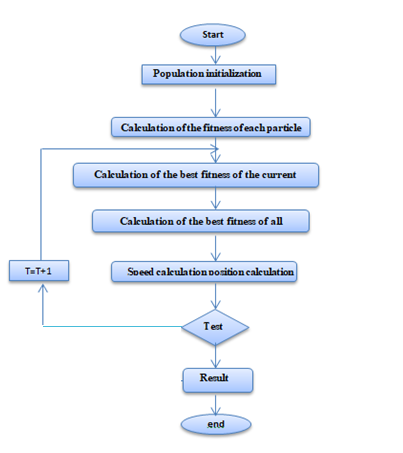 Figure 7: Flowchart for the PSO algorithm.
- Stage I: Initialize coefficients c1 and c2, the inertia coefficient (w).
- Stage II: Random construction of the initial particle group and calculation of the fitness of each element (Pbest): better position of the number i in the current group; (Pgbest): Better positioning in all group (best of the best).
- Stage III: Based on the formula, we again calculate the velocity and location of each particle.
- Stage IV: In the current state, we calculate the best fitness of the group and compare it with the last one to have the better of all the groups ().
- Stage V: Increment K by 1 so k = k+ 1.
- Stage VI: If the stop condition is obtained, we go to the 7th step. Other, go back to stage III.
- Stage VII: the optimal solution will be saved in ()
 Figure 8: Block diagram of the PSO-SMC method
5.3 The Proposed PSO-SMC Controller
This part presents the sliding mode method to optimize with the evolutionary algorithm PSO as seen previously the SMC method can be better improve its performance, the parameters (S, ) can be obtained using the PSO algorithm. After initialization the values of the particles. Our PSO algorithm tests the search space based on equations (16) and (17). Each particle keeps its best position () which will be compared each time with the best position of the other particles. And finally, to have a minimum value of objective function, the optimal parameters are Soptimum and optimum [26].
6. Simulation Results and Discussion
To know the stability and follow the dynamic response of our two MPPT methods: SMC and PSO. We implemented the model of our PV system proposed in the MATLAB / Simulink. We vary the irradiations and with a constant temperature equal to 25°C [27].
Table 2: The parameters of the PSO method
| Parameters | Values |
| C1 | 2 |
| C2 | 1.8 |
| W | 0.8 |
| Kmax | 10 |
| Number of particles | 3 |
Figure 9 and Figure 10 shows the simulation results of the two tested methods. Figure.10 present the output voltage value and the Figure.9 present the power of boost chopper.
The simulation showed us that the SMC method gave us an acceptable result from a stability point of view. But if we compare it with the PSO method we find it more efficient and faster. And for that we are going to combine the two methods together and we will find the result in the figure 11. We notice that the PSO-SMC method is correct our new method and faster and stable and more exact folds as shown in the table.
 Figure 9: Optimum power of the PV system for varying conditions of irradiation
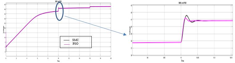
Figure 10: Optimum voltage of the PV system for varying conditions of irradiation.

Figure 11: Optimum power of the PV system for varying conditions of irradiation

Figure 12: Optimum voltage of the PV system for varying conditions of irradiation
Table 3: Comparison of MPPT techniques
| Algorithm | PSO | SMC | PSO-SMC |
| Complexity | Low | Low | Low |
| Setting Time ts | 10.034 | 10.044 | 10.034 |
| Peak time tp | 10.011 | 10.005 | 10.011 |
| D | 2.726 | 7 | 5 |
7. Conclusion
In this article we worked on a photovoltaic system controlled by two techniques PSO and SMC. After comparative with the two methods, the PSO is very robust in relation to SMC. So, we have optimized the parameters of the SMC by the PSO algorithm to obtain a new SMC-PSO method. We can conclude that the SMC method when combined with PSO has become faster and more stable.
- J. Sedo, S. Kascak, “Control of single-phase grid connected inverter system,” ELEKTRO 2016 – 11th International Conference, Proceedings, 207–212, 2016, doi:10.1109/ELEKTRO.2016.7512066.
- I. Bouchriha, A. ben Ghanem, K. Nouri, “A Comparison of Sliding Mode Control and Particle Swarm Optimization for Photovoltaic System under Partially Shaded Condition,” Undefined, 310–314, 2020, doi:10.1109/IC_ASET49463.2020.9318254.
- E. Fossas, A. Ras, “Second order sliding mode control of a buck converter,” Proceedings of the IEEE Conference on Decision and Control, 1, 346–347, 2002, doi:10.1109/CDC.2002.1184516.
- A. Al-Gizi, S. Al-Chlaihawi, A. Craciunescu, “Efficiency of Photovoltaic Maximum Power Point Tracking Controller Based on a Fuzzy Logic,” Undefined, 2(3), 1245–1251, 2017, doi:10.25046/AJ0203157.
- E.M. Zakaria, S.H. Arafa, M.N. Fahmy Nashed, S.G. Ramadan, “Fuzzy Logic Control Management with Stand Alone Photovoltaic – Fuel Cell System,” Undefined, 5(1), 424–430, 2020, doi:10.25046/AJ050154.
- V.I. Utkin, “Sliding Modes in Control and Optimization,” Sliding Modes in Control and Optimization, 1992, doi:10.1007/978-3-642-84379-2.
- S.Z. Hassan, H. Li, T. Kamal, M. Nadarajah, F. Mehmood, “Fuzzy embedded MPPT modeling and control of PV system in a hybrid power system,” in 2016 International Conference on Emerging Technologies (ICET), IEEE: 1–6, 2016, doi:10.1109/ICET.2016.7813236.
- S.Z. Hassan, H. Li, T. Kamal, U. Arifoğlu, S. Mumtaz, L. Khan, “Neuro-Fuzzy Wavelet Based Adaptive MPPT Algorithm for Photovoltaic Systems,” Energies, 10(3), 394, 2017, doi:10.3390/en10030394.
- Y. Jung, J. So, G. Yu, J. Choi, “Improved perturbation and observation method (IP&O) of MPPT control for photovoltaic power systems,” Conference Record of the IEEE Photovoltaic Specialists Conference, 1788–1791, 2005, doi:10.1109/PVSC.2005.1488498.
- K. Sundareswaran, V. Vignesh kumar, S. Palani, “Application of a combined particle swarm optimization and perturb and observe method for MPPT in PV systems under partial shading conditions,” Renewable Energy, 75, 308–317, 2015, doi:10.1016/J.RENENE.2014.09.044.
- K. Chennoufi, M. Ferfra, “Fast and Efficient Maximum Power Point Tracking Controller for Photovoltaic Modules,” Undefined, 5(6), 606–612, 2020, doi:10.25046/AJ050674.
- V. Repecho, D. Biel, J.M. Olm, E. Fossas, “Sliding Mode Control of Power Converters with Switching Frequency Regulation,” Studies in Systems, Decision and Control, 115, 385–409, 2018, doi:10.1007/978-3-319-62896-7_16.
- S.Z. Hassan, “Hermite-Wavelet Based Intelligent MPPT Adaptive Control Paradigm for PV in a Standalone/Grid Connected Hybrid Power System,” MS Thesis, COMSATS Univeristy, Pakistan, 2014.
- S.Z. Hassan, S. Mumtaz, T. Kamal, L. Khan, “Performance of grid-integrated photovoltaic/fuel cell/ electrolyzer/battery hybrid power system,” in 2015 Power Generation Systems and Renewable Energy Technologies, PGSRET 2015, 1–8, 2015, doi:10.1109/PGSRET.2015.7312249.
- T. Kamal, S.Z. Hassan, M.J. Espinosa-Trujillo, H. Li, M. Flota, “An optimal power sharing and power control strategy of photovoltaic/fuel cell/ultra-capacitor hybrid power system,” Journal of Renewable and Sustainable Energy, 8(3), 035301, 2016, doi:10.1063/1.4948926.
- A. Jouila, K. Nouri, “Applications to function approximation and system control based on wavelet networks,” 2017 18th International Conference on Sciences and Techniques of Automatic Control and Computer Engineering, STA 2017 – Proceedings, 2018-January, 426–431, 2018, doi:10.1109/STA.2017.8314864.
- A. Jouila, K. Nouri, “Stabilization of Neuro-Control Structure using Lyapunov Functional Based Approach,” 2019 International Conference on Signal, Control and Communication, SCC 2019, 81–86, 2019, doi:10.1109/SCC47175.2019.9116173.
- S. Jebri, K. Nouri, L. Bouslimi, “Speed tracking control performance with frequency and amplitude dependence,” Proceedings of International Conference on Advanced Systems and Electric Technologies, IC_ASET 2017, 454–459, 2017, doi:10.1109/ASET.2017.7983736.
- A. Azzabi, K. Nouri, “Design of a robust tracking controller for a nonholonomic mobile robot based on sliding mode with adaptive gain:,” Https://Doi.Org/10.1177/1729881420987082, 18(1), 2021, doi:10.1177/1729881420987082.
- M.G. Villalva, J.R. Gazoli, E. Ruppert Filho, “Modeling and circuit-based simulation of photovoltaic arrays,” 2009 Brazilian Power Electronics Conference, COBEP2009, 1244–1254, 2009, doi:10.1109/COBEP.2009.5347680.
- A. Azzabi, K. Nouri, “Design of a robust tracking controller for a nonholonomic mobile robot based on sliding mode with adaptive gain,” International Journal of Advanced Robotic Systems, 18(1), 2021, doi:10.1177/1729881420987082.
- J. Sedo, S. Kascak, “Control of Single-Phase Grid Connected inverter system,” in: J. Sedo and S. Kascak, “, eds., in 11th international ELEKTRO Conference, Strbske Pleso, Slovakia, 2016, doi:10.1109/ELEKTRO.2016.7512066.
- A.H. Alqahtani, V.I. Utkin, “Self-optimization of photovoltaic system power generation based on sliding mode control,” IECON Proceedings (Industrial Electronics Conference), 3468–3474, 2012, doi:10.1109/IECON.2012.6389342.
- L. Hang, S. Liu, Z. Lu, M. Castilla, “A novel robust sliding mode controller for Half-bridge converter,” 2010 International Power Electronics Conference – ECCE Asia -, IPEC 2010, 1618–1621, 2010, doi:10.1109/IPEC.2010.5543578.
- H. Renaudineau, F. Donatantonio, J. Fontchastagner, G. Petrone, G. Spagnuolo, J.P. Martin, S. Pierfederici, “A PSO-based global MPPT technique for distributed PV power generation,” IEEE Transactions on Industrial Electronics, 62(2), 1047–1058, 2015, doi:10.1109/TIE.2014.2336600.
- M. Arsalan, R. Iftikhar, I. Ahmad, A. Hasan, K. Sabahat, A. Javeria, “MPPT for photovoltaic system using nonlinear backstepping controller with integral action,” Solar Energy, 170, 192–200, 2018, doi:10.1016/J.SOLENER.2018.04.061.
- K. Nouri, R. Dhaouadi, N.B. Braiek, “A New Adaptive Control Scheme Using Dynamic Neural Networks,” Undefined, 20(1), 171–177, 2008, doi:10.20965/JRM.2008.P0171.
Citations by Dimensions
Citations by PlumX
Google Scholar
Crossref Citations
- Habiba Rizki, El-Mahjoub Boufounas, Aumeur El Amrani, Mohamed El Amraoui, Lahcen Bejjit, B. Benhala, A. Lachhab, A. Raihani, M. Qbadou, A. Sallem, "Performance Enhancement of a Solar Photovoltaic System with Differential Evolution-Optimized Quasi Sliding Mode Control." E3S Web of Conferences, vol. 601, no. , pp. 00064, 2025.
No. of Downloads Per Month
No. of Downloads Per Country