A Study of Stirling Engine Efficiency Combined with Solar Energy

Adv. Sci. Technol. Eng. Syst. J. 6(2), 837–845 (2021);
 DOI: 10.25046/aj060297
Fossil fuel can no longer supply the constantly spiking demands of energy around the world, hence the increasing research on renewable energies as an alternative. The Stirling Engine is an external combustion engine, giving us a wide range of heat sources: solar, nuclear. The Stirling engine makes best of use of solar sources in an environmentally friendly way. It has no emissions and live longer as compared to Photovoltaic cells. The Stirling engine can operate at Low Temperature difference, which makes it prominent. In order to study the efficiency of a conversion from thermal energy to work, we need to take into account the energy efficiency, which is a key parameter in Low Temperature Difference Stirling Engine, even if its efficiency is lower than those of high temperature Stirling engine. In this article, we are studying the efficiency of the Stirling engine as a first step using a parabolic mirror to focus the sun’s radiation onto the engine. In this article, we are studying the efficiency of the Stirling engine as a first step, by making isothermal and adiabatic analysis of the engine to detail the operation throughout its process, and be able to act on the various input parameters that impact the value of the final yield, and in a second step, using a parabolic mirror to focus the sun’s radiation onto the engine.
1. Introduction
Solar energy is an energy that falls into the category of renewable energies, because it is considered inexhaustible. Technologically, two ways are practiced in the use of direct solar energy; solar thermal energy and Photovoltaics. Regarding the solar thermal, it’s a system that uses solar energy to produce heat by heating a fluid at more or less high temperature. We can therefore produce energy, like the case of classical thermal power stations. In this case, we are talking about thermodynamical central power plants. As to the Photovoltaics, it is a system which is composed of photovoltaic cells. It directly converts a part of solar rays to electricity with photovoltaic effect. A solar powered Stirling engine is a type of external combustion engine, which uses the energy from the solar radiation to convert solar energy to mechanical energy. The resulting mechanical power is then used to run a generator or alternator to produce electricity. Initially, Stirling engine was invented by Robert Stirling in the year 1816 [1].
Solar power generation could be accomplished using various methods, such as linear Fresnel systems, Parabolic through Solar tower systems, and most importantly Solar dish systems (Figure 2), which happen to be one of the most intuitive and efficient ways of concentrating solar heat on the receiver that drives the Stirling engine-generator unit. It is applied in several situations. Due to the available sizes of Stirling engines, this method is most useful in small capacity cases that do not exceed tens of kW.
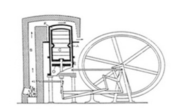 Figure 1: Stirling Engine. [1]
Furthermore, we are studying the efficiency of the Stirling engine and comparing it with existent internal combustion engines to see if it is worth using it as an alternative. Furthermore, we are going to study the possibility to combine the Stirling engine with solar energy for a more environmental-friendly solution.
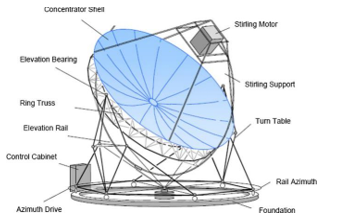 Figure 2: Design of the EURODISH System. [2]
Engine operation
A Stirling engine is a piston engine operating on the general principle of the Stirling cycle. The Stirling cycle and engine were defined in 1989 by the international scientific community as [3]:
“A Stirling cycle is defined as a process that occurs in any closed space containing a working fluid in which changes in volume induce cyclical changes in pressure of the fluid and its displacement in the closed space induce changes in cyclic temperatures in the fluid.”
The Stirling engine offers the possibility of having one of the best efficiencies with less emissions unlike internal combustion engines. Its older models are less efficient and huge, but the current models are more developed, which improves efficiency, as well as the use of any external heat source for very high temperatures [4].
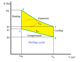 Figure 3: Stirling engine cycle. [1]
The theoretical Stirling cycle is similar to the Carnot cycle, except that the in th Stirling cycle the isochoric processes replace the adiabatic heating and cooling processes of the Carnot cycle. The Stirling cycle then involves four successive evolutions of an ideal gas between two heat sources that has constant temperatures Tc and Te, which in turn are separated by a perfect exchanger which has an isochoric process. When applying the first principle of thermodynamics, we get the same efficiency as the Carnot cycle [4].
The thermodynamic cycle can be plotted on a PV diagram that represents the variation of the pressure versus the volume. (Figure 3).
In a theoretical case, this thermodynamic cycle can be split into four reversible processes (Figure 3).
23: (heat transfer from an external source to the working fluid). The cold cylinder piston (the working piston) is at the top of its downstroke, while the hot cylinder piston (the expansion piston) is in the middle of its upstroke; the expansion piston moves down, while the working piston remains stationary. This is the engine time; the hot source supplies the gas with thermal energy, and the descent of the expansion piston drives the crankshaft. On the theoretical indicator diagram, this cycle time corresponds to curve 2-3. As the volume of the gas increases and its temperature is constant, the pressure of the gas in the hot cylinder decreases.
34: (heat transfer from the working fluid to the regenerator). The last stroke being completed, the cycle is returned to its initial state, the mechanical coupling between the two pistons is such that the working piston begins to rise, while the expansion piston goes down; during this double movement, the gas being hot, it gives up its heat to the regenerator and the gas cools as it passes from one cylinder to another. As its volume remains constant, its pressure decreases; which is represented by segment 4-3 of the theoretical diagram. The engine has returned to the starting point, the regenerator is ready to absorb heat again, and a new cycle can begin again.
41: (heat transfer from the working fluid to the cold source). the ingenious coupling between the pistons allows the expansion piston to be stationary while the working piston descends. The gas is compressed, but its temperature does not increase, because the compression takes place in the cylinder connected to the cold source. Energy is rejected to the cold source and the compression is isothermal; this time is represented by curve 4-1 on the theoretical indicator diagram.
12: (heat transfer from regenerator to working fluid) The expansion piston goes up and the working piston goes down, which allows the movement of the gas from the hot side, without changing the volume; segment 1-2 of the theoretical diagram is therefore vertical. Passing through the regenerator, the gas recovers the heat that was stored there and, at the same time, returns this element to its initial temperature. [1]
During this cycle, the system releases an amount of energy, which is needed later to heat the fluid, and restart the cycle as a loop.
Robert had the idea to use a regenerator to recover the transferred energy and then use it for heating. Ideally, the curve is elliptic, hence all amounts of energy are recovered (Figure 4).
We mostly find Stirling Engines in one of the three common configurations which are α, β and γ.
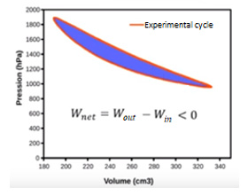 Figure 4: Stirling cycle curve. [1]
Alpha-type Stirling Engine
The α-type engine is composed of two separated cylinders (Figure 5). The two cylinders are exposed, respectively, to a hot and a cold temperature source. And to each cylinder, is sealed a “hot” piston and a “cold” piston. contains two separate power pistons in separate cylinders, a “hot” piston and a “cold” piston. It also has a pipe that connects the two cylinders. This pipe is usually filled by a regenerative material in order to enhance the thermal efficiency.
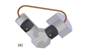 Figure 5: Alpha-type Stirling engine. [5]
F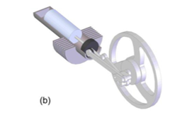 igure 6: Beta-type Stirling engine. [5]
Beta-type Stirling Engine
In contrast with the α-type, β-type engine is composed of one unique cylinder with one piston sealed to it, and a displacer as shown in Figure 6. At the top of the cylinder, is placed a heat source, and a cold source at the bottom. The gas flow through the small clearance between the cylinder wall and the displacer; when it flows towards the hot end of the cylinder, then the expansion process occurs, and when it flows towards the cold end, then the compression process occurs . It is the displacer that allows the gas to move between the cold zone and the hot zone. The system is linked to a flywheel.
Gamma-type Stirling Engine
The γ-type engine is similar to a β-type engine, the main difference is that the cooling chamber is mounted in a separate cylinder as demonstrated in Figure 7, but it is still connected to the same flywheel.
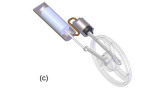 Figure 7: Gamma-type Stirling engine. [5]
Comparison between the three types
To make a comparison between the 3 types of architectures, the compression rate must be defined: The compression rate r_v is defined here as the ratio of the maximum volume VM by the minimum volume Vm that it will occupy during this same cycle:
![]()
For given hot and cold source temperatures, and for identical displacements, Alpha engines have higher compression ratios than those of type Beta, which in turn are slightly higher than those of Gamma engines. This has the consequence of being able to extract more power from an Alpha engine because it will run more quickly. The downside is that they require more design and manufacturing rigor.
Advantages and disadvantages
Advantages
Quiet operation: In contrast with internal combustion engines, there is no relaxation in the atmosphere. With that absence of gas that will eventually escape, plus the absence of the open-close valves, this engine is quiet and has a reduced mechanical stress.
High efficiency: Stirling engines have the best efficiency compared to an internal combustion engine, and it could even exceed 40 % as efficiency.
The multitude of possible “hot springs” and ecological aptitude: Due to its heat supply method this engine can operate from any heat source.
Reliability and easy maintenance: The technological simplicity of this engine allows engines to be very reliable and require little maintenance.
The long service life: Due to its simplicity, the life of this engine is, in theory, longer than that of conventional engines. Indeed, it requires less maintenance and its replacement is much faster and less dangerous.
Reversible operation: The Stirling cycle is reversible, when a Stirling engine is driven by another engine; it becomes a heat pump capable of working in cooling and heating mode.
Disadvantages
The price: The main drawback of this engine is its manufacturing cost, which is about twice that of a diesel engine. Stirling engines require inlet and outlet heat exchangers, which contain the high temperature working fluid, and must withstand the corrosive effects of the heat source and the atmosphere.
Lack of flexibility: Quick and efficient variations in power are difficult to achieve with a Stirling engine. This is more suitable for running at constant nominal power. This point is a big handicap for the automotive industry.
Height and weight: External combustion, which requires heat exchangers at both hot and cold spots, makes the Stirling engine generally bigger in size and heavier than a generic internal combustion engine with the same power output.
Advantages of Stirling engine compared to an internal combustion engine
In comparison with a combustion engine, Stirling engine overtakes it on many levels, for example we can look at fuel flexibility; A Stirling engine does not require a highly refined liquid to operate, it can use a variety of liquid and gases, which makes it more flexible than a Diesel engine that required refined Diesel fuel. And because of the external-combustion process of the Stirling engine, it also burns any given fuel cleaner than an internal-combustion engine. In addition, Stirling engines can be balanced mechanically, making them less noisy by eliminating the mechanical vibration problems. On the other hand, internal-combustion engines have severe noise because of the periodic nature of their combustion and mechanical motion processes. We can enhance them to be more silent, by using mechanical isolation and acoustic design, but this would increase the cost of the engine, and would make it unpractical in some situations. [6].
Applications of the Stirling engine
Besides the academical use of the Stirling Engine, we can find this technology in various daily useful applications. The American Stirling Company offers one of these applications which is the wood stove Stirling fan (Figure 8): A silent fan that does not need electricity to move the heat from a wood stove, and have more heated area in the house instead of having only a restricted heated area near to the wood stove.
Another interesting application of the Stirling engine is the Combined Heat and Power systems (CHP) that can be very useful in businesses such as a commercial laundromat, since it generates electricity and utilizes the waste energy produce heat. There is also a smaller version of CHP systems, called micro CHP that have residential use [7].
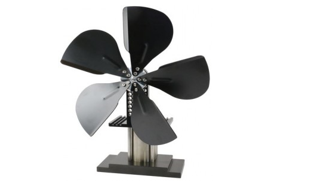 Figure 8: The Stirling stove fan by American Stirling Company. [8]
The SAAB company [9], which is a Swedish company specialized in building submarines, uses the Stirling engine in their Gotland and Södermanland submarines classes, essentially because the Stirling engine is silent compared to Diesel engines. SAAB claims that the secret to their world’s most silent submarine is Stirling engine based submarines do not need to surface and recharge the batteries, using the air-independent propulsion [9].
Enhancement of the Stirling Engine performance
To act on the Stirling engine performance, we are led to optimize the temperature of the cold and hot sources, to obtain an optimal temerature difference. We can also modify the geometry of the engine to keep the losses to an absolute minimum.
The role of the regenerator is to recover the heat from the cooling of the gas to heat it again. It therefore plays a key role in the operation of the engine.
Thus, it seems legitimate to seek to optimize the operation of the regenerator to improve that of the engine.
The MOD II automobile engine [10] that was produced in the 1980’s [10] was among the most efficient Stirling engines, it reaches a maximum efficiency of 38.5% [10] , compared to a petrol engine which has a yield of (20-25%).
It was abandoned due to high development costs and fears of not being able to compete with internal combustion engines in terms of reactivity.
To reach a high efficiency in a Stirling engine we are led to use a regenerator; imperfect heat transfer that occurs between the engine and the source may lead to external losses of energy as well as internal losses.
The efficiency of an engine varies with the operating speed due to the different losses interactions
Modeling of the Stirling Engine
Efficiency Stirling engine:
r_v : Volume Ratio
λ : Temperature Ratio
S: Entropy
Cv : The molar heat of gas
T_i : Inlet temperature to Urieli’s generalized cell
P_i : The pressure at a given time I
T_(c ): Compression temperature
T_ck : mean temperature of working fluid at cooler and compression space
T_e ∶ Temperature at expansion side
T_d : Temperature at dead space
T_he : Temperature of working fluid at heater and expansion space.
T_k : Temperature of working gas at cooler.
V_c : Compression cylinder volume variation
V_d : Dead space volume
V_e : Expansion cylinder volume variation
V_r : Regenerator volume
w_c : Compression work
w_d : Work done from engine
w_e : Expansion work
w_s : West number
T_max: Maximum cycle temperature
T_min: Minimum cycle temperature
X : Distance
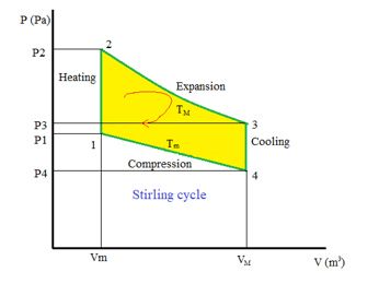 Figure 9: Stirling engine cycle. [1]
As the PV diagram for Stirling cycle shows (Figure 9):
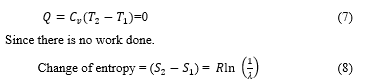
41: The engine is operating with a minimum value temperature during the isothermal compression. And with a constant energy:
With the provided heat (Q) = Recovered work (W_c)
12 : In the isochoric heating phase, both the compression piston and the expansion piston moving respectively towards the regenerator and away from the regenerator, simultaneously, keeping volume between the two pistons constant. The working fluid is flows from the compression area to the expansion area, making its temperature gradually increasing from Tmin to Tmax. This gradual increase of the fluid temeprature while it pass through the regenerator creates a gradual increase of pressure. There is no work done and there is an increase in the entropy and the internal energy of the working fluid.
The volume remains constant throughout this process.
With ? referring to the energy ratio defined by [11].
The provided heat Q will then be equal to:
23: The temperature is constant during the isothermal relaxation, while the volume increases as well as the entropy. There is no change of energy.
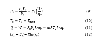
34: No work is provided during the isochoric cooling, the volume is constant.
The provided heat will then be equal to RT_2Ln(r_v) ) and the released heat will be equal to RT_4Ln(r_v).
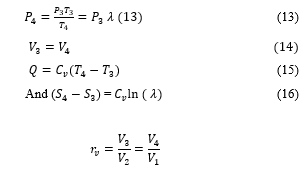
We can write the output as follows:
We then find the ideal Carnot efficiency that corresponds to the possible maximum theoretical efficiency in a two heat sources engine.
Isothermal analysis
According [12], we can obtain an efficient heat transfer by assuming that the total mass of the working gas inside the engine remains constant:
![]()
And considering that the pression in all of the engine is constant, and:
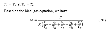
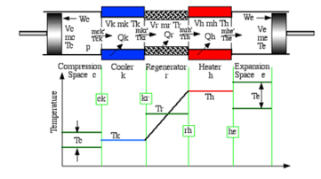 Figure 10: Ideal isothermal model. [13]
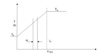 Figure 11: Linear profile of regenerator temperature. [13]
Then we can numerically define the assumption that the temperature profile is linear, by the equation of a straight line
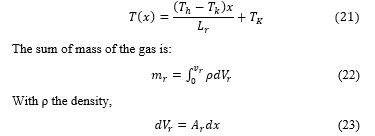
Where dx is the derived volume for a constant free flow area, and
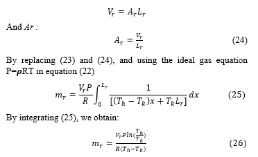
The definition of the regenerator effective average temperature (T), in terms of ideal gas equation:
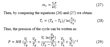
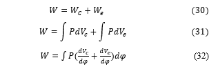
The total work of the cycle is the sum of the work of compression and expansion.
Isothermal modeling
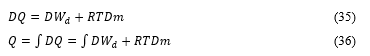
To study the heat transfer, it is primordial to consider the energetic equation of ideal gas.
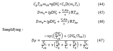
In [14] the author’s has modeled a generalized workspace cell, and as shown in Figure 12, it can be reduced to a workspace cell or a heat exchanger cell.
The enthalpy transfer out the cell (resp. into the cell) occurs with a mass flow rate m_0 at temperature T_0 (resp. a mass flow rate m_i at temperetaure T_i). The derivative operator is noted D and D_m refers to the mass derivative (d_m/ d_t).
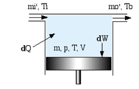 Figure 12: Generic cell diagram of the engine. [14]
The energy equation of the cell can be written as:
Heat transfer rate in the cell + Net enthalpy converted in thecell
=Rate of work applied on the environment + Rate of increase of internal energy in the cell.
![]()
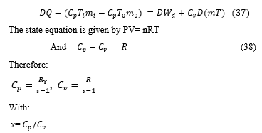
where C_p and C_v are respectively the specific heat capacities of gas at constant pressure and constant volume. The equation below is the well-known classical form of the energy equation in which the terms of kinetic energy and potential energy have been neglected.
Then :
![]()
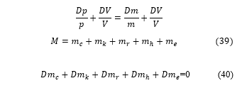
For reasons of mass conservation, the difference m_0-m_i is simply the rate of mass accumulation inside of the cell
R= C_p-C_v
Therefore, we can write the equation as:
Adiabatic modeling
The principle of this method uses a numerical resolution approach, it divides the volume of the engine into a certain number of control volumes, then it applies conversion equations to the momentum of the gas associated with its equation of state. The properties of the gas are considered uniform in each control volume. The interaction between volumes is taken into account when solving differential equations which is done simultaneously.
The complexity of the system to be solved and the calculation time depend on the assumptions used.
The adiabatic model is a model developed by [12] who used the work of [11]. In this model, the Stirling machine is divided into five control volumes, including two variables compression and expansion. The volumes of the cold and hot exchangers and of the regenerator are considered constant. The assumptions used are as follows:
Thermodynamic compression and expansion transformations are adiabatic,
The gas pressure is uniform throughout the machine,
He movement of the piston and of the displacer is sinusoidal,
The working fluid follows the ideal gas law,
The machine rotation speed is constant
The energy equation is applied to a generalized whole can be written as:
 By taking the logarithm on both sides of the equation and differentiating them, we get a differential form of the equation of state:
 Since the volume and the temperature are constant, the differential equation is shortened to:
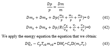
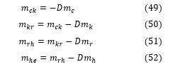
However, the compression space is adiabatic, 〖DQ〗_c=0, plus the realised DW_c= pDVc, for continuity reasons, the accumulation rate of gaz Dm_c is equal to the mass difference of the gas given by m_ck.
We consider the continuity equation, given by:
![]()
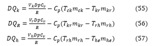
We apply successively the equation above to each of the cells as shown in the figure:
The total work done by the engine is the algebraic sum of the work done by the compression and expansion areas:
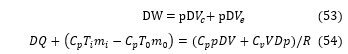
Dans les espaces d’échangeur de chaleur, aucun travail n’est effectué, car les volumes respectifs sont constants.
The actual Stirling cycle engine is subject to heat transfer, internal heat losses and mechanical friction losses, to estimate hese losses [15] defined certain engine temperature ratios.
The ratio of the lower operating temperature to the upper operating temperature of the engine is defined by: £ =T_k/T_e ;
The ratio of the cooler temperature to the heater temperature is defined as: € = T_c/T_h ;
The ratio of the expansion area temperature to the heater temperature is noted as: ₴ = T_e/T_h . with α=b/a and β= β=c/a, heat transfert coefficients.
Therefore, the average energy of the cycle is expressed by:
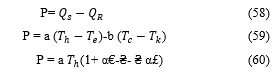
The thermal efficiency must not exceed the efficiency of the Carnot cycle.
This condition can be expressed as:
₴ ((α+1) Ϩ-β(1- Ϩ)^2)≧ α€+ Ϩ (61)
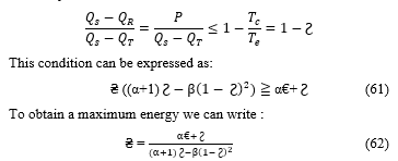
By replacing (62) in (60)
The maximum power is:
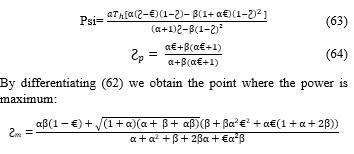
In [16] the author’s has proven that the maximum of the values that we can obtain are independent of the regenerator’s conductance value, and thus in the case of a uni-dimensional model of a Stirling engine.
Simulation and results
Now once we have characterized the engine geometrically, were all set to implement the isothermal model. The flow diagram in Figure 13 illustrates the steps of the model; we first use as an entry parameter the total mass of the initial engine m and an effective average pressure p.
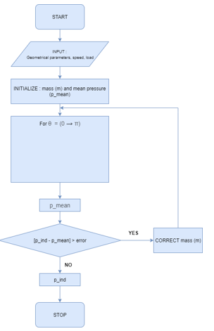 Figure 13: Isothermal model diagram.
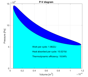 Figure 14: Pressure-volume diagram.
The algorithm then, for each value of θ, calculates the total average pressure as a function of the initialized mass m, and compares it with the reference pressure we defined at first. The algorithm iterate this comparison until we have convergence, i.e. the difference between the average pressure and the reference pressure is lower than the error.
The indicated work of the cycle is the obtained.
W = 1.9822 J
In Figure 14 we observe that the curve is closed and cyclical, and in each cycle, the work is obtained by calculating the area inside the curve, while the area below the curve is the heat absorbed during that cycle. The thermodynamic efficiency is the ratio of the work on the amount of heat absorbed
Conclusion
The article studies the efficiency and the uses of the Stirling engine, and relies on the process of transforming renewable thermal energy into mechanical work. Renewable thermal energy is available at low cost for the long term and enviroment friendly. Such engine relying on this process is certainly interesting, even if it has a low thermal efficiency.
We have seen how the Stirling engine’s perks can be used in different situations; it can be more advantageous than internal-combustion engine. Especially, at low maximum temperature and low temperature difference, the Stirling engine has virtually no substitute.
We can enhance the thermal efficiency by manipulating the shape of the displacer, the heat exchanger, the crank angle or use lf other working fluids. Stirling engine research and enhancements stimulate green education and can help reduce global warming and emissions.
This article is a first part of an modeling and simulation with MATLAB SIMULINK which will have as objective the improvement of the efficiency of the engine based on the difference of temperature, all while working on a concrete model.
- P. Gras, Le moteur Stirling et autres moteurs à air chaud, Decoopman Sciences & Techniques, 2010.
- R.M. Muthusivagami, R. Velraj, R. Sethumadhavan, “Solar cookers with and without thermal storage—a review”. Renewable and Sustainable Energy Reviews, 14(2), 691-701, 2010, doi: 10.1016/j.rser.2008.08.018
- P. Stouffs, “Machine thermique non conventionnelles:état de l’art, application, problème à résoudre,” Journée d’étude de SFT (France), octobre 1999.
- B. Kongtragool, S. Wongwises, “Investigation on power output of the gamma-configuration low temperature differential Stirling engines”. Renewable Energy, 30(3), 465–476, 2005, doi: 10.1016/j.renene.2004.06.003.
- A. Abuelyamen, Rached Ben-Mansour, “Energy efficiency comparison of Stirling engine types (α, β, and γ) using detailed CFD modeling’’, International Journal of Thermal Sciences, 132, 411-423, 2018, doi: 10.1016/j.ijthermalsci.2018.06.026.
- T. J. Marciniak, J. C. Bratis, A. Davis, and C. Lee. “An Assessment of Stirling Engine Potential in Total and Integrated Energy Systems’’ US . DEPARTMENT’ OF ENERGY, 1979.
- S. Murugan n , Bohumil Horák , “A review of micro combined heat and power systems for residential applications’’ Centre ENET, VSB Technical University, 17. Listopadu, Ostrava 708 00, Czech Republic
- American Stirling Company, www.stirlingengine.com
- Daniel Nilsson, Senior Develoment Engineer SAAB, “Development of the Stirling AIP system’’, UDT 2020 Energy&Propulsion.
- N. Lanciaux, Contributionau développement d’un moteur Stirling, de la cogénération dans le bâtiment à l’autonomie énergétique, PhD Thesis Université d’Évry-Val d’Essone, 2015.
- G. Schmidt “Classic analysis of the functioning of the Stirling engine”. A report publishedin German Engineering Union, XV; 1871.
- I. Urieli, D.M Berchowitz , “Stirling cycle engine analysis”. UK: Adam Hilger Ltd; 1984.
- M. T. García , E. C. Trujillo, J. A. Vélez Godiño and D. S. Martínez, “ThermodynamicModel for Performance Analysis of a Stirling Engine Prototype”, Energies, MDPI, Open Access Journal, 11(10), 1-25, 2018
- C.J. Rallis, “A new ported constant volume external heat supply regenerative cycle”. in 12th Intersociety Energy Conversion Engineering Conference, 1977.
- J.R Senft , “Theoretical limits on the performance of Stirling engines”. Int J Energy Research, 22(11), 991–1000,1998.
- D. Boer PCT, “Maximum obtainable performance of Stirling engine and refrigerators”, Journal of Heat Transfer, 125(5), 911-915, 203ASME J Heat Transfer 2003, doi: 10.1115/1.1597618.