
Using Formal Methods to Model a Smart School System via TLA+ and its TLC Model Checker for Validation
Volume 6, Issue 2, Page No 821-828, 2021
Author’s Name: Nawar Obeidata), Carla Purdy
View Affiliations
College of Engineering and Applied Science, University of Cincinnati, Cincinnati, OH 45221-0030, USA
a)Author to whom correspondence should be addressed. E-mail: obeidanh@mail.uc.edu
Adv. Sci. Technol. Eng. Syst. J. 6(2), 821-828 (2021); ![]() DOI: 10.25046/aj060295
DOI: 10.25046/aj060295
Keywords: TLA+, Verification and Validation, Safety

Export Citations
Formal methods are one of the efficient tools to verify and validate designs for different kinds of systems. Smart systems are attracting researchers’ attention due to the rapid spread of new technologies all over the world. Modeling a smart system requires connecting heterogeneous subsystems together to build it. Our contribution to this work is in focusing on using formal methods to prove that a design model meets its specifications. We have chosen to design a smart school building system due to the lack of research in this particular area, and to prove that formal methods are appropriate for different systems applications. In this paper, we have used UML diagrams and the formal specification language TLA+ to design a smart school building system. We validate our design using the TLC model checker. The smart school system has many subsystems connected together including a secure access system, lighting control system, climate control system, and smoke detection system. Safety is a very important attribute in this system. Our goal is to have a smart system that satisfies its functional requirements as well as any non-functional requirements like safety. The system provides safety for employees and students in the smart school.
Received: 25 December 2020, Accepted: 24 March 2021, Published Online: 04 April 2021
1. Introduction
Smart systems that have been designed and modeled by researchers include a smart school [1], smart library [2], a smart office [3], a smart home [4], and a smart campus [5]. The main focus of these systems was on safety and the ability to achieve specific goals. This paper is an extension of work originally presented at the 2020 IEEE 3rd International Conference on Information and Computer Technologies (ICICT), San Jose, CA, USA. [1]. In this paper, we modify the old smart school system in [1] using TLA+ tools to make it a more secure and safe system. To prove the design correctness, we validate our design using the TLC model checker.
We used both informal modeling methods like the Unified Modeling Language (UML) [6] and formal methods [7] to define system entities, system behavior, and sequence of actions. UML provides different kinds of modeling diagrams such as state diagrams, sequence diagrams, and object interaction diagrams. As well as diagrams, UML has notations and presentation conventions that have become common in the object-oriented domain and structured methods. UML can be defined as a set of graphical models which represents several properties of an object-oriented design [6]. The structural and behavioral models are UML’s two most important model types. In this paper we choose to use behavioral models to represent the behavior of the smart school system.
To model a complete smart system, we need to integrate different subsystems together, which makes verification and validation of the whole system harder to accomplish. Formal methods are one approach that can provide verification and validation [7]. Formal methods are valuable due to their ability and effectiveness in designing systems which are close to bug-free. Many reputable companies have begun welcoming and using formal methods in the last decade [8, 9]. Furthermore, many researchers used formal methods to validate their design systems. Examples include the work done in [3, 10, 11, 12].
Formal methods support development, specification tools, and verification in both hardware and software systems [7]. Formal methods are techniques that are mathematically based and are used to prove that the system’s specifications meet its implementation. Formal methods provide simplicity and remove complexity, which is an important factor in system development, as well as verifying different system attributes such as reliability, accuracy, correctness, security, and safety [7]. A formal verification scheme is used in formal methods to ensure the system will be correct before accepting the design. All these characteristics of formal methods make them highly trusted compared to other verification methods [7]. Formal methods have been used for different systems applications to guarantee safety and correctness and have been extensively verified for many of these systems. The strength of formal methods lies in catching systems bugs and errors which cannot be caught by other verification methods. This makes them popular with big industrial companies seeking to verify and validate their complex systems. Modeling the system using an abstract mathematical model is the first step in applying formal methods. This first step describes the system’s requirements using a formal specification language. In this work, we focus in ensuring both safety and security for our smart system since having a secure login system will enhance the overall system’s safety as a result. We also add in additional safety features such as fire or smoke detection.
Formal methods use formal specification languages in the process of system analysis, requirements analysis, and system design [13]. Describing a system using a specification language is different from writing executable code using a programming language. Specification languages do not describe the “how?”, they describe the “what?”. Verifying the program correctness by creating proofs is one of the important features of specification languages. We can use formal system syntax, proof rules, and semantics rules when applying a specification language [13]. The language can be determined by the syntax and semantics, and the proof system is the result of the proof rules. Specification languages use expressions to represent specifications. These specification languages are used to stipulate design of hardware/software systems, describe a domain formally, or to give requirements recommendations to the system [13].
In this paper we will use the TLA+ specification language. TLA stands for “Temporal Logic of Actions”. TLA+ is a high level mathematically based formal modeling language. It is used to model distributed and concurrent systems. It is also used to find design errors which are hard to find in the code level and hard to correct. The designer of TLA+ is Lamport, who wanted to describe distributed algorithms formally. He published his book Specifying Systems [13] in 2002. He describes TLA+ in this book, along with how to use TLA+, and how to use its efficient tools. TLA+ has modules that include specifications and can be reused independently. Most mathematicians consider TLA+ to be a standard basis to formalize specifications [13]. In TLA+, both properties and specifications of a system are written as logical formulas. Actions like hiding of the internal state, refinement, and composition of the system are performed using logical connectives of quantification, implication, and conjunction. In order to help a designer in the formal development process, TLA+ has supporting tools such as theorem provers and its powerful model checker TLC, which we used in this work to validate our model [13].
In this work, we will use the TLA+ formal specification language to model the smart school system. We describe the system’s abstract model using UML. Extending work in [1], we improve the TLA+ model, and we use the powerful TLC model checker to verify and validate our system. Our modified smart school building system has various subsystems. Students, employees, and visitors must enter using a secure login sub-system to ensure security and safety. Each person must enter a correct username and password to enter the school building using the main door. Once the first allowed person enters the school, the lighting sub-system will work automatically, and so will the HVAC sub-system, which uses temperature sensors to sense the temperature and adjust it inside the building. The smoke detection sub-system will work all the time to sense any smoke and guarantee safety in the building and open all exit doors in case of fire.
In this paper, the related work is described in section 2, the UML models are described in section 3, the TLA+ formal specifications using TLA+ are described in section 4, the TLC verification model which represents the final result will be described in section 5, and finally the conclusion and future work will be described in section 6.
2. Related Work
Because of the massive technology evolution going on, smart systems implementation has become an attractive research area for researchers [14]. Many smart systems have been modeled by many researchers. For example, in [4], the author modeled a smart home system that uses a wifi network based on the AllJoyn framework. It uses asymmetric elliptic curve cryptography to apply authentications during system operation. The authentication process of this system allows the user to interact with the system and control it using an application program based on Android. Utilizing a mobile social network, a smart campus was proposed in [5]. The author set up a collaboration between a flexible system architecture and social interactions in the campus. His model addresses the server side represented by social connections and services and the client side represented by the mobile users. In [15], the author presented a prototype for a smart office system which was one of the pilot applications in the FP7 EU project ELLIOT (Experiential Living Lab for the Internet of Things). He used the LinkSmart semantic middleware for the solution he described. In [16], the author proposed a smart parking system. It uses parking destination and parking cost to reserves a parking spot. His smart system lowers the average parking time and cost to reserve a parking spot. For each decision, mixed-integer linear programming (MILP) was used. As a sub-system for a smart city, in [10], the author proposed a smart sewage system. He used UML, Nondeterministic Finite Automata (NFA), and TLA+ to model his smart sewage system. In [17], the author presented a survey of the enabling architecture, technologies, and protocols for an urban Internet of Things (IoT). He discussed best-practice technical solutions and guidelines for the Padova Smart City project in Italy [17].
Several researchers worked on modeling a smart campus system [18-20], focusing on a mobile-learning domain, cloud learning, E-learning, and an environmentally aware campus. As for modeling smart school buildings, a few researchers worked on modeling with focusing on power consumption and power management [21-24]. Our smart school building model is different because it has advanced features, including security and safety, compared to what was modeled so far in the same research area.
In smart systems, a main concept is having sub-systems which are connected together and work efficiently as one controllable system. Safety is one of the most important properties is any system, especially in a smart school system since it is dealing with human lives (students, teachers, and school employees). Security also is an important property to have in a smart school system. It will enhance the overall system’s safety. Most researchers modeled their systems focusing on either safety or security, but our model achieves a system which is both safe and secure.
Formal methods had been used to verify and validate many smart systems. Researchers used different formal specification languages to model their systems including TLA+ [13], VDM [25], Z [26], and Alloy [27]. In [11], the author modeled and verified a smart parking system using TLA+. In [3], the author designed and verified a smart office system using the VDM-SL toolbox. And in [28], the author used Alloy to validate his smart home system. In this work, we decided to use TLA+ to model and verify our smart school building system. We choose TLA+ over other specification languages for many reasons, which we list here.
In comparison to Alloy in modeling nested structures, TLA+ doesn’t need too many layers of identification, which makes it simpler and more direct. TLA+ is also more expressive than Alloy. Although Alloy has its efficient Alloy Analyzer model checker that is faster than the TLC model checker and able to handle important large analyses that TLC currently is not able to handle, Alloy Analyzer crashes or hangs in some cases that are needed for larger systems. Also, using TLA+ allows users to trace every single state and get results for each one using its Trace Explore feature, which makes tracing bugs, finding bugs, and fixing them much simpler and easier. Alloy has the same advantage, but the results for systems with more than a few variables or a few time-steps are not clear-cut. Some other features make TLA+ a better choice than Alloy and other specification languages including VCC and Z. TLA+ is flexible when there is a need to support high-level functions and edit details to the specifications, unlike VCC that would require us to write “ghost code” which is a superset of the C programming language and Alloy that does not support high-level functions like recursive functions. One important feature in TLA+ is its powerful TLC model checker that can operate over massive state-spaces with reasonable throughput. The TLC model checker is also fast because of its ability to use multi-cores efficiently, unlike B, VCC, and Event-B model checkers, which are not able to use more than one core. TLA+ is also a very expressive language, and it supports the liveness property better than any other formal specification language [9].
In the following section, we will illustrate how to use UML as a first step to model our smart school building system.
3. UML Modeling for Smart School Building System
Unified Modeling Language (UML) is one of the most common languages used to represent the informal abstract model of a system. UML captures system properties and provides graphical notations. Smart school system outputs and inputs are shown in Figure 1 [1]. As shown in Figure 1, the smart school inputs are taken from a user or different kinds of sensors and reactions to these inputs appear as outputs from the system. The login input is handled by entering a valid username and password by the user, who can be a student, an employee, or a visitor and it may or may not open the main door based on the validation of the username and the password. The smoke sensor senses any smoke in the building and gives an alarm as an output, and in this work, we added a new output that in case of smoke all exit doors will be opened to increase the safety of our system. The temperature sensor senses the building’s temperature and turns the heat or the AC on or keeps them off. The light sensor senses the natural light inside the building and adjusts the lights based on it. The system may have multiple sensors depending on the size, orientation, and architecture of the building. The outputs of the system depend on the inputs. For example, if the username and password were entered correctly as an input, the main door will automatically open to allow entrance to the school building as an output. If the HVAC sub-system receives an input from the temperature sensor that is the temperature is too low (e.g., 60 F), the output will be to automatically turn on the heat in the building. If the smoke detection sub-system receives an input from the smoke sensor that there is smoke in the building, the output will be to turn on the smoke alarm and open the exit doors to let everyone leave the school building immediately.
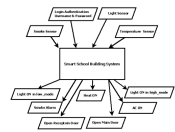 Figure 1: Inputs and Outputs of the Smart School Building System [1]
Figure 2 shows the UML use case diagram of the system. This diagram shows when the actors (student, employee, and visitor) login to the system by entering the username and password correctly, the main door will open, and they will have access to the sub-systems in the building.
Figure 3 [1] shows the UML activity diagram of the smart school building. The activity diagram will help in better understanding how the system works.
Figure 4 provides a UML sequence diagram of the smart school building system. It illustrates the sequence of all actions that happen in the system. As an extension of work in [1] and in order to increase system’s security and eventually safety, the new smart school model requires that each person entering the school has to has a unique username and password. These usernames and passwords will be given by school or school district to each person. Visitors must request a username and password from the school before their visit, i.e., visitors to the school building must have a valid login username and password to be allowed to enter the building.
If the username and password are correct, the main door will automatically be opened. Once the first person enters the building, all systems, including the lighting sub-system and the HVAC sub-system, will automatically start working. The smoke detection system will work all the time, even after school hours, to guarantee safety in the building in case of fire.
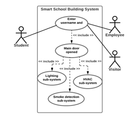 Figure 2: UML Use Case Diagram of the Smart School System
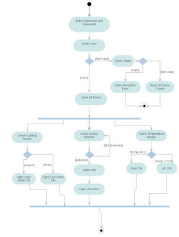 Figure 3: UML Activity Diagram of the Smart School Building System [1]
4. Formal Specification Using TLA+
This section illustrates the formal specification of our extended smart school system model. We use the TLA+ toolbox to write the system’s specifications and the TLC model checker to validate our system. We represent all of the system’s operations using TLA+.
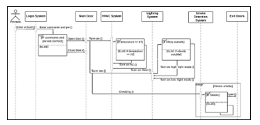 Figure 4: Sequence Diagram for the Smart School Building System
In TLA+, the system’s specifications are called spec, and they are written in a module which we have called in our case smartSchoolSystem. In the module, we include the system’s variables that we will use inside the module as shown in Figure 5.
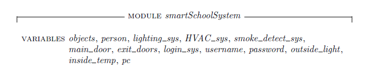 Figure 5: smartSchoolSystem Module Variables
The top module of the smart school system is represented by smartSchoolSystem. The module has the set of variables shown in Figure 5. For example, person variable represents anyone who is allowed to enter the building (employee, visitor, or student). The main_door variable represents the main door for people to enter the school building, and exit_doors represents the doors which will be opened in case of fire/smoke. The username and password variables represent the values of the person’s username and password, and these values must be unique for each individual person.
In any TLA+ module, declaring the Init function, invariants, and Next function is a must. The Init function represents the initial values of the system’s variables, the invariants represent the limitations and conditions in the system, and the Next function represents the next-state action.
In the smartSchoolSystem module, we declared the Init function with the range of all possible values of each variable in the module as shown in Figure 6. For example, main_door variable may take on either open or closed values only. Similarly, person variable may take either student, employee, or visitor values in this spec. The pc variable represents the current state, and pc’ represents the next state as we will see later in the spec.
To ensure that the school building in our system is always safe in case of fire, we designed our system to have a smoke detection sub-system working all the time in and out of school hours. To apply this safety functionality in our system, we added a system invariant and called it safe as shown in Figure 7. This invariant guarantees that the smoke detection system will be working all the time.
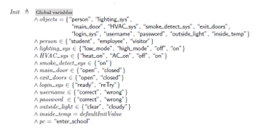 Figure 6: Init Function
![]() Figure 7: System Invariant
Figure 7: System Invariant
The function enter_school is the function that represents any of the employees, students, and visitors entering the school. This function requires the person desiring entry to enter a valid username and password as input in order to open the main door for entrance as an output. If the username and/or the password is wrong, the main door will not open, and the system will ask the person to retry to enter valid values. Figure 8 shows the enter_school function.
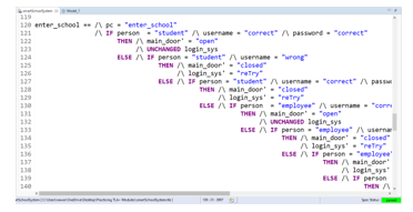 Figure 8: enter_school Function
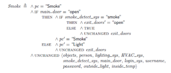 Figure 9: Smoke Function
We set smoke_detect_sys to be on all the time as an invariant in our system as mentioned before. If there is smoke detected from the smoke detection sub-system, in this case smoke function will be on and all exit doors will open automatically to allow all people inside the school to leave immediately for their safety. OF course, the smoke detection sub-system will have a built-in alarm in case smoke is detected. Figure 9 shows the Smoke function.
Once the first person enters the school, the lighting and HVAC sub-systems will automatically start working. In the light function, the light sensor will start sensing the natural outside_light brightness to control the light inside the building. The outside_light could have two values, clear or cloudy. If it is clear outside, the lights inside the building will be turned on by the system in a low_mode. If it is cloudy outside, the lights inside the building will be turned on by the system in a high_mode. This lighting sub-system will help in managing and controlling power consumption in the system. Figure 10 shows the Light function. In practice there will be multiple light sensors for multiple sides of the building.
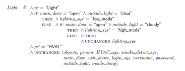 Figure 10: Light Function
The HVAC sub-system helps in controlling the temperature inside the school building. In the HVAC function, the temperature inside the building has been sensed by the temperature sensor and the HVAC sub-system acts based on that. If the inside_temp is more than 74 F, the HVAC sub-system will turn on the AC in the building. If the inside_temp is less than 69 F, the HVAC sub-system will turn on the Heat in the building. If the inside_temp is more than 69 F and less than 74 F, the HVAC sub-system will be turned off. Figure 11 shows the HVAC function.
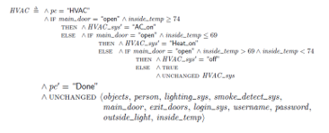 Figure 11: HVAC Function
Figure 12 includes housekeeping functions which are essential for writing good specifications for a system. Some of these functions must be in any TLA+ spec, e.g., the Next function. The Next function enables collection and execution of all functions in the spec and moving to the next state in the system after initialization. The Termination function guarantees the termination when pc reaches Done state. In TLA+, the Spec function is the main function that is responsible to run all system specifications in the main execution of the system.
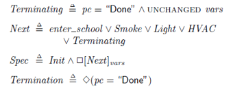 Figure 12: Terminating, Next, and Spec functions
In order to verify that the module is correct and there are no syntax errors in our system, we have used the TLA+ toolbox to write these specifications and save the module. Figure 13 shows the parsed model. As shown in the figure, the green box on the bottom right corner of the screen proves that this model is correctly parsed via the TLA+ toolbox. The next section will describe the system that will be verified through the TLC model checker.
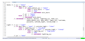 Figure 13: TLA+ Parsed Model for Smart School System
5. Formal Verification Using TLC
In the previous section, we illustrated the smart school system specifications, and we parsed the module correctly using the TLA+ toolbox. We did this in order to verify the model is correct and to validate our work. We used the powerful TLC model checker to debug a TLA+ specification. It checks the specification’s invariance properties of its finite state model [13]. TLC checks for deadlock and the system invariants. In our TLC model, we set the safety invariant to keep the smoke detection sub-system working all the time, as shown in Figure 14. This means that this invariant will guarantee that the smoke detector will work all the time, whether there is someone in the school or not, day and night, to enhance the safety in the school building. As shown in Figure 14 as well, the TLC model checker has a feature to check for a deadlock in the design. It’s an optional feature. In this model, we choose to check for deadlock and it returns that there is no deadlock.
After setting-up the TLC model checker, we ran it to verify our smartSchoolSystem module. Figure 15 shows the TLC model checker while running.
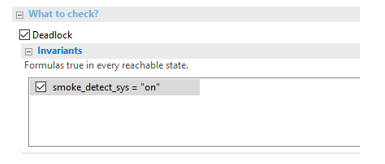 Figure 14: Safety Invariants Setup in TLC
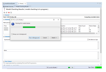 Figure 15: TLC Model Checker While Running
Figure 16 shows the final result for the smartSchoolSystem model. In order to validate a system using the TLC model checker, the model must be parsed, and the model checker should run to completion, and no errors should be detected. Our smart school system was verified and validated correctly using the TLC model checker since, as shown in Figure 16, the TLC model is parsed correctly with no errors, which proves our system’s validation.
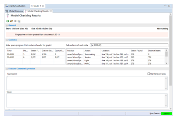 Figure 16: TLC Verification Model
6. Conclusion
This work is an extension of the work in [1]. We have modeled a smart school building system using UML and TLA+. We used UML to define the system’s components and to illustrate the sequence of actions in the system. TLA+ defines the system’s specifications and the system’s behavior. The TLA+ toolbox was used to capture the system’s behavior and to parse the model. The final result was to verify the model using the TLC model checker. The model was successfully verified and validated with the TLC model checker. We used formal methods to validate our design and to make sure there are no errors in the design. In this design a failure may still happen. For example, if we simulated the design and built the school from this model, we could have a failure in the lighting system because in practice we will need a light sensor in each room. But our design assumes that the light will be the same in the whole building. This design is an initial and general design to show and explain our methodology, details such as the more complex lighting system would be needed in the final design.
To enhance security and safety in the system, the system requires each person who enters the building to login by entering a valid username and password. To enhance the safety as well, the smoke detection sub-system is working all the time. To control the power in the system, the lighting sub-system will use natural light when possible to reduce the power consumption in the building.
In future, we will work on improving the system by adding more sub-systems to it to enhance system security and safety.
Conflict of Interest
The authors declare no conflict of interest.
Acknowledgment
Figure 2 and Figure 4 were made using chart-making tools at www.lucidchart.com and the authors would like to thank the website. Figures 5,6,7,9,10,11,12 were taken from the TLA+ tool that uses LaTeX translator to generate pretty-printed specs. Figures 8,13,14,15,16 were taken from the TLA+ toolbox. The authors would like to thank Mr. Leslie Lamport for the TLA+ tool which is essential in this work. The authors would also like to thank the University of Cincinnati for its support.
- N.H. Obeidat, C. Purdy, “Modeling a smart school building system using UML and TLA+,” in Proceedings – 3rd International Conference on Information and Computer Technologies, ICICT 2020, Institute of Electrical and Electronics Engineers Inc.: 131–136, 2020, doi:10.1109/ICICT50521.2020.00028.
- P.S. Aithal, Smart Library Model for Future Generations (June 30, 2016). International Journal of Engineering Research and Modern Education (IJERME),1(1), 693-703. ISSN (Online): 2455 – 4200, (2016)., Available at SSRN: https://ssrn.com/abstract=2822978
- A. Rehman, S. Latif, N.A. Zafar, “Formal modeling of smart office using activity diagram and non deterministic finite automata,” in 2019 International Conference on Information Science and Communication Technology, ICISCT 2019, Institute of Electrical and Electronics Engineers Inc., 2019, doi:10.1109/CISCT.2019.8777444.
- F.K. Santoso, N.C.H. Vun, “Securing IoT for smart home system,” in Proceedings of the International Symposium on Consumer Electronics, ISCE, Institute of Electrical and Electronics Engineers Inc., 2015, doi:10.1109/ISCE.2015.7177843.
- Z. Yu, Y. Liang, B. Xu, Y. Yang, B. Guo, “Towards a smart campus with mobile social networking,” in Proceedings – 2011 IEEE International Conferences on Internet of Things and Cyber, Physical and Social Computing, iThings/CPSCom 2011, 162–169, 2011, doi:10.1109/iThings/CPSCom.2011.55.
- A. Clark, A. Evans, “Foundations of the Unified Modeling Language.,” In Proceedigs of the 2nd Northern Formal Methods Workshop. Springer, 1997.
- L. Pierre, T. Kropf, Correct Hardware Design and Verification Methods: 10th IFIP WG10.5 Advanced, 1999.
- S. Tasiran, Y. Yu, B. Batson, S. Kreider, Using formal specifications to monitor and guide simulation: Verifying the cache coherence engine of the Alpha 21364 microprocessor, 2002.
- C. Newcombe, “Why Amazon chose TLA+,” in Lecture Notes in Computer Science (including subseries Lecture Notes in Artificial Intelligence and Lecture Notes in Bioinformatics), Springer Verlag: 25–39, 2014, doi:10.1007/978-3-662-43652-3_3.
- S. Latif, A. Rehman, N.A. Zafar, “Modeling of sewerage system linking UML, automata and TLA+,” in 2018 International Conference on Computing, Electronic and Electrical Engineering, ICE Cube 2018, Institute of Electrical and Electronics Engineers Inc., 2019, doi:10.1109/ICECUBE.2018.8610971.
- S. Latif, A. Rehman, N.A. Zafar, “NFA based formal modeling of smart parking system using TLA +,” in 2019 International Conference on Information Science and Communication Technology, ICISCT 2019, Institute of Electrical and Electronics Engineers Inc., 2019, doi:10.1109/CISCT.2019.8777445.
- J.R. Abrial, “Formal methods in industry,” in Proceeding of the 28th international conference on Software engineering – ICSE ’06, Association for Computing Machinery (ACM), New York, New York, USA: 761, 2006, doi:10.1145/1134285.1134406.
- L. Lamport, Specifying Systems Preliminary Draft, 2001.
- R. Adner, D. Levinthal, “Demand heterogeneity and technology evolution: Implications for product and process innovation,” Management Science, 47(5), 611–628, 2001, doi:10.1287/mnsc.47.5.611.10482.
- K. Furdik, G. Lukac, T. Sabol, P. Kostelnik, “The Network Architecture Designed for an Adaptable IoT-based Smart Office Solution,” International Journal of Computer Networks and Communications Security, 1(6), 216–224, 2013.
- Y. Geng, C.G. Cassandras, “New ‘smart parking’ system based on resource allocation and reservations,” IEEE Transactions on Intelligent Transportation Systems, 14(3), 1129–1139, 2013, doi:10.1109/TITS.2013.2252428.
- A. Zanella, N. Bui, A. Castellani, L. Vangelista, M. Zorzi, “Internet of things for smart cities,” IEEE Internet of Things Journal, 1(1), 22–32, 2014, doi:10.1109/JIOT.2014.2306328.
- B. Hirsch, J. WP. Ng., “Education beyond the cloud: Anytime-anywhere learning in a smart campus environment.” IEEE International Conference for Internet Technology and Secured Transactions. , 2011.
- Smart Campus: The Developing Trends of Digital Campus–Open Education Research 2012-04 , Mar. 2021
- M.R.M. Veeramanickam, M. Mohanapriya, “IOT enabled Futurus Smart Campus with effective E-Learning: i-Campus,” GSTF Journal of Engineering Technology (JET), 3(4), 2016, doi:10.5176/2251-3701_3.4.164.
- L. Pocero, D. Amaxilatis, G. Mylonas, I. Chatzigiannakis, “Open source IoT meter devices for smart and energy-efficient school buildings,” HardwareX, 1, 54–67, 2017, doi:10.1016/j.ohx.2017.02.002.
- D. Amaxilatis, I. Chatzigiannakis, G. Mylonas, Design and Implementation of a Platform for Smart Connected School Buildings, 2015.
- Y. Qu, H. Wang, S.M. Lun, H.D. Chiang, T. Wang, “Design and implementation of a Web-based Energy Management Application for smart buildings,” in 2013 IEEE Electrical Power and Energy Conference, EPEC 2013, IEEE Computer Society, 2013, doi:10.1109/EPEC.2013.6802931.
- M. Brogan, A. Galata, The VERYSchool Project: Valuable EneRgY for a smart School-Intelligent ISO 50001 Energy Management Decision Making in School Buildings.
- P.G. Larsen, W. Pawlowski, “The formal semantics of ISO VDM-SL,” Computer Standards and Interfaces, 17(5–6), 585–601, 1995, doi:10.1016/0920-5489(95)00026-Q.
- The Object-Z Specification Language – Graeme Smith – Google Books, Mar. 2021.
- D. Jackson, “Alloy: A Lightweight Object Modelling Notation,” ACM Transactions on Software Engineering and Methodology, 11(2), 256–290, 2002, doi:10.1145/505145.505149.
- T. De Champs, B. Abdulrazak, H. Pigot, M. Ouenzar, M. Frappier, B. Fraikin, “Pervasive safety application with model checking in smart houses: The INOVUS intelligent oven,” in 2011 IEEE International Conference on Pervasive Computing and Communications Workshops, PERCOM Workshops 2011, 630–635, 2011, doi:10.1109/PERCOMW.2011.5766965.