
Usage of Additive Manufacturing and Topology Optimization Process for Weight Reduction Studies in the Aviation Industry
Volume 6, Issue 2, Page No 815-820, 2021
Author’s Name: Tamer Saraçyakupoğlua)
View Affiliations
Department of Aeronautical Engineering, Istanbul Gelisim University, Istanbul, 34315, Turkey
a)Author to whom correspondence should be addressed. E-mail: dr.tamer@tamersaracyakupoglu.com.tr
Adv. Sci. Technol. Eng. Syst. J. 6(2), 815-820 (2021); ![]() DOI: 10.25046/aj060294
DOI: 10.25046/aj060294
Keywords: Aircraft, Additive Manufacturing, Engine Mount, Topology Optimization, Weight Reduction

Export Citations
The Additive Manufacturing (AM) technology is a disruptive and novel technique that changes the paradigm of manufacturing methodology. It is based on the principle of having 3D parts by adding simple 2D layers on and on. Before AM was implemented, the conventional subtractive and chip-away techniques such as milling and turning processes had been used widely in the aviation industry. The mentioned conventional methods are still in use. However, it is observed that AM replacing legacy methods, especially for the complex and relatively heavy parts. Thanks to mutual-usage of the Topology Optimization (TO) techniques and AM, many weight reduction studies have been done successfully. The weight reduction studies have an impact on the Direct Operational Cost (DOC) of the aircraft. With the benefit of weight reduction studies, many airliner companies have the opportunity for carrying more payloads with the same type of commercial-passenger aircraft. Also, the TO and weight reduction studies are beneficial for lowering the carbon footprint. Obviously, the weight reduction, the DOC, and the carbon emission are interrelated with each other. In this paper, a research was carried out for a generic engine mount that is specifically used by famous aircraft types. Eventually, it was found that, with the help of AM, TO and material optimization studies it is possible to save weight on the engine mount.
Received: 25 December 2020, Accepted: 24 March 2021, Published Online: 31 March 2021
1. Introduction
The aviation industry is a pioneer of the integration of novel manufacturing technologies because it requires high technologies. International Civil Aviation Organization (ICAO), stated in its 2016–2030 Capacity and Efficiency Report that, since 1977 the global air passenger volume has been expanding two-fold once every 15 years and will continue to do so [1]. The International Air Transport Association (IATA) is an important association, declared that almost 8,2 billion people will be flying in 2037 [2]. These two reports from two strong organizations are complementing to each other. The reason for this increasing trend in aviation traffic is because of the more frequent mobilization demand.
On the other hand, the aircraft companies are seeking the implementation of novel technologies such as AM into the aviation industry in terms of having lighter airplanes. Because lighter aircraft means having more passengers, bigger payloads, reaching longer ranges, higher maneuver capacities, more comfortable services, and easier maintenance abilities, etc.
Like all other novel technologies that are implemented in the aviation industry, the AM has vital importance because it is a pillar of industry 4.0 [3]. For example, the aviation industry was the earliest adopter of carbon fiber materials, and it was the first to integrate CAD/CAM into its design process [4]. The use of AM technologies has become increasingly widespread for three decades, starting with rapid prototyping studies [5]. The implementation of AM has been the fastest one, particularly in the aviation industry because of its unbeatable advantages. While reducing the weight of a part, maintaining the same mechanical features as its traditionally produced predecessors is vital.
There are some constraints in the aviation industry. The implementer always has to follow the airworthiness regulations. As an airworthiness authority, the ICAO took attention to the implementation of the new technologies that may have a negative impact the aviation safety [6]. There are many successful samples for additively manufactured airborne parts. For example, General Electric’s (GE) fuel nozzle is an iconic part that has been manufactured with AM technologies. For the Leading Edge Aviation Propulsion (LEAP) engines. GE has combined 20 parts into 1 part, produced in a single machine, and decreased the weight up to 25% less than the conventionally manufactured predecessors [7]. Federal Aviation Administration (FAA) announced that more than 40.000 nozzles will be manufactured by the end of 2020 [8]. The mentioned nozzle also contributes to clean fuel burn and helps to reduce the carbon deposits [9].
In the open literature, there are studies regarding manufacturing the engine mount by Additive Manufacturing methods. In [10], made an investigation for the engine mount of a truck that works under low and high cyclic loads similar to an aircraft engine mount. In this study, it was found that producing the engine mount using Additive Manufacturing is possible. In another study [11], the author investigated the usage of topology optimization and additive manufacturing for weight optimization of an engine subframe mount used. In this study, it was underlined that 20% of weight reduction is possible of the mentioned mount.
In the mentioned papers, the studies were mainly focused on the automotive related parts. However, in this study, a general aviation engine mount was examined.
2. The Relation Between the Weight of the Aircraft and the Impact of Forces
For weight reduction studies, sorts of weight should be clarified. The impacts of the main four forces affect the design of an airplane.
2.1. Four Main Forces
As it is depicted in Figure 1, four major forces shape the flight. Roughly these forces are categorized as,
- Thrust: The force which is generated by the engines and moves the aircraft in the air.
- Drag: The aerodynamic force is generated by the surface of the aircraft and opposes an aircraft’s move through the air. It is a result of air-friction.
- Lift: The force which has an upward direction and it is mainly generated by the wings. The lift enables the aircraft to stay airborne.
- Weight: Weight is the force that is generated by the gravity on the aircraft. It is depended on the mass of the body.
In a level and straight flight, an aircraft is in equilibrium since these four forces are well balanced and their moments are zero. The lift should balance the weight and the thrust should balance the drag. In conclusion, the four forces must be in equilibrium during flight [12]. The rate of climb is an indicator of the stability of the airplane. Increasing weight is an undesirable situation [13]. The equilibriums that are basically given in (2-1) and (2-2) are the vertical and horizontal loads of an aircraft.
Thrust – Drag – (Weight X Sinα) = 0 (1)
Lift – (Weight X Cosα) = 0 (2)
As it is demonstrated in Figure 2, the rate of climb is directly related to the weight of the airplane.
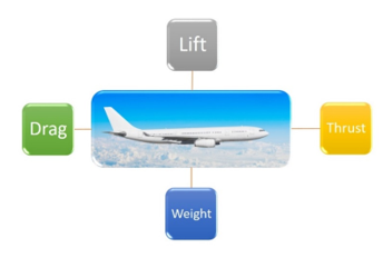 Figure 1: The Four Main Forces that Affect the Flight [12]
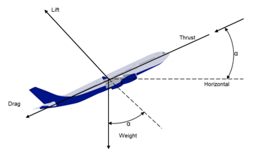 Figure 2: Rate of Climb [14]
As it can be seen for having a better climb performance, the increased thrust, the lowered drag, and the weight are crucial. Through the next paragraph, sorts of weight will be described shortly.
2.2. The General Weight sand Loads
There are many weight types regarding the aircraft’s configuration. In pursuit of weight reduction, some important weight definitions are given below;
- Maximum Zero Fuel Weight (WMZF) is the maximum weight that an aircraft can carry with no fuel.
- Design Gross Weight (W0) is the weight of the aircraft as it initiates the mission for the design purpose.
- Empty Weight (We, Wempty) is the weight of an airplane without useful fluids like oil, hydraulic fluids, and trapped (unusable) fuel. It should be emphasized that We include airframe, landing gears, structural parts, empennage, engines, avionics, and all other equipment.
- Crew Weight (Wc, Wcrew) is the weight of the cockpit crew that is required for flying the aircraft.
- Fuel Weight (Wf, Wfuel) is the weight of the fuel which is necessary for the accomplishment of the design mission.
- Weight of Payload (Wp, Wpayload) is the parameter of cargo and/or passenger.
- Weight of Useful Load (Wu) is the weight of all other things the aircraft has the capability of carrying besides her own weight [14].
The difference between Wu and Wp has crucial importance for an airliner since the lesser fuel means more freight and more passengers.
2.3. Weight Relations
There’s a correlation amongst the sort of weights. The primary equations and ratios are provided as follows:
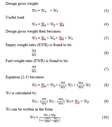 Different types of aircraft demonstrate varying characteristics depending on the Empty Weight Ratio [15]. Conclusionally, AM techniques are used for reducing the W0.
2.4. Categorization of AM and the Materials
American Society for Testing and Materials (ASTM) released a standard for categorizing the AM techniques which are called “Standard Terminology for Additive Manufacturing Technologies, Designation: F2792 − 12a” [16]. This standard mainly classifies AM techniques into seven categories. These are:
- Binder jetting,
- Directed energy deposition,
- Material extrusion,
- Material jetting,
- Powder bed fusion,
- Sheet lamination,
- Vat photopolymerization.
The material selection is based on the customer requirements and there are some hybrid methods as well. In every AM process, the processing material differs from one to another. For example, wax-like materials can be processed with material jetting and binder jetting. Metals such as nickel-based alloys and aluminum can be processed with directed energy deposition. Thermoplastic filaments can be processed with Material Extrusion. With powder bed fusion the materials such as nickel-based superalloys, Inconel 625, Inconel 718, polymers, maraging steel, stainless steel 316 L, 15-5PH, 17-4PH, Hastelloy X, titanium TA6V, and chrome-cobalt can be processed. Adhesive coated papers, metal tapes, and foils, the plastic sheet material can be processed with sheet lamination, and light-curable resin and photopolymers can be processed with Vat Photopolymerization.
2.5. W0 Reduction and Topology Optimization Relationship
An aircraft is not permitted to fly unless it is made of airworthy parts airworthy part certification is given and validated by airworthiness authorities only. Because of the design freedom available with AM techniques, topology optimization (TO) of the airworthy parts which are used on the airplanes are perfect applications [17]. For example, GE’s engine nozzle that was mentioned in the introduction paragraph is lighter 25% after AM application. In another study, thanks to AM and TO studies, European Aeronautic Defense and Space Company (EADS) redesigned the nacelle hinge brackets of Airbus A320 as depicted in Figure 3. The brackets’ weight saved up to 64% while keeping the mechanical features satisfactory [18].
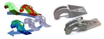 Figure 3: TO and AM Application of Airbus A320 Nacelle Hinge Bracket [18]
The result of TO studies always benefited the buy-to-fly-ratio. Buy-to-fly-ratio is formulated as follow;
![]() With AM technologies, the buy-to-fly ratio can be minimized to 1:1 [19]. It is a very critical benefit since aviation materials are expensive in the market as mentioned before. Besides buy-to-fly-ratio, with the usage of AM technologies there are some other benefits such as given below;
With AM technologies, the buy-to-fly ratio can be minimized to 1:1 [19]. It is a very critical benefit since aviation materials are expensive in the market as mentioned before. Besides buy-to-fly-ratio, with the usage of AM technologies there are some other benefits such as given below;
- The cost of the parts may be reduced to almost half,
- Part weight can be reduced to 64%
- Scrap reduction can be as low as 10%,
- Time-to-market can be reduced to 64% [20].
As it was mentioned previously, weight reduction studies generally conclude with the lower fuel consumption and increased load capacity of aircraft [21]. For example, the Boeing company stated that Boeing 777-300 has improved its fuel economy against Boeing 767-300 and succeed to take up to 368 passengers compared to 269 passengers in Boeing 767-300ER thanks to the weight reduction studies [22]. In another study, from the Airbus project called the SAVING, by redesigning the seat buckles of Airbus 380, 55% of weight has been saved over seat buckles. With the help of the TO and AM studies, in a regular configuration, for the Airbus 380 which has 853 seats the saving would be a total of 72,5 kg of weight [23]. With project SAVING, a total of 3,3 million liters of fuel savings is targeted to gain over the service life of the aircraft Airbus A380 [24]. In addition to the commercial aviation industry on the military side, there are some studies such as Lockheed Martin’s Joint Strike Fighter (JSF)’s engine Bleed Air Leak Detector (BALD) bracket. For the mentioned bracket the buy-to-fly ratio is reduced to 1:1, as compared with the 33:1 ratio possible by conventional methods with the advantage of 50% in total cost [25]. In accordance with the cost studies, the fuel and oil consumption in airliner operational cost is the top driver with a percentage of 33,4%. The Aircraft Ownership as the second item with 10,6 percentage is far below Fuel & Oil [26]. It is known that for an airliner company that owes more than 600 aircraft, such as American Airlines, reducing even one pound of weight from each aircraft saves approximately 11,000 gallons of fuel annually. On the other hand, a lesser carbon footprint can be gained by the reduction of the W0 of the airplanes. For example, For the Boeing 747-400, which has 396,890 kg of W0, and Airbus A330-300, which has 242,000 kg of W0 with the weight reduction of one kg built-in aircraft it, is possible to reduce carbon emissions up to 0.94 kg and 0.475 kg respectively [27].
3. Materials and Method
In general, before presenting further information regarding W0 and TO correlation the relation between design and TO should be provided.
3.1. Design and Topology Optimization Relation
For W0 and TO studies the mechanism of the design process should be described. As it is presented in Figure 4, design can be described as a feature of an object, which is initiated by an agent, for handling the goals, in a framed environment, using a set of fundamental components to satisfy a set of requirements in a designated environment [28].
The conceptual design method provided in Figure 4. covers the general approaches in terms of designing. This concept can be adapted to legacy and novel technologies such as Additive Manufacturing. The relation between design and manufacturing is a crucial indicator of the success of fields such as material development, thermodynamics, aerodynamics, structural integration, heat transfer, and machining as well [29]. While using AM techniques, the core of the whole process is creating a CAD model. In other words, a CAD model initiates the AM process [30]. In Figure 5, the CAD model and the following steps of the AM process are shown in consecutive steps.
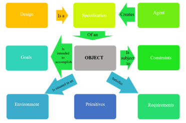 Figure 4: Conceptual Model of Design [28]
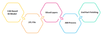 Figure 5: The steps of AM [22]
3.2. Steps of Topology Optimization
As it is shown in Figure 6, the preparation of data is the first step and includes important issues such as material definition and CAD model preparation. The second step is topology optimization which includes the steps of creating a finite element model and finite element analysis. The third step is the TO result from adaptation. And finally, the fourth step is creating a final finite element model and CAM model.
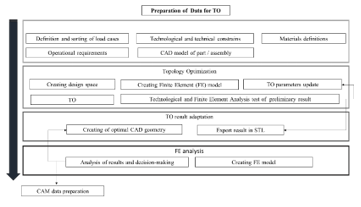 Figure 6. The Steps of Topology Optimization [31]
4. Results and Discussion
There are many investigations and research studies on the application of TO in the aviation industry [32;33;34]. In this study an engine mount which is shown in Figure 7. is selected. It is a generic engine mount that is used for the Ultra-Light (U/L) airplanes in the market which have retractable landing gears and 250 km/h of cruise speed. The basic equations are given in section 2.3. are valid for the U/L aircraft types. These U/L aircrafts are famously known as low-speed general aircrafts [35] with the Design Gross Weight up to 472,5 kg.
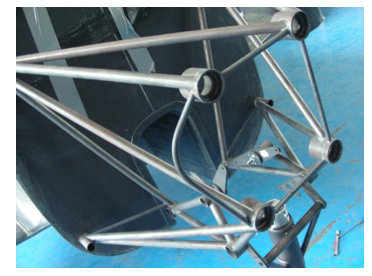 Figure 7. A Common Engine Mount for the U/L Airplanes(Image Courtesy of the Correspondent Author)
The engine mount is a vital part that is attached to the airframe of the airplane. It holds the engine while dampening the effect of vibrations and transmitting forces between the engine and the airplane body structure. As it is shown in Figure 8. the engine mount is installed in front of the firewall in the engine bay. It is located between the firewall and the engine. Generally, 4130 steel is preferred for producing engine mounts because of reliable heat-treating practices and processing techniques [14]. The weight of the engine mount is 10,4 kg as its twin which is used in black-shape aircraft [36].
As it is shown in Figure 8-a, a CAD model of the mentioned engine mount is shown while the STL model is provided in Figure 8-b.
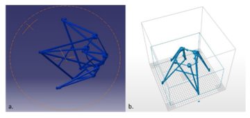 Figure 8: (a) The 3D Solid-form of Engine Mount, (b) The STL-form of Engine Mount (Generated by authors using Catia V5 R21 )
During the AM process, Carbon Fiber Reinforced Polymer (CFRP) is selected in terms of reducing the weight and while maintaining the same or exceeds mechanical properties. The weight of the engine mount which is manufactured by using CFRP is about 2 kg. In Table 1, the density comparison between before and after materials is provided.
Table 1. The Density Comparison Between Engine Mount Materials [37]
| S.No | Material Type | Density (gr/cm3) |
| 1 | 4130 Steel | 7,8 |
| 2 | Aluminum 7075 | 2,7 |
| 3 | Carbon Fiber Reinforced Polymer (CFRP) | 1,6 |
With this study, it is shown that almost 8 kg of saving can be achieved by using AM technology instead of legacy methods. The 8 kg of weight saving is a significant amount when it is compared with the Gross Design Weight of general aviation U/L category air vehicles.
5. Conclusion
This study presents the importance of W0 reduction studies in the aviation industry. It highlights the previous W0 reduction studies while submitting information about AM and TO studies. In many cases, it is observed that the weight of the original part reduces after AM and TO application. An engine mount was provided as a sample of the TO model. Based on the experimental study the followings are noteworthy conclusions;
- Based on the experimental study it can be claimed that with the usage of AM technologies, the weight of the generic engine mount can be reduced with the same or exceeded mechanical features and functionality.
- The vertical and horizontal vector stability is a crucial issue for aircraft mass and balance. In this manner, any study for weight reduction should be subjected to further investigations in terms of mass and balance studies.
- Decreasing the weight of the engine mount has a direct effect on the fuel-saving in short term, however has a beneficial effect on less carbon emission in long term.
- With the topology optimization studies based on the investigation of the researched engine mount, the weight reduction studies can be done and implement in general aviation projects.
- It is recommended to make further studies with Ti6AL4V alloy that has a wide potential in the aviation industry.
Weight reduction studies in the aviation industry will gain more importance in the future. Conclusionally, the TO and AM studies will have gain more importance as they are beneficial for both decreasing the operational cost and carbon emissions.
Conflict of Interest
The authors declare no conflict of interest.
Acknowledgment
The author’s AM studies such as weight reduction etudes and a patent are encouraged by Artuk Aviation Ltd. Company which is located in Afyonkarahisar/Turkey. The author is immensely grateful to Artuk Aviation Ltd. for supporting his engineering studies.
- ICAO, Capacity and Efficiency Report, 2016–2030 Global Air Navigation Plan, 6, 2016, ISBN: 978-92-9258-000-1.
- M. Bagamanova “A multi-objective optimization with a delay-aware component for airport stand allocation”, Journal of Air Transport Management, 83(1), 212-220, 2020, https://doi.org/10.1016/j.jairtraman.2019.101757.
- I. Guyon, “Analysis of the opportunities of industry 4.0 in the aeronautical sector”, 10th International Multi-Conference on Complexity, Informatics and Cybernetics: IMCIC 2019 Orlando, United States: HAL archives & ouvertes fr., 3, 2019, https://hal.archives-ouvertes.fr/hal-02063948
- Stratasys, “Additive Manufacturing Trends In Aerospace”, 1, 2014.
- A.E. Jakus, “An Introduction to 3D Printing Past, Present, and Future Promise.”, F. M. Matthew Dipaola inside, 3D Printing in Orthopaedic Surgery, 10, 2019, https://doi.org/10.1016/B978-0-323-58118-9.00001-4
- ICAO,”Strengthening Regional Safety Oversight”, 11, 2018 Doc. No.: AN-Conf/13-WP/158
- E. Yasa “Additive Manufacturing of Polymer Matrix Composites”, in, Kushan M. C., “Aircraft Technology”, 148, 119-125, 2018, https://doi.org/10.5772/intechopen.75628
- FAA, “Regulatory Considerations for AM Qualification and Status of FAA AM Roadmap”, “Additive Manufacturing for Reactor Materials & Components Public Meeting”, 8, 15-21, 2017.
- FAA , “TAPS II Combustor Final Report”, 25, 2018.
- Böckin, D., Tillman, A.M., “Environmental assessment of additive manufacturing in the automotive industry”, Journal of Cleaner Production, 226, 977-987, 2019, https://doi.org/10.1016/j.jclepro.2019.04.086.
- A. Merulla et al., “Weight reduction by topology optimization of an engine subframe mount, designed for additive manufacturing production”, Materials Today: Proceedings, 19(3), 2019, https://doi.org/10.1016/j.matpr.2019.08.015
- P.J. Swatton, “Principles of Flight for Pilots”, Wiley Aerospace Series, 81, 2010, ISBN: 978-0-470-71073-9
- J.D. Anderson, “Aircraft Performance and Design”, USA: Tata McGraw and Hill, 125, 2010, ISBN-13: 978-0-07-070245-5
- S. Gudmundsson, “General Aviation Aircraft Design: Applied Methods and Procedures”, Butterworth-Heinemann of Elsevier, 145, 2014, http://dx.doi.org/10.1016/B978-0-12-397308-5.00001-5.
- D.P. Raymer, “Aircraft Design: A Conceptual Approach”, American Institute of Aeronautics and Astronautics, 14, 1992, ISBN 0-930403-51-7
- ASTM,”Standard Terminology for Additive Manufacturing Technologies. Designation: F2792 – 12a”, 1-2, 2013.
- M. Tomlin, “Topology Optimization of an Additive Layer Manufactured (ALM) Aerospace Part”, 7th Altair CAE Technology Conference, 1, 2011.
- J. Zhu et al., “Topology Optimization in Engineering Structure Design”, ISTE Press Ltd and Elsevier Ltd., 22, 2016, http://dx.doi.org/10.1007/s11831-015-9151-2
- A. Barz, “A Study on the Effects of Additive Manufacturing on the Structure of Supply Networks”, Archives of Computational Methods in Engineering, 23 (4), 2016, 10.1016/j.ifacol.2016.03.013
- Deloitte University, “3D opportunity in aerospace and defense: Additive manufacturing takes flight”, 4, 2014.
- L. Nickels, “AM and aerospace: an ideal combination”, Metal Powder Report, 70 (1), 2015, https://doi.org/10.1016/j.mprp.2015.06.005
- M.R. Mansor et al., “Natural fiber polymer composites: Utilization in Aerospace Engineering. E. F. Deepak Verma” in, Biomass, Biopolymer-Based Materials, and Bioenergy, Woodhead Publishing, Elsevier, 212, 2019, https://doi.org/10.1016/B978-0-08-102426-3.00011-4
- B. Badiru A., V. Valencia V., Liu D., “Additive Manufacturing Handbook”, Taylor and Francis Group., 271, 201), ISBN: 13: 978-1-4822-6408-1
- S. Singamneni et al., “Additive Manufacturing for the Aircraft Industry: A Review”, Journal of Aeronautics & Aerospace Engineering, 8, 2019, https://doi.org/10.4172/2329-6542.1000214
- R. Dehoff et al., “Additive Manufacturing of Aerospace Brackets” Advanced Materials and Processes, 5, 2013.
- L. Gorbatikh, “Hierarchical lightweight composite materials for structural applications”, MRS Bulletin, 41(9), 672-677, (2016). doi:https://doi.org/10.1557/mrs.2016.170
- IATA, “Airline Cost Structure”, “Airline Cost Management Group (ACMG), 11, (2015)
- P. Ralph “A Proposal for a Formal Definition of the Design Concept” in Lyytinen K., Loucopoulos P., Mylopoulos J., Robinson B., “Design Requirements Engineering: A Ten-Year Perspective”. Kalle Lyytinen inside, Design Requirements Engineering: A Ten-Year Perspective, 108, 2009, https://doi.org/10.1007/978-3-540-92966-6_6
- P. Han, “Additive Design and Manufacturing of Jet Engine Parts”, Journal of Engineering, 1, 2017, https://doi.org/10.1016/J.ENG.2017.05.017
- F. Liou, “Rapid Prototyping and Engineering Applications: A Toolbox For Prototype Development”. CRC Press, 125, 2019, ISBN: 13: 978-1-4987-9892-1
- K.V. Fetisov, “Topology optimization and laser additive manufacturing in design process of efficiency lightweight aerospace parts”, Journal of Physics, 4, 2018, https://doi.org/10.1088/1742-6596/1015/5/052006
- K.S. Reddy et al.,” Topology Optimization Software for Additive Manufacturing: A Review of Current Capabilities and a Real-World Example ” in Proceedings of the ASME 2016 International Design Engineering Technical Conferences and Computers and Information in Engineering Conference, 4-5, 2016.
- M. Seabra et al., “Selective laser melting (SLM) and topology optimization for lighter aerospace components”,in XV. Portuguese Conference on Fracture, 5-6, 2016.
- C. Emmelmann “Laser Additive Manufacturing and Bionics: Redefining Lightweight Design”, Physics Procedia, 4, 2011, doi:10.1016/j.phpro.2011.03.046
- W. Dawei et al., “Safety and Airworthiness Design of Ultra-Light and Very Light Amphibious Aircrafts”, Procedia Engineering, 17, 212-225, 2011, https://doi.org/10.1016/j.proeng.2011.10.023
- B. Lierop, “Handling qualities criteria for training effectiveness assessment of the BS115 aircraft”, Delft University of Technology, 77, 55-68, 2017.
- L. Gorbatikh et al., “Hierarchical lightweight composite materials for structural applications”, MRS Bulletin, 41(9), 672-677, 2016. doi:https://doi.org/10.1557/mrs.2016.170