Discretisation of Second Order Generalized Integrator to Design the Control Algorithm of Unified Power Quality Conditioner

Adv. Sci. Technol. Eng. Syst. J. 6(2), 808–814 (2021);
 DOI: 10.25046/aj060293
In this paper, second order generalized integrator (SOGI) is discretized to design the control algorithm of unified power quality conditioner (UPQC). A UPQC is combination two voltage source converter (VSC) and VSC are connected with back to back DC link. The first one VSC is in series to maintain the desire voltage at point of common coupling (PCC) and second is connected with shunt VSC to share the reactive power demand of load. Moreover, it protects the AC mains from pollution of the load. A phase lock loop (PLL) based SOGI model is implemented to design an algorithm for UPQC under light polluted load. Whereas under highly polluted load the Laplace Transformation based PLL-SOGI model is fail to eliminate harmonics of current and voltage at PCC. Thus, a discretization of PLL-SOGI is needed to meet disadvantage. In this paper, reference current is generated under polluted load using discretization of PLL-SOGI model and compared it with actual current to pulse the gate of shunt VSC. Moreover, a feedback unit (m) is proposed to pulse the gate of series VSC under voltage sag/swell condition. A hardware setup is performed in the lab to verify the proposed algorithm under highly polluted load.
1. Introduction
This paper is extension of original work, existing in 2020 IEEE 9th Power India International Conference (PIICON) [1]. In this paper, recent demand of electrical energy consumers and services are satisfied with international standard like Institute of Electrical and Electronics Engineers (IEEE) and International Electrotechnical Commission (IEC). It is done by using custom power devices (CPDs). The various kinds of CPDs are available in the present market while authors have chosen Unified Power Quality Conditioner (UPQC). This is unified controller to suppress the burden like current harmonics at source side and voltage harmonics at point of common coupling (PCC) of electrical distribution system [2]. Moreover, it suppresses the voltage related problems like voltage sag and swell at PCC [3]. A UPQC consist two voltage source converters (VSCs), associated back to back DC link. One VSC is connected in series w hereas second one is coupled in parallel to the load [4, 5]. The VSC is nothing without control algorithms which generates pulse . Thus, shunt and series part of VSCs require good control algorithms to improve the multiple power quality of the 3-phase AC primary distribution system [6-8]. The second order generalized integrator (SOGI) is the simple control approach which gives the information like time, magnitude and phase angle of the signals [9]. The SOGI have phase lock loop (PLL) combination and frequency locked loop (FLL) combination [10, 11]. The PLL based configuration of SOGI is discretization in the proposed work. The literature survey indicates many resemble works are reported in grid synchronization using SOGI [12, 13] to extract harmonics. In [14], SOGI based control approach to reduces sensors whereas power quality enhancement is reported in [15, 16]. A SOGI-PLL is presented in [17] to extract active and reactive power. A PLL based second and third order mixed generalized integrated is implemented in grid connected inverter [18]. As the order of equation is increased the further calculation require which again burden for programming to design a controller. Generally, PLL-SOGI and other modified SOGI are applicable to synchronize the voltages/currents signals [19, 20]. The phase of two periodic waves are minimized by PLL. Thus, two phases are synchronized exactly in the proposed algorithms whereas back to back DC level voltage is increased to proper synchronization of two phases. The proposed configuration of SOGI is able to create two output signals. These output signals provide active and reactive components in the direct axis (α-axis) and quadrature axis (β-axis) respectively. Under polluted loads the point of common coupling (PCC) and AC mains get effected which produces harmonics. Thus, input currents/voltages signals of PLL-SOGI contains harmonics while output active components is passed through bandpass filter which reduces the harmonics components of current (iα) and voltage (vα) at certain level. Moreover, reactive component is passed through low pass filter at 900 degree of input signal. It gives reactive component (β) of current (iβ) and voltage (vβ). These voltages and currents signals are helpful to calculate real time active power (pL(t)) and reactive power qL(t). While, researchers have found many ways to calculate real time pL(t) and qL(t) power [21-23]. Moreover, way of extraction of instantaneous power search accuracy of active and reactive component. Thus, in this work, PLL-SOGI is discretized using trapezoidal method. The trapezoidal methods measures accurate 900 degree lagging with respect to input signal under heavy polluted loads [24]. It helps to measure accurate instantaneous power of pL(t) and qL(t). The authors have following contributions in the present work which are given as follows,
- PLL-SOGI is discretized to design the control algorithm of UPQC which pulses the shunt part of VSC and series part of the VSC
- The reference signals of the AC mains currents are generated using simple mathematical calculation.
- A feedback unit ‘m’ is proposed to mitigate the voltage sag and swell at PCC.
Furthermore, in section 2, a brief information of model configuration is presented whereas section 3, control algorithm of UPQC is given. Results and discussion are shown in section 4 and in the last section 5 conclusion is presented.
2. Model Configuration
In Figure 1, a model arrangement of 3-phase, AC mains is connected with UPQC to mitigate the voltage sag, swell, reactive power and eliminate harmonics. The series part VSC of the UPQC is connected left from the PCC whereas shunt part VSC of UPQC connected at PCC. The back to back DC link voltage is maintained 180V for proper and fast working of the proposed algorithms. The DC link capacitor value is estimated nearly 3.3 mF. The AC mains supplies line voltage 110V at 50Hz to polluted load current with 20% THD and its apparent power is 819VA. The switching harmonics of series and shunt VSC are eliminated by R-C filters. The value of R and C are 10Ω and 10μF respectively. The series VSC is interfaced by series transformer whereas shunt VSC is interfaced by inductors value 8 mH. The control algorithm of series and shunt part are separately developed. In the control algorithm block, authors have contributed to develop an idea of algorithm for series VSC and shunt VSC.
3. Control Algorithms of UPQC
Two mathematical model descriptions are presented to design a control algorithm of UPQC. A UPQC has two VSC, thus it requires two separate algorithms.
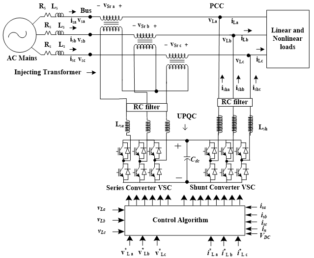 Figure 1: Schematic diagram of 3- Phase 3 Wire AC distribution system connected with UPQC
3.1. Design an Algorithm for Shunt VSC
The discretization of the input signals of SOGI is done to get the exact 900 degree phase shift of input signals. A trapezoidal method is suitable to design the algorithm. The H(z) is the discrete function of Laplace Function (LF) H(s), if it is satisfied by given rule.
where z is z-transformation and Ts is the sampling frequency.
The simplest form of discrete form of SOGI structure [1] is given as,
The quadrature axis voltage (vβ) of general configuration of single phase PLL is estimated as follows,
where a0= , a1=
and a2=
The equation (2) and (3) are used to extract the discrete value of active part of voltage (vα) and reactive part of voltage (vβ). These discrete values are helpful to get real time active power (pL(t)) and reactive power (qL(t)). The pL(t) and qL(t) are estimated as follows,
where pLa and qLa are real time active and reactive powers of phase ‘a’. While, iα active part and iβare a reactive part of input AC current. The AC mains is designed for active power only thus, reactive part in equation (4) is taken as zero. Next stage, AC mains is delivered balanced power which is given as follows
The equation (5) gives load demand of active power per phase. The reference of actual active and reactive part of reference current can find as
The losses in equation (6) is controlled by the DC link power (PDC), which is calculated as,
The DC link of UPQC is controlled by a simple Proportional Integral (PI) controller. The input of PI is an error signal (ε(n)) of DC link voltage. And ε(n) can be extracted by the difference of the reference voltage (v*DC) and actual sensed voltage (vDC(n)). The power loss at nth sampling time is estimated using equation (8).
where kp and ki are gain constants of PI controller. While ε(n) and ε(n-1) sampling time.
Finally, using equation (7) reference currents (isa*, isb*, isc*) can be evaluated as follows,
(9)
However, the pulses of shunt VSC are generated by comparing the equation (9) signals and the signals of 3-phase AC mains currents (isa, isb, isc,).
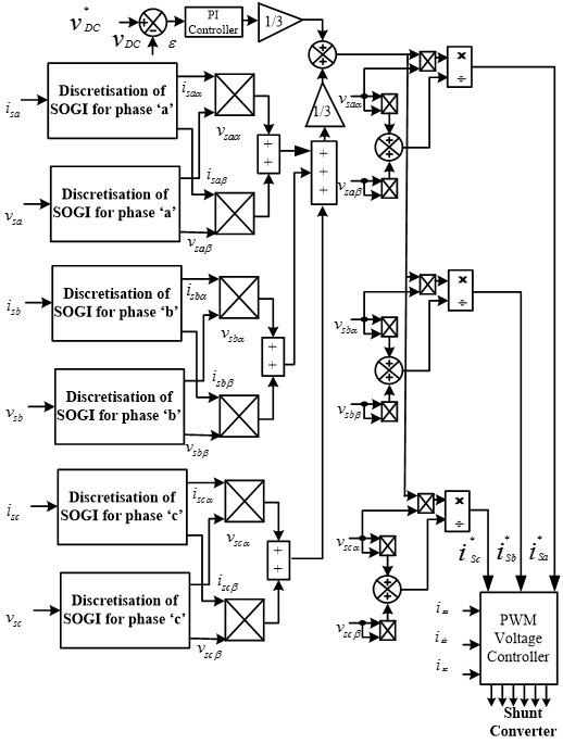 Figure 2: (a) Modified control Algorithm for shunt VSC
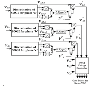 Figure 2: (b) Control Algorithm for series VSC
3.2. Design an Algorithm for series VSC
In Figure 2b, a feedback unit ‘m’ is played a role to design an algorithm of series VSC. Where m gives the proper feedback voltage under sag/swell condition of AC mains voltage. It maintains the desire PCC voltage. The actual PCC voltages are extracted by a simple calculation which is square root sum of direct axis voltage (va,α) and quadrature axis voltage (va,β). These values are further multiplying by 0.5 to get root mean square (rms) value. Moreover, a reference load voltage (VL*) is divided by the actual rms load voltage to obtain the m. Mathematically, m can be obtained as,
Thus, under normal condition m predict a value equal to one to get desire voltage at PCC. This controller is an adaptive in nature. Similarly, m can predict a different correct value under abnormal condition of the AC mains. It is given as follows.
3.2.1 Voltage Sag Condition
In this case, assume, AC mains voltage of phase ‘a’ is running with voltage sag by factor x. Consequently, at PCC the voltage is reduced by factor x. The feedback unit is predicted m1 under voltage sag and it is calculated as follows,
If factor x become one, the m1 is equal to m, hence it is proved by equation (11) that the proposed control algorithm is an adaptive in nature under voltage sag condition. Moreover, the generated reference voltage (v*La,) is equal to multiple of direct axis voltage (vLa,α) and feedback unit (m1*x) under voltage sag condition. Now, v*La can find as,
3.2.2 Under Voltage Swell
In this case, assume, AC mains voltage of phase ‘a’ is running with voltage swell by factor y. Consequently, at PCC the voltage is reduced by factor y. The feedback unit is predicted m2 under voltage swell and it is calculated as follows,
If factor y become one, the m2 is equal to m, hence it is proved by equation (13) that the proposed control algorithm is an adaptive in nature under voltage swell condition. Moreover, the generated reference voltage (v*La,) is equal to multiple of direct axis voltage (vLa,β) and feedback unit (m2*y) under voltage swell condition. Now, v*La can find as,
In the same way, the above equation can extract for phase ‘b’ and phase ‘c’ of primary AC distribution system. The proposed control algorithm can work under abnormal condition of AC mains and it is good to opt for the UPQC.
4. Experimental Results
A 3-phase, 3-wire AC system is integrated with UPQC in the lab which is shown in Figure 3. It consists D-Space software to link with hardware and PC for evaluation the performance of the modified algorithm under polluted loads. In Table 1, model parameters are given. Whereas in Table 2 shows the THD and power factor under various load conditions. The hardware results are shown in Figures 5 and Figures 6&7 under steady state conditions and under dynamic condition respectively. Moreover, a comparative Matlab result is shown in Figure 4 to understand the value of modified algorithm.
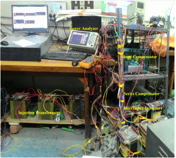 Figure 3: A lab model of 3-phase 3-wire AC system integrated with UPQC
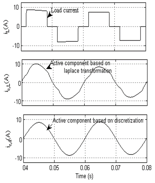 Figure 4: a comparatives results under quasi square wave demand of load current, (a) polluted load current waveform (iL(A)), (b) AC mains current waveform under SOGI (ic,L(A)) and AC mains current under modified SOGI (ic,d(A)).
Table 1: Practical Parameters
| Quantities | Value |
| PCC line voltage | 110V |
| Frequency | 50Hz |
| Load | 819VA |
| Load current THD | 20%; |
| DC-bus Voltage | 180V |
| DC-bus Capacitor | 3.3 mF |
| Shunt converter Interfacing Inductors | 8 mH |
| Ripple Filter | 10 μF, 10 Ω |
| Series Converter Interfacing Inductor | 1.5 mH |
| DC-bus PI Gains | Kp = 4, Ki = 1 |
| Gain constant | K=1 |
| ao | 1.5698*10-4 |
| a1 | 1.99984 |
| a2 | -0.999764 |
 (a) The line to line voltage and Phase currents abc at AC mains under normal condition
 (b) The line to line voltage and Phase currents abc at PCC under normal condition
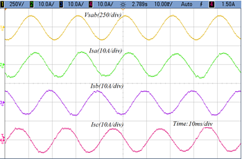
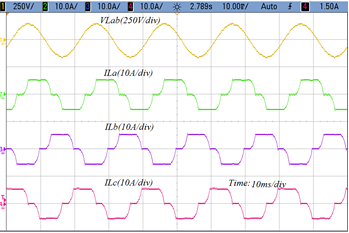
Figure 5: The AC mains voltage, currents, load voltage and load currents under normal condition.
4.1. Performance Under Normal Condition
The power analyzer 3-phase 4 channel is used to show the results of modified algorithm. The line to line voltage vsab and 3-phase AC mains current are indicated as isa, isb, and isc respectively. It is shown in Figure 5(a) whereas in Figure 5(b), the line to line load voltage vLab and single phase load current are indicated as iLa, iLb, and iLc. It is observed from the results that source AC mains are free from harmonics while load is under heavy polluted thus, shunt algorithm works properly. Whereas, series algorithm maintain desired voltage at PCC properly under steady state condition.
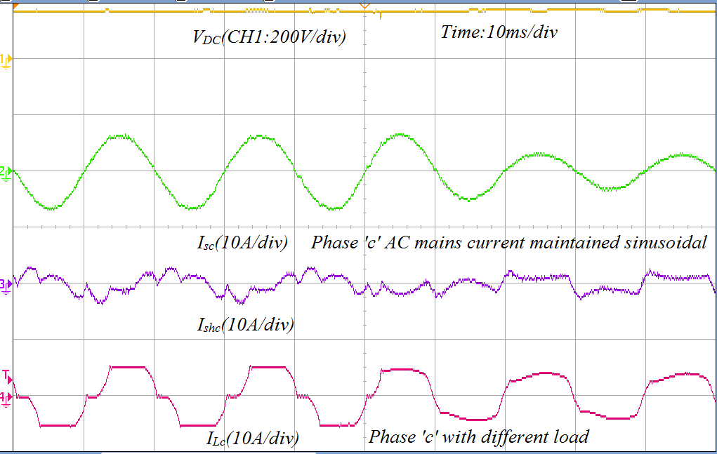
4.2. Performance Shunt VSC Under Dynamic Condition
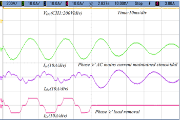
In Figure 6(a), performance of modified control algorithm for shunt VSC is presented under dynamic load condition. In this case, phase ‘c’ of load is abruptly off. Thus, load current iLc is zero and at the same time shunt VSC become active and inject shunt current ishc in phase ‘c’ to stable the AC mains source current isc . Whereas, in Figure 6(b), when load demands current in phase ‘c’ active, the shunt VSC injects harmonics to make supply pure sinusoidal AC mains current. It is seen that the modified control algorithm works properly to maintain AC mains source as an international standard and balanced. Moreover, the DC link voltage (VDC) is unchanged under dynamics condition of load.
 (a) Performance of shunt converter under zero load
 (b) Performance of shunt converter under dynamic load
Figure 6: Current waveform of AC main current, shunt current and load current under dynamic condition
4.3. Performance Series VSC Under Dynamic Condition
The performance of series VSC is shown in Figures 7(a)-(b) and Figures 7(c)-(d) under voltage sag and swell conditions. In Figure 7(a), AC mains line to line voltage vsab is running under voltage sag while at PCC line to line voltage vLab is regulated to maintain the desire voltage of the load. The series voltage vsrab is added in series with the AC mains to regulate load voltage at 110V using series VSC.
In Figure 7(b), AC mains 3-phase voltages are regulated by series VSC. The line to line voltage vsab and vsbc are running under voltage sag condition whereas line to line load voltage vLab and vLbc are regulated at desire voltage 110V. Thus, the waveform of three phase voltage shows that the performance of feedback unit ‘m’ works satisfactory and series VSC works at desire level to mitigate voltage sag.
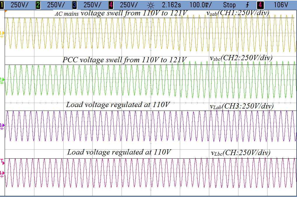
Moreover, the feedback factor ‘m’ is tested under voltage swell condition. In this case, series VSC injects voltage in feeder of AC mains to opposite phase of AC mains voltage. It suppresses the AC mains voltage and consequently load voltage is maintain at desire level 110V. In Figure 7(c), AC mains vsab is running under voltage swell while at PCC vLab is regulated to maintain the desire voltage of the load. The series voltage vsrab is substract in series with the AC mains to regulate load voltage at 110V using series VSC. While, AC mains current isa reduces under voltage swell condition to balance the power of the AC mains.
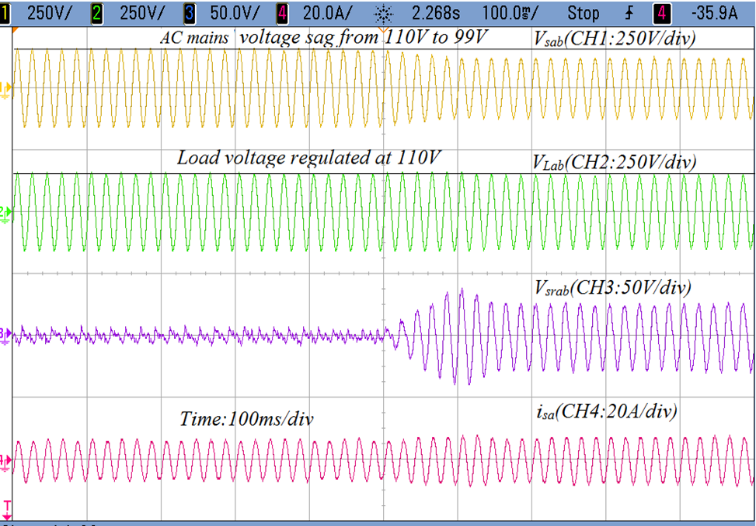 (a) Performance of series converter under voltage sag
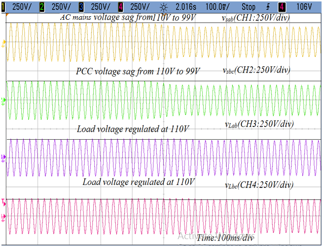 (b) Regulated voltage of three phase load under voltage sag
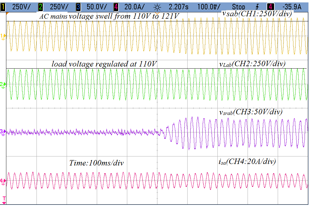 (c) Performance of series converter under voltage swell
 (d) Regulated voltage of three phase load under voltage swell condition
Figure 7: Voltage waveforms of AC mains voltage, load voltage and series converter voltage under dynamic condition
In Figure 7(d), AC mains 3-phase voltages are regulated by series VSC. The vsab and vsbc are running under voltage swell condition whereas vLab and vLbc are regulated at desire voltage 110V. Thus, the waveform of three phase voltage shows that the performance of feedback unit ‘m’ works satisfactory and series VSC works at desire level to mitigate voltage swell.
5. Conclusion
The discrete value of second order generalized integrator (SOGI) has realized to design control approach of UPQC which performance have been verified under heavy polluted load and under various conditions of load. Under normal condition, series VSC is inactive while shunt VSC eliminate the harmonics of the load and injects reactive power demand to the 3-phase load. And under dynamic condition, the shunt VSC shows the excellent performance whereas the series VSC works under voltage sag and swell conditions. The voltage sag from 110V to 99V while voltage swell from 110V to 121V are generated at AC mains while at load side (PCC) the voltage is regulated at 110V. The performance of proposed feedback unit ‘m’ for series part of UPQC has unique to suppress the sag and swell voltage of PCC and modified algorithm of shunt part of UPQC eliminates the harmonics of load and enhance the performance of AC mains. Thus, it has been seen that proposed algorithm of UPQC improve the multiple power quality of the 3-phase primary distribution feeder line of power system.
Table 2: THD and Power Factor Under Various Load Conditions
| Parameters | Nominal | Sag | Swell |
| Load Current THD | 20% | 20.14% | 19.80% |
| PCC Current THD | 3.77% | 2.88% | 4.65% |
| Load Voltage THD | 3.58 | 3.50% | 3.55% |
| PCC Voltage THD | 1.92 | 1.96% | 1.9% |
| Power factor at grid | 0.99 | 0.99 |
- M. Hasan, B. Singh and S. Devassy, “Modified Control Technique for Series and Shunt Converters of UPQC to Enhance Power Quality,” in 2020 IEEE 9th Power India International Conference (PIICON), SONEPAT, India, 2020, 1-6, doi: 10.1109/PIICON49524.2020.9113056.
- M. Hasan, A. Q. Ansari and B. Singh, “Parameters estimation of a series VSC and shunt VSC to design a unified power quality conditioner (UPQC),” 2015 39th National Systems Conference (NSC), Greater Noida, India, 2015, 1-6, doi: 10.1109/NATSYS.2015.7489111.
- S. Devassy and B. Singh, “Performance Analysis of Solar PV Array and Battery Integrated Unified Power Quality Conditioner for Microgrid Systems,” in IEEE Transactions on Industrial Electronics, 68(5), 4027-4035, 2021, doi: 10.1109/TIE.2020.2984439.
- M. Hasan, B. Singh and A. Q. Ansari, “An approach to minimize the VA size of UPQC-S and its performance comparison,” 2018 IEEMA Engineer Infinite Conference (eTechNxT), New Delhi, 2018, 1-5, doi: 10.1109/ETECHNXT.2018.8385344.
- A. Q. Ansari, B. Singh and M. Hasan, “Algorithm for power angle control to improve power quality in distribution system using unified power quality conditioner,” in IET Generation, Transmission & Distribution, 9(12), 1439-1447, 2015, doi: 10.1049/iet-gtd.2014.0734.
- S. Chandrakala Devi, B. Singh and S. Devassy, “Modified generalised integrator based control strategy for solar PV fed UPQC enabling power quality improvement,” in IET Generation, Transmission & Distribution, 14(16), 3127-3138, 2020, doi: 10.1049/iet-gtd.2019.1939.
- M. Hasan – Handbook of Research on Power and Energy System, Application of Power Electronics in Power Systems, 2018, page 31 DOI: 10.4018/978-1-5225-3935-3.ch010
- S. Devassy and B. Singh, “Implementation of Solar Photovoltaic System With Universal Active Filtering Capability,” in IEEE Transactions on Industry Applications, 55(4), 3926-3934, 2019, doi: 10.1109/TIA.2019.2906297.
- M. Karimi-Ghartemani, H. Karimi and M. R. Iravani, “A magnitude/phase-locked loop system based on estimation of frequency and in-phase/quadrature-phase amplitudes,” in IEEE Transactions on Industrial Electronics, 51(2), 511-517, 2004, doi: 10.1109/TIE.2004.825282.
- B. Trento, L. M. Tolbert and D. Costinett, “Grid synchronization using fixed filtering with magnitude and phase compensation,” 2014 IEEE Energy Conversion Congress and Exposition (ECCE), Pittsburgh, PA, 2641-2647, 2014, doi: 10.1109/ECCE.2014.6953755.
- M. S. Reza, M. Ciobotaru and V. G. Agelidis, “Tracking of time-varying grid voltage using DFT based second order generalized integrator technique,” 2012 IEEE International Conference on Power System Technology (POWERCON), Auckland, 1-6, 2012, doi: 10.1109/PowerCon.2012.6401432.
- T. Ngo, S. Biricik, and M. Basu, “A Self-tuning Grid Synchronization Method for Active Power Filters,” Electric Power Components and Systems, 44(17), 1-11, 2016, doi.org/ 10.1080/15325008.2016.1200696.
- W. Li, X. Ruan, C. Bao, D. Pan and X. Wang, “Grid synchronization systems of three-phase grid-connected power converters: A complex vector filter perspective,” IEEE Trans. Ind. Elect., 61(4), 1855–1870, 2014, doi.org/10.1109/TPEL.2011.2158238.
- S. Biricik, S. Redif and M. Basu, “Voltage Sensorless Control of Single-phase Active Power Filter Based on the Second-order Generalized Integrator Algorithm,” Electric Power Components and Systems, 43(7) 820–827, 2015, doi.org/ 10.1080/15325008.2014.100359.
- F. U. Nazir, N. Kumar, B. C. Pal, B. Singh and B. K. Panigrahi, “Enhanced SOGI Controller for Weak Grid Integrated Solar PV System,” in IEEE Transactions on Energy Conversion, 35(3), 1208-1217, 2020, doi: 10.1109/TEC.2020.2990866.
- P. Chittora, A. Singh and M. Singh, “Simple and efficient control of DSTATCOM in three-phase four-wire polluted grid system using MCCF-SOGI based controller,” in IET Generation, Transmission & Distribution, 12(5),1213-1222, 2018, doi: 10.1049/iet-gtd.2017.0901.
- S. Devassy, B. Singh. “Modified p-q Theory Based Control of Solar PV Integrated UPQC-S”, IEEE Transactions on Industry Applications, 53(5), 5031-5040, 2017, doi: 10.1109/TIA.2017.2714138.
- C. Zhang, X. Zhao, X. Wang, X. Chai, Z. Zhang and X. Guo, “A Grid Synchronization PLL Method Based on Mixed Second- and Third-Order Generalized Integrator for DC Offset Elimination and Frequency Adaptability,” in IEEE Journal of Emerging and Selected Topics in Power Electronics, 6(3), 1517-1526, 2018, doi: 10.1109/JESTPE.2018.2810499.
- C. M. Nirmal Mukundan, P. Jayaprakash, U. Subramaniam and D. J. Almakhles, “Binary Hybrid Multilevel Inverter-Based Grid Integrated Solar Energy Conversion System With Damped SOGI Control,” in IEEE Access, 8, 37214-37228, 2020, doi: 10.1109/ACCESS.2020.2974773.
- N. Kumar, I. Hussain, B. Singh and B. K. Panigrahi, “Implementation of Multilayer Fifth-Order Generalized Integrator-Based Adaptive Control for Grid-Tied Solar PV Energy Conversion System,” in IEEE Transactions on Industrial Informatics, 14(7), 2857-2868, 2018, doi: 10.1109/TII.2017.2777882.
- A. Nabae and T. Tanaka, “A new definition of instantaneous active-reactive current and power based on instantaneous space vectors on polar coordinates in three-phase circuits,” in IEEE Transactions on Power Delivery, 11(3),1238-1243,1996, doi: 10.1109/61.517477.
- H. Fujita and H. Akagi, “The Unified Power Quality Conditioner: The Integration of Series- and Shunt-Active Filters”; IEEE Trans. On Power Electronics, 12(2), 315–322, 1998, doi:10.1109/63.662847
- M. Monfared, M. Sanatkar, and S. Golestan. “Direct active and reactive power control of single-phase grid-tie converters.” IET Power Electronics, 5, 1544-1550, 2012, doi.org/10.1049/iet-pel.2012.0131
- M. Ciobotaru, R. Teodorescu and F. Blaabjerg, “A new single-phase PLL structure based on second order generalized integrator,” 2006 37th IEEE Power Electronics Specialists Conference, Jeju, Korea (South), 1-6, 2006, doi: 10.1109/pesc.2006.1711988.