BLDC Motor Vibration Identification by Finite Element Method and Measurements

Adv. Sci. Technol. Eng. Syst. J. 6(2), 784–789 (2021);
 DOI: 10.25046/aj060290
Within the results of scientific research, vibrations and their reduction have been described for the brushless direct current motor with permanent magnets (BLDC motor). In this paper, calculations (the finite element method using commercial Finite Element Software Ansys) and measurements were performed to identifying the sources of vibrations in BLDC motor. The article presents numerical and experimental research on the resonant frequencies of the stator and the rotor; transient vibrations of the stator due to Maxwell forces in the motor have been analysed. It was shown that the natural frequencies were the main source of vibrations. The vibration sources indentification made possible formulation of better principles of choice of constructional motor parameters with the aim of attaining minimalization of vibrations.
1. Introduction
Due to the high efficiency, electrical BLDC motors are becoming more widely used within the framework of practical applications. In this field, development of new permanent magnets with the very big energy density is additionally of great importance [1]. The large and impressive technical progress within rotating electrical machines is connected with dynamical extension of power electronics converters. For motors there is possible the modern speed control on a large range. Present-day instantaneous torque/flux control makes possible considerable improving the electrical machines operation. For practical applications, disadvantage of PWM inverters consists in enlargement of the overall motor noise. Here it can be noticed that the special variant is substantial when the phenomenon of resonance appears within the framework of supply harmonics and resonant frequencies of machine’s parts. Designers of electric motors ought to undertake an obligation to create less noisy devices [2].
Magnetic sources of vibrations in BLDC motor are caused by Maxwell forces, cogging torque ripple and torque ripple [3, 4]. If the natural frequencies of the stator or the rotor coincide with frequencies of magnetic forces or torque ripple resonance may occur. Also, as a result of imperfections of construction or assembly, rotor eccentricity can occur and distortion of the magnetic field may appear. Owing to this disadvantageous situation, the magnetic force distribution changes and the unbalanced magnetic force exists [5]. Vibrations can also be due to friction of different parts of machine, e.g. bearings. Aerodynamic noise is generated by the circulation of the cooling medium of the machine.
In literature analytical methods have been also used to describe mathematically Maxwell magnetic forces harmonics taking into consideration both the spatial and time frequency order [3]. For correct designing, the best numbers of slots were found and given in order to attain avoidance of low harmonic radial forces and considerable reduction of vibrations.
The numerical investigation to predict vibrations are based on creation of magnetical and mechanical finite element models [6]. According to the general strategy within the scientific methodology, authenticity of research work may be realized by comparing numerical results with experimental ones. In the magnetic motor model the flux distribution in air-gap and the cogging torque–obtained by calculations – are compared with measurements. In the case of the mechanical model natural vibrations frequencies are compared for theoretical and practical activities. Among other things the accuracy of calculated results depends on proper modeling of magnetic, mechanical and acoustic parameters of the motor structure and the quality of the model of the numerical mesh. The magnetic forces can be minimized by optimizing changes within the geometric parameters of the magnetic circuit.
In literature concerning modern power electronics it was shown that the selecting appropriate strategies of Pulse Width Modulation (PWM) could ensure avoidance of the mechanical resonance [2]. For the other example it was illustrated that geometrical modification of the rotor was the effective method to increase natural frequencies and by this constructional way the phenomenon of resonance has been eliminated [7].
2. BLDC motor and magnetic calculations
2.1. The BLDC motor
Taken to theoretical and practical investigations electronically controlled BLDC motor, with the stator having concentrated windings and with the interior rotor possessing permanent magnets, has been presented as three separate parts in Figure 1. The specification of characteristic parameters and different data of the motor are presented in paper [8].
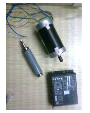 Figure 1: The analysed BLDC motor (stator, rotor) with PWM converter for power supply
Within the fundamental governing equations there is the Maxwell’s equation [9]:
rot H = J (1)
where H is the magnetic intensity, J – the current density.
In accordance with Gauss’s Law, taking into account divergence theorem we have for the magnetic flux density B the following relation:
div B = 0 (2)
The relationship between inducing field strength and magnetization intensity is given by:
B = μ H (3)
where µ is the magnetic permeability.
The current density distribution of the coil is here described as follows:
J = 1 ∙ Jz (4)
Numerical solution of 2-D magnetostatic problem is based on the equation:
∆2 Az = μ Jz (5)
The outer boundary of the stator yoke has been applied for all outer nodes of the stator yoke:
Az (x, y) = Az1 (x, y) = 0 (6)
The stress tensor method is used for calculation of the magnetic force.
2.2. Magnetic field results
Within the framework of computations concerning the finite element methodics, several assumptions are here taken into consideration. The magnetic field reckoning is performed using the principles connected with the magnetostatic analysis.
For the 2-D FEM model, the BLDC motor is fed with rectangular wave current The rotor is rotating at one mechanical degree of freedom.
The two-dimensional model for magnetic field calculations is shown in Figure 2 (so-called geometrical model) and in Figure 3 (here it is the numerical mesh – the quarter of the model).
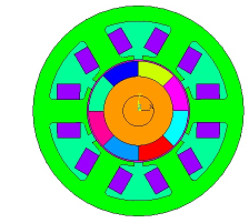 Figure 2: Geometrical model of BLDC 6/8 motor (6 – stator teeth, windings and rotor with 8 – magnets applied)
Figure 4 presents the distribution of the tangential and radial flux densities in motor air-gap. By other means and for the selected rotor position, Figure 5 illustrates the calculated magnetic flux distribution.
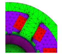 Figure 3: Numerical mesh of the magnetic model: stator (the part of stator iron, windings) and rotor with magnets (1/4 of the BLDC motor model)
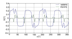 Figure 4: Radial (rad) and tangential (st) flux densities distribution in the middle of the air-gap in BLDC motor
The Maxwell forces variations identify the mode orders in the electrical machine. The dominant mode shapes are associated with Maxwell force distribution in the air-gap shown in Figure 6. On the ground of detailed analysis of diagrammatic presentation in Figure 6, it can be noticed that the general pattern is repeated twice; here the lowest order of radial force and dominant mode order are equal two [10]. It means that the most important circumferential modes of vibrations of the stator are the second and fourth mode of natural frequencies.
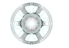 Figure 5: Magnetic flux distribution in BLDC motor
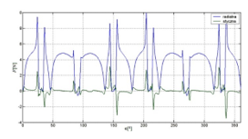 Figure 6: The magnetic forces radial and tangential distribution acting on stator poles in the air-gap in BLDC model
3. Modal analysis
3.1. Modal analysis of stator
Two important reasons: determination of the natural frequency and recognition of the mode shape of structure are the sought purpose of modal analysis. We are interested in characteristics of a structure’s dynamics connected with varying loads.
The equation for the free vibrations of the undamped system can be expressed in matrix notation as follows [11]:
{[K] – ω2 [M]} {u} = 0 (7)
where: [K] – stiffness matrix, [M] – mass matrix, ω – angular frequency, u – displacement matrix. Frequencies: f = ω / 2π and displacement matrix: u are the solutions of the equation (7).
The natural frequencies of vibrations can be excited by radial Maxwell forces acting on the stator poles. The maximum amplitude of vibrations occurs for resonance when the excitation frequency matches with the natural frequency of the motor and the spatial distribution of Maxwell force is similar to one of the mode of the natural frequencies of the stator.
The numerical calculations using Lanchos algorithm of the natural frequencies were performed for two various stator’s models: only alone core in the first variant and the core with the winding in the second case. Within such methodics the stator core is modeled as steel. However in literaturę it was shown that the influence of windings on vibrations could be also important [12]. Because of the complex structure, windings can be taken into account in simplifying manner by adding mass or by increasing density of stator teeth [13].
To realize calculations with the using finite element method (FEM) and allowing for windings, density of stator teeth has been increased by such manner to accomplish finally the smallest possible error for the dominant second and fourth mode. The compromise value of the density was determined as the following value: ρ = 1000 kg / m3.The selected result is given in Figure 7.
Here it ought to be underlined that – despite of efforts – taking windings in a simplified way in the physical model into consideration causes some errors for other modes of natural frequencies of stator (Table 1). Experimental studies using hammer impact method were conducted to verify the results of the numerical calculations and the radial vibrations were recorded using accelerometers Brüel & Kjær. The results have been given in Figure 8. The comparison between numerical results and outcomes of measurements can be realized on the ground of data given in Table 1.
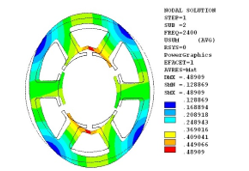 Figure 7: Modal analysis results of the for stator core with windings modelled by increasing stator density (r=2, f=2400Hz)
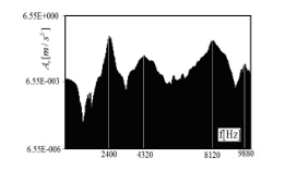 Figure 8: The natural frequencies of the stator – radial acceleration Ar [m / s2] of stator structure obtained by hammer impact method
Table 1: Natural frequencies of the stator [Hz]
| Mode order | FEM
– stator yoke |
FEM
– stator yoke with windings |
Measurements
(stator yoke with windings) |
| 1 | 3026 | 2400 | 2400 |
| 2 | 4024 | 5366 | 4320 |
| 3 | 6753 | 7101 | 8120 |
| 4 | 12600 | 10223 | 9880 |
3.2. Modal analysis of rotor
The numerical calculations of the natural frequencies using Lanchos algorithm were performed for two cases: the first variant of the separate rotor and the second case of the rotor with bearings modeled as spring elastic – damping element. The selected result is given in Figure 9.
The shaft is made of steel and ferrite magnets. Calculations were performed for different stiffness to elastic – damping element to fit the measurements best of all [7]. Experimental studies using shaker method were conducted to verify the results of the numerical results and the radial vibrations were recorded using accelerometers Brüel & Kjær by [11]. The obtained exemplary results of calculations and measurements using shaker methods are presented in Table 2.
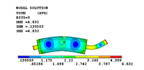 Figure 9: Modal analysis of rotor model without bearings – numerical results bending mode, f = 9766 Hz
Table 2: Calculation bending natural frequencies of the rotor [Hz] for different stiffness of bearings and measurements
| Mode of deformation | FEM – 106 [N/m] | FEM -107 [N/m] | Measurements |
| first bending mode | 4019 | 4136 | 3950 |
| second bending mode | 9770 | 9797 | 10550 |
4. Magnetic forces and transient analysis
The magnetic forces depend on the number of teeth, the number of poles and the speed of rotation. The frequencies of magnetic forces in 3-phase BLDC motor can be calculated as follows [4]:
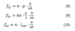 where: n – arbitrary integer, p – number of pairs of poles, – number of stator slots, N – rotor velocity [rpm]. The rotation speed was chosen to be 4000 rpm. The first frequencies of Maxwell forces, torque ripple and cogging torque are equal: = 533 Hz, = 800 Hz, = 711 Hz.
The transient analysis is governed by the following equation [9]:
![]() where: – mass matrix, – stiffness matrix, – vector of displacement; – damping matrix. Newmark method has been employed for differential equation solution. The calculations were carried out for the rotor velocity N = 4000 rpm. Magnetic forces calculated in magnetic analysis are loads in the mechanical analysis. In keeping with the energy absorbing in the constructional structure of the BLDC motor, mainly due to the windings, structural damping has been presented [9]. However due to to lack of the experimental data damping are assumed to zero. The maximum amplitude of vibration occurs near the resonant frequencies the second and fourth natural frequency of the stator. The results are given in Figure 10 and Figure11. The stator deformation due to magnetic forces during no-load for selected time-steps are presented (Figure 12 and Figure 13).
where: – mass matrix, – stiffness matrix, – vector of displacement; – damping matrix. Newmark method has been employed for differential equation solution. The calculations were carried out for the rotor velocity N = 4000 rpm. Magnetic forces calculated in magnetic analysis are loads in the mechanical analysis. In keeping with the energy absorbing in the constructional structure of the BLDC motor, mainly due to the windings, structural damping has been presented [9]. However due to to lack of the experimental data damping are assumed to zero. The maximum amplitude of vibration occurs near the resonant frequencies the second and fourth natural frequency of the stator. The results are given in Figure 10 and Figure11. The stator deformation due to magnetic forces during no-load for selected time-steps are presented (Figure 12 and Figure 13).
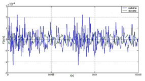 Figure 10: Numerical transient analysis of stator vibrations due to magnetic forces – velocity versus time V [m/s] – radial (blue) and tangential velocity (green) for selected outer node
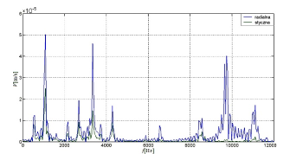 Figure 11: Numerical transient analysis – Fourier analysis of radial velocity for selected outer stator node of stator V [m/s] – radial (blue) and tangential velocity (green)
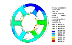 Figure 12: Numerical transient analysis – the stator deformation and displacement U [m] for selected time-step
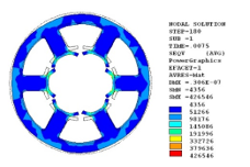 Figure 13: Numerical transient analysis of stator deformation and Von Mises stress σeqv [Pa] for selected time-step
5. Measurements of BLDC in no-load mode
Experimental studies were conducted to verify the numerical results. The rotation speed in no-load mode was equal 4000 rpm. The maximum oscillation amplitude occurs near the natural frequencies of the stator (second mode vibration: f = 2960 Hz and fourth mode vibration: f = 10020 Hz) and rotor (second bending mode of rotor: f = 10550 Hz measured for the rotor placed within the motor structure by shaker method) – Figure 14. Here it is advisable to make a note of additional information that the investigated motor was suspended by elastic springs. The current was recorded in no-load mode and its Fourier transformation is presented in Figure 15. It can be noticed that the vibrations spectrum was similar for different values of velocity of the rotor. The main sources of vibrations are resonant frequencies excited by magnetic forces and in keeping with different electric machine imperfections creating harmonic forces exciting the bending mode of the rotor [3]. It may be concluded from comparison of Fourier analyses (FFT). In Figure 14 this analysis is realized within the radial velocity of vibrations however in Figure 15 the current of the motor stator can be investigated.
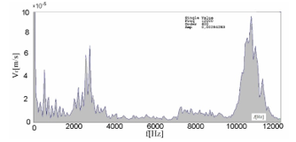 Figure 14: Measurement of stator vibrations – Fourier analysis of radial velocity Vr [mm/s] for selected point
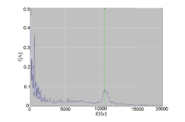 Figure 15: Measurement of current supply I [A] of BLDC motor during no-load mode – Fourier analysis
6. Conclusions
Due to the high efficiency, electrical BLDC motors are becoming more widely used as torque motors in control. systems and instrumentation. One of the disadvantages of BLDC motor is the increase in noise due to the use of PWM converters, so the study of the possibilities of reducing motor noise is an important problem. The article investigated the natural frequencies of the stator and the rotor, as well as the possibility of resonance due to coincidence of the frequency of magnetic forces and the pulsation of the motor torque with natural vibrations of the stator or rotor.
The study of the magnetic forces in the air gap using the finite element method allowed us to determine the main modes of the magnetic forces, the influence of which can lead to the occurrence of resonance and an increase in motor noise. The analysis of the natural frequencies of the stator was carried out on the basis of the equation of free oscillations without taking into account damping. The influence of the windings was taken into account in a simplified way, by adding mass to the stator by increasing density of stator teeth, which led to a small error for most important circumferential modes of vibration of the stator (the second and fourth mode natural frequencies) and significant error in comparison with the experimental results for the other natural frequencies.
The natural frequencies of the rotor were also determined by comparing experimental and numerical results calculated for different stiffness values of the bearings implemented as spring elastic – damping elements.
Transient stator vibrations due to magnetic forces were depending on the number of teeth, the number of poles, and the speed of rotation. The rotation speed was equal 4000 rpm. Experimental studies were conducted to verify the results. The maximum oscillation amplitude occurs near the natural frequencies of the stator and rotor. Hence, it is concluded that the main sources of vibration are the natural frequencies of the motor.
During motor operation and rotation of the rotor, the form of the stator vibrations may change the dominant order of mode. These scientific results should be taken into account when designing the BLDC motor.
Conflict of interest
The authors declare no conflict of interest.
Acknowledgment
The computations were performed PLGrid infrastructure.
- J. Gieras, Permanent magnet motor technology: design and applications”, 3rd ed. Taylor and Francis Group, ISBN 978-1-4200-6440-7, 2010.
- J. Besnerais et al., “Prediction of Audible Magnetic Noise Radiated by Adjustable-Speed Drive Induction Machines”, IEEE Transactions on Industry Applications, 46(4), 1367-1373, 2010, doi: 10.1109/TIA.2010.2049624.
- J. Besnerais et al., “Analysis of the electromagnetic acoustic noise and vibrations of a high-speed brushless DC motor,” 8th IET International Conference on Power Electronics, Machines and Drives (PEMD 2016), Glasgow, UK, 1-10, 2016, doi: 10.1049/cp.2016.0284.
- H.J. Lee et al., Noise source identification of a BLDC motor”, Journal of Mechanical Science Technology”, 22(708), 2008, doi: 10.1007/s12206-008-0110-9.
- U. Kim et al., “Effects of magnetically induced vibration force in brushless permanent-magnet motors”, IEEE Transactions on Magnetics, 41(6), 2164-2172, 2005, doi: 10.1109/TMAG.2005.847628..
- M. Furlan et al., “The Magnetic Noise of a DC Electric Motor – Modeling of Three-Times-Coupled Electromagnetic, Mechanical and Acoustic Phenomena”. In: Wiak S., Krawczyk A., Trlep M. (eds) Computer Engineering in Applied Electromagnetism. Springer, Dordrecht, 2005, doi: 10.1007/1-4020-3169-6_48.
- J.D. Ede et al., “Rotor resonances of high-speed permanent-magnet brushless machines”, IEEE Transactions on Industry Applications, 38(6), 1542-1548, 2002, doi: 10.1109/TIA.2002.804765.
- J. Podhajecki, “Numerical and experimental vibration analysis of BLDC motor”, 19th International Symposium on Electromagnetic Fields in Mechatronics, Electrical and Electronic Engineering (ISEF), Nancy, France, 1-2, 2019, doi: 10.1109/ISEF45929.2019.9096907.
- A. Belahcen, Magnetic Forces and Magnetostriction in Electrical Machines”, 951-22-7183-4, 2004.
- M. Islam et al., “Noise and vibration characteristics of permanent magnet synchronous motors using electromagnetic and structural analyses”, IEEE Energy Conversion Congress and Exposition, Phoenix, AZ, USA, 3399-3405, 2011, doi: 10.1109/ECCE.2011.6064228.
- J.P. Lecointe et al., Five methods of stator natural frequency determination: Case of induction and switched reluctance machines”, Mechanical Systems and Signal Processing. 18, 1133 – 1159, 2004, doi: 10.1016/j.ymssp.2003.08.002.
- W. Cai, “Impact of stator windings and end-bells on resonant frequencies and mode shapes of switched reluctance motors”, IEEE Transactions on Industry Applications, 38(4), 1027-1036, July-Aug. 2002, doi: 10.1109/TIA.2002.800594.
- C. Schlensok, Electromagnetically excited audible noise – Evaluation and optimization of electrical machines by numerical simulation”, COMPEL: The International Journal for Computation and Mathematics in Electrical and Electronic Engineering, 26, 727-742, 2007, doi: 10.1108/03321640710751181.