
Controlling A Multiphase Induction Motor with Multilevel Converter Paradigm
Volume 6, Issue 2, Page No 641-645, 2021
Author’s Name: Majeed Rashid Zaidana)
View Affiliations
Department of Electrical Technologies, Baqubah Tech. Institute, Middle Technical University, Baghdad, 10011, Iraq
a)Author to whom correspondence should be addressed. E-mail: majeedrzn@mtu.edu.iq
Adv. Sci. Technol. Eng. Syst. J. 6(2), 641-645 (2021); ![]() DOI: 10.25046/aj060274
DOI: 10.25046/aj060274
Keywords: Induction Motor, PPM, PWM, Inverter, Control, Torque, RPM

Export Citations
Induction motors (IM) are used widely in high energy applications where high torque is required such as ships/ aircrafts manufacturing industry. Those motor drivers are populated in many advantages especially their wide control strategies. However, new technology is invented for enhancing efficiency and smoothing the torque curve by increasing number of phases in the motor drive. Speed control can be achieved by changing the pole numbers between any two different phases using pole-phase modulation (PPM). The problem is raised when a large number of phases are used to enhance the voltage profile. This problem is manifested in the complexity of control and complexity of hardware (more devices need to be involved) which increases the cost and degrades the performance. This paper argues using a multilevel inverter to produce an enhanced voltage profile and motor speed control without needing to increase the number of devices. The performance of the proposed model is compared with conventional models in terms of efficiency, power factor, speed, torque ripple, and ripple frequency. Results obtained using multilevel inverter based induction motors are found optimum.
Received: 15 August 2020, Accepted: 07 February 2021, Published Online: 20 March 2021
1. Introduction
Induction motors (IM) are widely used in high power applications more likely in aircraft engines, ships tractions, and other heavy industrial applications [1]. The main requirement of heavy industrial applications is a motor with high fault tolerance. The fulfillment of fault tolerance requirement is ensured using polyphase (multiphase) induction motors [2]. However, in contrast with high energy applications, multiphase induction motors drives are the state of the art. Performance of such drivers witnesses good improvement after applying two levels of inverter. Hence, experiments are continued to examine multilevel inverter impact on (multiphase) induction motors drives performance. These motors are inherited the same performance of three-phase induction motors such as high efficiency and low ripple of torque [3]. A mains-fed three-phase cage induction motor still dominates in industrial applications worldwide more than a century after its invention.
As the induction motor is a significant consumer of electrical energy globally, more stringent criteria are regularly imposed on its manufacturers, primarily in terms of the efficiency but also in terms of NVH (noise, vibration, harshness) requirements, [4]. Pole changing techniques are inbuilt prosperities of induction motors give it a flexible speed control capability. Pole changing technique is performed in either of pole phase modulation or pole amplitude modulation. The control strategy of three-phase IM is achieved using v/f control vector, the same can be extended for multiphase motors controlling. The two-level excitation of voltage in multiphase IM is realized improved due to enhanced efficiency of such machines that lie on their smooth torque curve and minimized losses [5]. High starting torque can be achieved even with IM of a smaller number of phases by increasing the poles number using the pole phase modulation technique. A higher number of poles might worsen the case more likely degrades in performance might be happening due to high pole number. The performance degradation can be observed by realizing the torque curve ripple, ripple is likely raising due to high number of poles. One of the feasible solutions for tackling this degradation in three-phase IM is proposed by employing multilevel inverters. Multilevel inverters show good performance in reducing torque level and improving machine efficiency. The technique of multilevel inverter already exists on three-phase machines for performance-related support; furthermore, multilevel inverter is used in multiphase machines as well [6]. The complexity of control strategy and a large number of devices in multiphase machines have triggered another sort of performance degradation. In this paper, we utilized the fact that phase effective voltage is represented by total profile coins voltages [7]. This can be further utilized to create multilevel voltage in the phase without needing to increase the pole number by using a two-level inverter. The strength of this approach is smoothening the torque curve by improving machine efficiency and tackling the computational complexity of the control strategy. Calculations of control vectors in this case can be tackled using data processors such as FPGA chips. Pole phase modulation is further used along with the mentioned approach for applying more consistency on the system without involving a large poles number.
2. PPM Technology
PPM is one of the leading methods to provide motor speed control by changing the excitation voltage phase, this change is impacting the pole pitch and hence continuously reforming the speed ratio. The same concept can be derived using K slotted squirrel cage multiphase induction motor. Assuming an induction motor with two phases (P1 and P2) and two poles (b1 and b2); those stand for two possibilities of phase and pole combination which is used to control speed of IM. So-to-say, the number of slots can be given as below:
![]() Hence, the slot can be represented by the second pole and second phase terms as following:
Hence, the slot can be represented by the second pole and second phase terms as following:
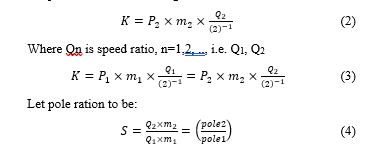 If pole 2 > pole 1 then the term S will either equal to 1 or greater than 1. Let the design of pole-phase modulation to be as in table 1. K is obtained according to the above formula.
Table 1: Pole-phase modulation proposed designs
| Possibilities | M1 | P1 | Q1 | M2 | P2 | Q2 | K |
| PPM 1 | 4 | 3 | 1 | 6 | 2 | 1 | 12 |
| PPM 2 | 5 | 4 | 2 | 2 | 10 | 2 | 20 |
According to table 1, two designs are proposed namely: PPM1 and PPM 2. However, in first design, the pole is changing between three and two with applicable pole phase modulation between four phases to six phases. Whereas, at design 2, the pole is changing between four to ten with pole phase modulation between five phases and two phases. The same is demonstrated in Figure 1.
Looking on the pole-phase combination at both designs, the combination is led to different pole width generation and that must be avoided. The same can be prevented the pole ration i.e. P2/P1 must yield an odd positive integer number. In order to do so, the ratio S must equal the following term. Where x∈[0,1,2,3,4], however, may allow the feasibility of odd speed ratios to be obtained using pole-phase modulation [8].
![]()
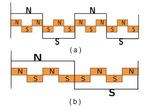 Figure 1: Pole pitch changes as per the procedure in Table 1
3. MIM PPM design
A nine phase induction motor which made by pole phase modulation concept as a full pitch, single-layer winding. In table 2, the slot numbers of both rotor and stator are chosen carefully to prevent none desired effects [9], [10]. More likely, crawling, cogging and cups synchronizing are none desired circumstances in machine functionality. The proposed design is depicted in figure 2.
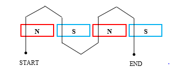 Figure 2: Two slots, four poles IM design (a single-phase connection sample)
The design is made to preserve one slot for each pole in each phase i.e. Q=1. Figure 3 demonstrates the pole-phase feasible combination of pole-phase modulation of nine phase motor along with excitation of each phase and polarity of the conductor. Arrows in figure 3 illustrate the conduction direction (polarity) inside the slot. Experiments showed that changing the number of phase angle of slots more likely for 40-degree phase angle of nine phases will yield a speed of 1500 rpm to the four poles combination. On the other hand, same four poles combined with nine phases of 120-degree will yield 500 rpm speed. Figure 3 demonstrates three-pole phase combinations of the machine; however, third part of the figure illustrates an alternative way of multiphase motor designing using a lesser number of inverter legs. However, this kind of design is having no roles in torque improvement or efficiency enhancement as well as speed control. In multiphase inverter speed control, inverter legs number (number of transistors in the inverter) need not change for performing speed control. Usually, angles of transistor firing which are generated using pulse width modulation are changed for fixing the pole pitch. Table 2 shows a parameters details with inverter integration of nine phases single layer induction motor.
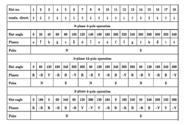 Figure 3: Chart of driver phase/slots distribution
Table 2: Nine phases single layer induction motor parameters details with inverter integration
| Particle | Details |
| Type of windings | Full pitch, one layer |
| Slots in stator | 36 |
| Slots in rotor | 49 |
| Rated power | 5 hp |
| Fill factor of slot | 63% |
| Length of core (cm) | 2.15 |
| Diameter of air gap (cm) | 1.70 |
| Air gap length (cm) | 35 e-4 |
| Number of IBGT | 8 |
| Number of DC inputs | 2 |
| Triggering method | PPW |
4. Inverter design
The five-level multilevel inverter is obtained by cascading three full-bridge inverter circuits. The three full-bridge inverters are connected in series and a single-phase output is taken. Each full-bridge is fed from a separate DC source. The number of output levels m in each phase is related to the number of full-bridge inverter units n by, m/2n+1. Here number of levels is five, hence number of inverter circuits connected in series is two. Where figure 4 shows general demonstration of PWM signals and reference signals. The single-phase five-level topology of cascaded H bridge multilevel inverter is shown in Figure 5. Each H-bridge is fed with the same value of DC voltage hence it can be called a symmetrical cascaded multilevel inverter. Each full-bridge inverter can generate three different voltage outputs: +Vdc, 0, and -Vdc. The output voltage is synthesized by the sum of two inverter outputs are at two angles. These two angles are used for giving pulses to eight switches.
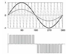 Figure 4: General demonstration of PWM signals and reference signals
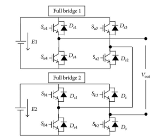 Figure 5: Circuit diagram of two levels DC-AC converter (inverter)
5. Design of high levels voltage generator
The observations made on four-pole, nine phases with two-level voltage exciters on each phase have shown the good performance of the induction machine. With nine phases, good performance is achieved while in the case of three phases-twelve poles, performance is noticeably reduced for the same level of phase voltage excitation. These observations are motivated thinking of another method to enhance the voltage through the phases (windings in each phase). The operations of three-phase twelve poles induction motors are similar to the same of nine phases and higher pole number induction motors. The equivalent voltage profile coins of twelve poles, three-phase induction motor are formulated by participation of four pole-nine phases windings (winding per phase) [10]. The real-life voltage profile coins are interconnected serially across each phase. The fact is changed while using a multilevel inverter, each voltage profile coin is supplied with voltage from an inverter leg. In another world, no actual voltage profile coins have existed unless the voltage is divided into several levels in each phase which gives the same impression of using a series winding as a voltage profile. So to say, the voltage effective during the phase is equal to the summation of each voltage across the voltage profile coin. This fact paved the way for increasing the voltage of each phase by providing more levels on member voltages without needing to device count increment, this might use the same control strategy of a standard phase setup before voltage levels uplifting. According to the chart in Figure 3, the effective phase voltage can be obtained as follows:
- For phase R, the voltage effective at the phase is a summation of voltages across phases a, d, and g. where the phase angle is zero.
- For phase Y, the voltage effective at the phase is a summation of voltages across phases b, e, and h. where the phase angle is 120 degree.
- For phase B, the voltage effective at the phase is a summation of voltages across phases c, f, and i. where the phase angle is 240 degree.
Each sub-phase i.e. (small lettered labeled phases such as a, b, g, etc.) represents a voltage profile coin and can be used to produce a voltage with multilevel by deploying techniques such as pulse width modulator. So-to-say, three phases displaced at a 60-degree phase difference can be used along with a pulse width modulator to generate a multilevel voltage. Those three voltages with 60-degree phases are known as reference voltages whereas the pulse width modulation signals are known as carrier signals. However, the output of the carrier and reference voltage combination will produce the waveform as in figure 4 shown above.
Multilevel inverter is basically working to convert a direct current voltage into an alternate current voltage by using multiple switching process. Figure 5 demonstrates the inverter prototype. Four switches are terms to four levels inverter. Switches are commonly made using a transistor such as IGBT, this type of transistor are performing switching operations by referring a firing signals generated from a pulse generator. Pulse width modulator is commonly used as pulse generator in multilevel inverter [11].
6. Outcomes
Performance of multilevel inverter combination with pole-phase modulation induction motor is investigated in three cases more likely: four pole-nine phase machines with two levels voltage (model 1), twelve pole-three phase machines with two levels voltage (model 2) and finally twelve pole-three phase machines with multilevel voltage (model 3). So figure 6 (a,b,c) shows comparison of torque performance and phase voltage obtained from each case by examination (model 1), (model 2), (model 3). The performance is studied in each case by examination of torque, torque ripple, torque ripple frequency, speed of the rotor, and power factor, As shown in the following figures (7,8,9,10,11) However, Table 3 demonstrates the performance according to the mentioned metrics.
Table 3: Results of the empirical models with different performance metrics
| Metric of performance | Model 1 | Model 2 | Model 3 |
| Output power | 3212 W | 3212 W | 3212 W |
| Torque ripple | 15 % | 31 % | 13 % |
| Frequency of torque level | 4.34 kHz | 1.89 kHz | 2.5 kHz |
| Speed | 1450 r.p.m | 470 r.p.m | 471 r.p.m |
| Power factor | 0.85 | 0.74 | 0.8 |
| Efficiency | 83 % | 63.2 % | 68 % |
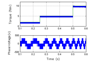 Figure 6 (a): Performance of torque and phase voltage (model 1)
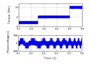 Figure 6 (b): Performance of torque and phase voltage (model 2)
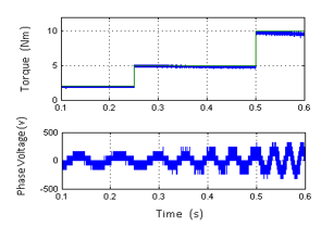 Figure 6 (c): Performance of torque and phase voltage (model 3)
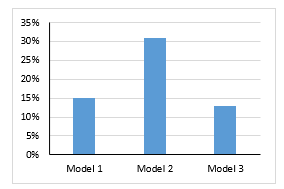 Figure 7: Torque ripple (fluctuation) during the experiments
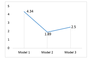 Figure 8: Ripple frequency (fluctuation) during the experiments
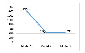 Figure 9: Speed control (fluctuation) during the experiments
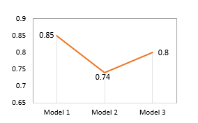 Figure 10: Power factor (fluctuation) during the experiments
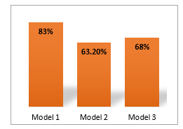 Figure 11: Efficiency (fluctuation) during the experiments
7. Conclusion
Induction motors are powerful drivers in large power industries which had significant importance in research sectors. This paper is illustrating an approach to enhance the efficiency of those machines by increasing the device count. Mainly, parameters such as voltage profile per phase and complexity of control strategy are interested to be examined. However, speed control is executed by changing the device count more specifically by changing the number of poles between different phase numbers. In this paper, three models are made namely: four pole-nine phase machines with two levels voltage (model 1), twelve pole three-phase machines with two levels voltage (model 2), and finally twelve pole three-phase machines with multilevel voltage (model 3). The performance of each model is tested using metrics such as efficiency, power factor, speed, torque ripple, and ripple frequency. Model 1 and model 2 are made using the conventional voltage profile enhancing method e.g. changing the device count in several iterations until reaching the required performance. However, this technique may face drawbacks like control complexity and device count increment which degrade the overall performance. Multilevel inverter is used to provide the required enhancement on the voltage profile and hence increase the efficiency and power factor on the machine without needing to increase the hardware complexity. Model 3 is outperformed over the other models as given in table 3.
- V.R. Nair, A.S. Rahul, R.S. Kaarthik, A. Kshirsagar, K. Gopakumar, “Generation of Higher Number of Voltage Levels by Stacking Inverters of Lower Multilevel Structures with Low Voltage Devices for Drives,” IEEE Transactions on Power Electronics, 32(1), 2017, doi:10.1109/TPEL.2016.2528286.
- E. Babaei, F. Sedaghati, “Series-parallel switched-capacitor based multilevel inverter,” in 2011 International Conference on Electrical Machines and Systems, ICEMS 2011, 2011, doi:10.1109/ICEMS.2011.6073330.
- D. Casadei, F. Profumo, G. Serra, A. Tani, “FOC and DTC: Two viable schemes for induction motors torque control,” IEEE Transactions on Power Electronics, 17(5), 2002, doi:10.1109/TPEL.2002.802183.
- G. Joksimovic, E. Levi, A. Kajevic, M. Mezzarobba, A. Tessarolo, “Optimal Selection of Rotor Bar Number for Minimizing Torque and Current Pulsations due to Rotor Slot Harmonics in Three-Phase Cage Induction Motors,” IEEE Access, 2020, doi:10.1109/ACCESS.2020.3045766.
- M.Z.R. Zuber Ahmadi, A. Jidin, K.B. Jaffar, M.N. Othman, R.N.P. Nagarajan, M.H. Jopri, “Minimization of torque ripple utilizing by 3-L CHMI in DTC,” in Proceedings of the 2013 IEEE 7th International Power Engineering and Optimization Conference, PEOCO 2013, 2013, doi:10.1109/PEOCO.2013.6564625.
- M.F. Escalante, J.C. Vannier, A. Arzandé, “Flying capacitor multilevel inverters and DTC motor drive applications,” IEEE Transactions on Industrial Electronics, 49(4), 2002, doi:10.1109/TIE.2002.801231.
- E. Levi, R. Bojoi, F. Profumo, H.A. Toliyat, S. Williamson, “Multiphase induction motor drives – A technology status review,” IET Electric Power Applications, 1(4), 2007, doi:10.1049/iet-epa:20060342.
- M. Mengoni, L. Zarri, A. Tani, L. Parsa, G. Serra, D. Casadei, “High-torque-density control of multiphase induction motor drives operating over a wide speed range,” IEEE Transactions on Industrial Electronics, 62(2), 2015, doi:10.1109/TIE.2014.2334662.
- B. Ge, D. Sun, W. Wu, F.Z. Peng, “Winding design, modeling, and control for pole-phase modulation induction motors,” IEEE Transactions on Magnetics, 49(2), 2013, doi:10.1109/TMAG.2012.2208652.
- B.S. Umesh, K. Sivakumar, “15 phase induction motor drive with 1:3:5 speed ratios using pole phase modulation,” in 2014 International Power Electronics Conference, IPEC-Hiroshima – ECCE Asia 2014, 2014, doi:10.1109/IPEC.2014.6869768.
- R. Sudharshan Kaarthik, K. Gopakumar, J. Mathew, T. Undeland, “Medium-voltage drive for induction machine with multilevel dodecagonal voltage space vectors with symmetric triangles,” IEEE Transactions on Industrial Electronics, 62(1), 2015, doi:10.1109/TIE.2014.2327576.