Comparative Study of Control Algorithms Through Different Converters to Improve the Performance of a Solar Panel

Adv. Sci. Technol. Eng. Syst. J. 6(2), 629–634 (2021);
 DOI: 10.25046/aj060272
This article aims at comparing two controls to follow the maximum power point, making use of DC-DC converters for PV uses. All transformers operate continuously. To fulfil maximum power, we will exploit two MPPT controls: a traditional perturb – observe ‘P&O’ and a smart one – the fuzzy logic ‘FL’. The goal of this article is two-fold: to scrutinize the efficiency of DC-DC transformers (Boost, Buck, Cuk and SEPIC), and to assess the outcomes of the simulation. For the construction of models and simulations, the Matlab / Simulink environjment is employed.
1. Introduction
There has been recently a crucial advancement in renewable energies. With its permanent potential and without adverse effect on the external environment, new energies are an adequate and affordable technique for development. The main lines of research concerning the conversion of new energies are as follows: recovery of basic energy, mechanical transformation, electrical transformation, electricity production, conversion, and injection into the network. The main axis is to determine the quality of “green” energy generation [1, 2].
Transformers DC-DC are an essential constituent in power generation. These converters are chiefly used in connection with batteries, wind turbines, hybrid systems, solar panel. Transformers DC-DC are to match the tension between the input stage and the output stage of a system. In this work we will make a comparison between different converters: Boost, Buck, Sepic and Cuk for two commands perturb – observe ‘P&O’ and fuzzy logic ‘FL’, in order to obtain the maximum power of a solar panel source for meteorological variations conditions [3, 4].
2. Modeling of Photovoltaic System
The fundamental element of the solar panel is the semiconductor, consisting of many cells mounted in shunt or mounted in cascade. The photovoltaic cell is schematized by a circuit: a parallel resistance, a series resistance, and a single diode, represented in figure 1 [5].
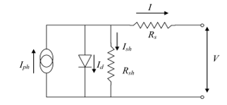 Figure 1: Circuit of solar panel cell.
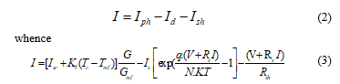
The relationship of the electrical intensity current Iph:
![]() whereby KI is the temperature coefficient [%/K]; Isc is the short intensity current [A]; Tc is the module temperature [K], G is the sunlight solar effect [W/m²]; Tref = 298 K and Gref = 1000 W/m². [6, 7]
whereby KI is the temperature coefficient [%/K]; Isc is the short intensity current [A]; Tc is the module temperature [K], G is the sunlight solar effect [W/m²]; Tref = 298 K and Gref = 1000 W/m². [6, 7]
The formula giving the electrical intensity I is:
 where
where
Iph the short electrical intensity,
Is the electrical intensity saturation of the diode;
q the elementary charge of the electron (1.60.10-19 C);
V the diode tension (V);
K the Boltzmann’s universal constant (1.38.10-23 J/K);
T the temperature,
N Ideality factor of the diode,
Rs the cascade resistance,
Rsh is the parallel resistance,
3. Prepare Transformers DC-DC analysis
The transformers DC-DC is a very important element in power generation of a solar panel. It is a block between the load and the photovoltaic panel that allows to extract the maximum power for the panel.
The transformers DC-DC consists of a capacitor, a diode, an inductor, commanded switch (controlled by PWM signal) and uncontrolled switch.
3.1. Buk Transformer
The buck transformer makes it possible to reduce the input tension [8].
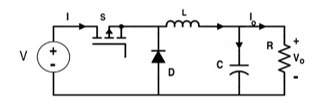 Figure 2: Buck transformer.
The relationship between input tension and output tension is:
![]() where D represents the duty cycle.
where D represents the duty cycle.
3.2. Boost transformer
The boost transformer allows to increase the input tension [9, 10].
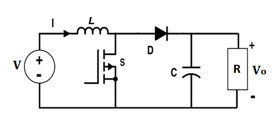 Figure 3: Boost transformer.
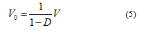
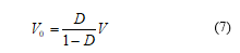
The relationship between input tension and output tension is:
 3.3. Cuk transformer
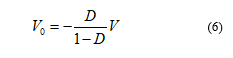
Cuk transformer converts the input tension into a tension of the opposite sign. [11, 12].
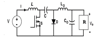 Figure 4: Cuk transformer.
The relationship between input tension and output tension is:
 3.4. SEPIC transformer
The SEPIC transformer is drawn from of the Cuk which gives a positive output tension [13].
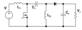 Figure 5: Sepic transformer
The relationship between input tension and output tension is:
 4. MPPT techniques
The aim of the maximum power point tracking technique is to determine the maximum power operating point by changing the duty – cycle ratio of the DC-DC transformer, and then moving to the relevant point.
In this article two MPPT techniques are used: Perturb – Observe and fuzzy – logic ‘FL’.
4.1. Technique P and O
The perturb and observe P&O command is ranked among the most used techniques. As its name suggests, this technique involves disturbing the VPV voltage of a low amplitude around its initial value, and examining the impact on the power at the output of the Solar panel.
Figure 6 shows the structure of the Perturb – Observe command [14,15].
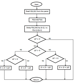 Figure 6: Organization chart P&O
4.2 Fuzzy – Logic ‘F-L’
The ‘F-L’ technique is used in a point tracking system maximum MPPT power, this technique offers the importance of being a powerful technique and relatively simple to develop and it does not require exact specification of the model to be regulated. The ‘F-L’ technique is more suitable for non-linear systems than photovoltaic systems. The process of this technique is executed in three blocks: Fuzzification, defuzzification and inference. This figure supplies the clue 7 [16].
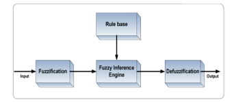 Figure 7: ‘F-L’ diagram
The ‘F-L’ diagram input parameters are: the variation of the error CE and the error E giving by the formula:
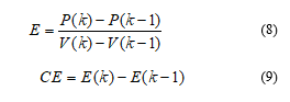
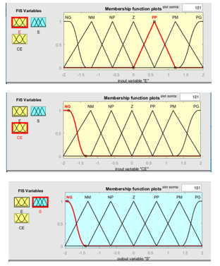 Figure 8: Output and inputs parameter
Table I below shows the different combination inference rules that link the linguistic parameters E (Error), CE (Variation of error) and output S (Output Variable).
Table 1: ‘F- L’ INFERENCE
| E CE | NG | NM | NP | Z | PP | PM | PG |
| NG | NG | NG | NG | NM | NM | NP | Z |
| NM | NG | NG | NM | NP | NP | Z | PP |
| NP | NG | NM | NM | NP | Z | PP | PM |
| Z | NM | Z | NP | Z | PP | PM | PM |
| PP | NM | NP | Z | PP | PM | PM | PG |
| PM | NP | Z | PP | PM | PM | PG | PG |
| PG | Z | PP | PM | PM | PG | PG | PG |
5. Simulation and Results
Under Matlab Simulink environment the PV system is modeled. In this block we find mainly: the equivalent diagram of the converter, the command used and a PV system predefined in Matlab simulink.
 Figure 9: Diagram Block of the Perturb—Observe and fuzzy—Logic commands for the different transformers processed
Figure 9 presents an overview of all blocks: photovoltaic panel, DC-DC converter, MPPT commands, irradiation data et temperature data.
The Solar panel used in the simulations is P20-36-TDC-36-20W.
Table 2: P20-TDC-36-20W
| No-Load tension (V) | 21,20 |
| Tension at maximum power (V) | 17,20 |
| Short-intensity current (A) | 1,280 |
| Current at maximum power (A) | 1,170 |
| Puissance maximum (W) | 20,0 |
| The Coefficient of temperature of (%/deg.C) | 0.360990 |
| Coefficient of temperature of (%/deg.C) | 0.0650 |
Figures 10 and 11 depicts the change of the real solar radiation the and temperature data over a day.
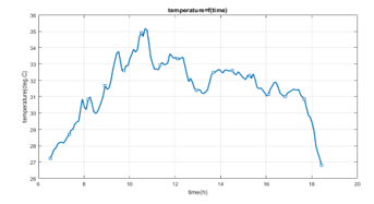 Figure 10: The change of temperature
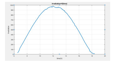 Figure 11: The change of solar radiation
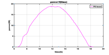 Figure 12: Power with Perturb-observe technique for the Boost transformer
Figures 12,13,14 and 15 enumerates the outcomes of the different transformers: Boost, Buck, CUK and SEPIC, using as a technique the Perturb and Observe.
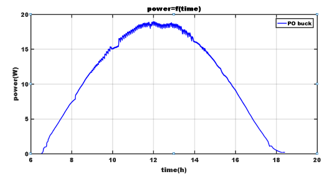 Figure 13: Power with Perturb-observe technique for the Buk transformer
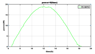 Figure 14: Power with Perturb-observe technique for the Sepic transformer
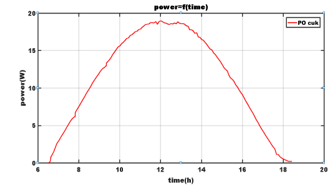 Figure 15: Power with Perturb-observe technique for the Cuk transformer
For the second simulation figures 16,17,18 and 19 the fuzzy logic command was used.
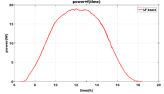 Figure 16: Power with ‘F-L’ technique for the Boost transformer
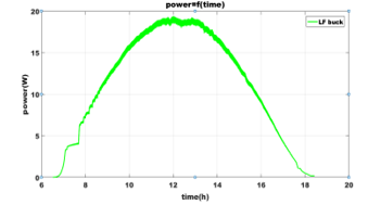 Figure 17: Power with ‘F-L’ technique for the Buck transformer
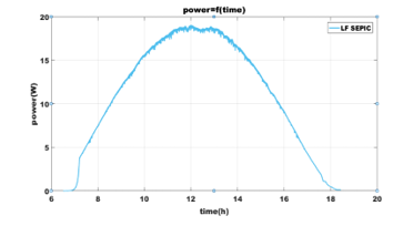 Figure 18: Power with ‘F-L’ technique for the Sepic transformer
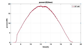 Figure 19: Power with ‘F-L’ technique for the for the Cuk transformer
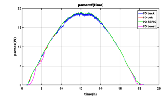 Figure 20: Evolution of power for the four transformer with Perturb-Observe
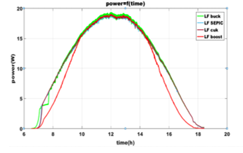 Figure 21: Evolution of power for the four transformer with ‘F-L’
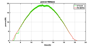 Figure 22: The best power produced with Perturb-Observe and fuzzy-logic
In the Perturb-Observe technique simulation context, the power of photovoltaic panel in the Sepic transformer – is maximal with regard to other transformers, but it is more stable in the boost transformer.
In the ‘F-L’ technique, the power photovoltaic panel in the Buck transformer generate more power compared to other transformers; it is also more stable, but in Boost transformer context.
6. Conclusion
This article studied two maximum power point tracking techniques – a traditional Perturb-Observe and a smart one: ‘F-L’ control to obtain the maximum power of the panel photovoltaic.
In this work, four DC-DC transformers are used to improve the quality of the MPP tracking by analyzing the power produced and the stability of each converter.
Simulation results gives an overview of the power evolution for a temperature and solar effect irradiation data for a day.
- S. Zouirech, M. Zerouali, A. El Ougli, B. Tidhaf, “The Impact of the Type of Converter and the Algorithm of the Control on the Production of Maximum Power by a Photovoltaic System, ” 7th International Renewable and Sustainable Energy Conference (IRSEC). IEEE, 1-5, 2019, doi:10.1109/IRSEC48032.2019.9078204.
- M. Zerouali, S. Zouirech, A. El Ougli, B. Tidhaf, H. Zrouri, “Improvement of Conventional MPPT Techniques P&O and INC by Integration of Fuzzy Logic, ” 7th International Renewable and Sustainable Energy Conference (IRSEC). IEEE, 1-6, 2019, doi:10.1109/IRSEC48032.2019.9078330.
- S. Saravanan, N.R. Babu, “Maximum power point tracking algorithms for photovoltaic system,” Renewable and Sustainable Energy Reviews, 57, 192-204, 2016, doi:10.1016/j.rser.2015.12.105.
- J.P. Ram, T.S. Babu, N. Rajasekar, “A comprehensive review on solar PV maximum power point tracking techniques,”. Renewable and Sustainable Energy Reviews, 67, 826-847, 2017, doi:10.1016/j.rser.2016.09.076
- S. Miqoi, A. El Ougli, B. Tidhaf, A.Rabhi, “Application of fuzzy logic on a PV water pumpingsystem,” 3rd International Symposium Environmental Friendly Energies and Applications (EFEA), St. Ouen, 1-6, 2014, doi: 10.1109/EFEA.2014.7059961.
- T. Arunkumari, V. Indragandhi, S. Sreejith, “Topologies of a DC–DC Converter for Micro-grid Application and Implementation of Parallel Quadratic Boost Converter,”. Advances in Smart Grid and Renewable Energy, Springer, Singapore, 633-644, 2018, doi:10.1007/978-981-10-4286-7_63.
- S. Zouirech, M. Zerouali, H. Elaissaoui, A. El Ougli, B. Tidhaf, “Application of Various Classical and Intelligent MPPT Tracking Techniques for the Production of Energy through a Photovoltaic System, ” 7th International Renewable and Sustainable Energy Conference (IRSEC). IEEE, 1-6, 2019, doi:10.1109/IRSEC48032.2019.9078154.
- A.P.K. Yadav, S. Thirumaliah, G.Haritha, “Comparison of mppt algorithms for dc-dc converters based pv systems,” International Journal of Advanced Research in Electrical, Electronics and Instrumentation Engineering, 1(1), 18-23, 2012., ISSN: 2278– 8875.
- S. Nemsi, L. Barazane, S. Diaf, A. Malek, “Comparative study between two maximum power point tracking (MPPT) techniques for photovoltaic system,” Journal of renewable energies, 16 (4), 773-782, 2013, ISSN: 1112-2242 .
- M. Boutouba, A. El Ougli, S.Miqoi, B.Tidhaf, “Design and Experimentation of a Control System Implemented on Raspberry Pi 3 Board for Photovoltaic Systems Using SEPIC Converter,” Journal of Electrical Systems, 13(4), 661-677, 2017, ISSN 1112-5209.
- J. Chauhan, P. Chauhan, T. Maniar, A. Joshi, “Comparison of MPPT algorithms for DC-DC converters based photovoltaic systems,”. International Conference on Energy Efficient Technologies for Sustainability IEEE, 476-481, 2013, doi: 10.1109/ICEETS.2013.6533431.
- R. Patii, H. Anantwar, “Comparitive analysis of fuzzy based MPPT for buck and boost converter topologies for PV application,” International Conference On Smart Technologies for Smart Nation (SmartTechCon), Bangalore, 1479-1484, 2017, doi: 10.1109/SmartTechCon.2017.8358610.
- L. Jotham Jeremy, C.A. Ooi, J. Teh, “Non-isolated conventional DC-DC converter comparison for a photovoltaic system: A review,” Journal of Renewable and Sustainable Energy, 12(1), 013502, 2020, doi:10.1063/1.5095811.
- M.M. Algazar, H. Al-Monier, H.A. El-Halim, M.E.E.K. Salem, “Maximum power point tracking using fuzzy logic control,” International Journal of Electrical Power & Energy Systems, 39(1), 21-28, 2012, doi:10.1016/j.ijepes.2011.12.006.
- D. Verma, S. Nema, A.M. Shandilya, S.K. Dash,”Maximum power point tracking (MPPT) techniques: Recapitulation in solar photovoltaic systems,”. Renewable and Sustainable Energy Reviews, 54, 1018-1034, 2016, doi:10.1016/j.rser.2015.10.068.
- S. Vinu, V. Anoop, P. Dixit, A. Arjaria; U. Chourasia; P. Bhambri; R. MR, R. Sundararaj, “CCGPA-MPPT: Cauchy preferential crossover based global pollination algorithm for MPPT in photovoltaic system,” Progress in Photovoltaics: Research and Applications, 28(11), 1128-1145, 2020, doi:10.1002/pip.3315.