Neural Networks and Fuzzy Logic Based Maximum Power Point Tracking Control for Wind Energy Conversion System

Adv. Sci. Technol. Eng. Syst. J. 6(2), 586–592 (2021);
 DOI: 10.25046/aj060267
In grid connected wind turbine (WT) systems, the maximum power point tracking (MPPT) approach has a crucial role in optimizing the wind energy efficiency. To search for the maximum power value of the wind turbine, this contribution proposes a new Maximum Power Point Tracking System (MPPT) for wind turbine related to a permanent magnet synchronous generator (PMSG)). The new proposed MPPT combines two techniques: Artificial Neural Network (ANN) and Fuzzy Logic (FL). The ANN is employed to estimate the maximum voltage of the WT, for various values of wind speed, while the control of DC–DC boost converter operation is executed by applying Fuzzy Logic technique. The comparison of our proposed algorithm to P&O technique has shown that it ensures more efficiency, and we used for that a simulation under Matlab/Simulink.
1. Introduction
Nowadays, motivated by the environmental issues caused by the outrageous use of traditional energy resources such as oil, natural gas or coal, many countries in the world tend to an ecological transition. They also pay more attention to the ecological effects generated by this ruinous exploitation such as: global warming, air pollution, etc.
Due to their adaptability and ease of use, renewable energies are currently a crucial form of energy used in different fields. Thus, we are going to concentrate in this contribution on the case of wind turbine as a mechanism of generating renewable energy.
Wind turbine is an unflagging source of renewable energy that is able to produce electricity, using the power of the wind. It is also worth to mention that the wind power plants can be established either on earth or in oceans. [1]
The WT is an instrument that converts the dynamic wind energy into electrical energy, which will be sent to the power grid. In the grid connected systems of wind turbines (WT), the maximum power point tracking algorithm (MPPT) is a pivotal criteria to improve the wind energy productivity.
In last few years, diverse MPPT techniques have been applied, the major controllers that are used extensively are Climb Search (HCS) or Power Signal Feedback (PSF), Perturbation and Observation (P&O), Optimal Torque Control (OTC), Top Speed Ratio (TSR) and methods of soft computing such as Fuzzy Logic Control (FLC) and Artificial Neural Network (ANN).
The Perturb and observe (P&O) or HCS (Hill climb search) control methods are applied when the system’s optimal relation is determined. The P&O approach is used to follow the MPP, by changing the maximization factor and measuring the obtained power.
The MPPT controller based on the Fuzzy Logic Controller (FLC) and the (ANN) are designed to overcoming the limitation of all methods listed above. They have a more rapid response, in the case of fast varying wind speeds.
This article exhibits a new approach for Maximum Power Point Tracking for Wind Energy Conversion System.
In fact, we propose a new MPPT based mainly on fuzzy logic (FL) and Artificial Neural Networks (ANN) and by doing so we will be able to take out maximum power of the wind turbine. The idea is to use the ANN to estimate the maximum voltage of the WT using different values of wind speed, while a fuzzy controller will be responsible of controlling the DC-DC boost converter.
Our system involves wind turbine related to a permanent magnet synchronous generator (PMSG), a rectifier and a DC-DC converter with MPPT control.
Our results have shown that the proposed system guarantee more efficiency in terms of tracking the MPPT and extracting the maximum power of a WT.
The proposed model is presented in figure 1 below:
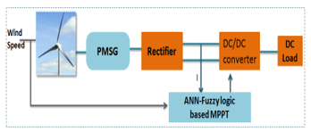 Figure 1: Overall schematic of PMSG based ANN and Fuzzy logic
The manuscript is structured as listed below:
Section 2 describes the designing of a WT wind turbine. The section 3 presents the modeling of the used converter. Section 4 explains the different types of MPPT controllers used in this article: ANN and FLC and later P&O. Section 5 gives the results obtained from the simulation realized in this work with a discussion of the performances of the proposed algorithm.
2. Modeling of A WT
The mathematical expression of the mechanical power generated by the WT is presented by the following equation presents: [2]
![]() Par is the output mechanical power of the turbine (w), ρ is the air density (kg/ m3), Cp (λ, β) is the performance coefficient of the turbine, , A is the turbine swept area (m2) , is the wind speed (m/s), λ is the tip speed ratio, and β is the blade pitch angle (deg).
Par is the output mechanical power of the turbine (w), ρ is the air density (kg/ m3), Cp (λ, β) is the performance coefficient of the turbine, , A is the turbine swept area (m2) , is the wind speed (m/s), λ is the tip speed ratio, and β is the blade pitch angle (deg).
![]() R means the turbine ratio (m), ω is the turbine angular velocity (rad/s).
R means the turbine ratio (m), ω is the turbine angular velocity (rad/s).
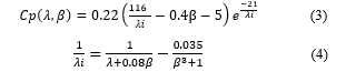
The power coefficient is in accordance with β and λ. The coefficient of performance is shown as below:
 The aerodynamic torque is presented as follows:
![]() Based on equation 1, we can say that the most significant factor to achieve the maximum power produced by a wind turbine is the curve of Cp; in fact, When the Cp is at maximum, it means that the power produced by the wind turbine has reached its maximum. For this work, β is equal to zero.
Based on equation 1, we can say that the most significant factor to achieve the maximum power produced by a wind turbine is the curve of Cp; in fact, When the Cp is at maximum, it means that the power produced by the wind turbine has reached its maximum. For this work, β is equal to zero.
Every different value of λ we obtain a constant β and an optimum Cp. For every wind speed value, we can define a unique rotor speed that allows achieving a maximal power. Thereby, considering the wind speed constant invariable, the optimum Cp value will be bound only on the wind turbine rotor speed [3].
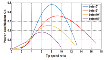 Figure 2: Characteristics of power coefficient
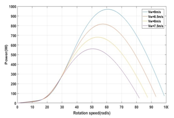 Figure 3: Power graphs under various wind speeds (β=0)
The parameters of the Turbine Generator are detailed as follows:
Table 1: WT generator system characteristics
| Characteristics | Values |
| Rated Voltage | 90 V |
| Rated Power | 1000W |
| Synchronous inductance | 1mH |
| Rated Current | 4.8A |
| Number of poles | 8 |
| Synchronous resistance | 1.13Ω |
| Friction coefficient | 0.006N.m.s/rad |
| Magnetic flux | 0.16Wb |
| Moment of inertia | 0.005N.m |
| Blade length | 1.2m |
| Air density | 1.2 kg/ m3 |
3. Converter Modelling
The boost converter is basically a voltage step-up power converter which accepts a low-voltage input and delivers an output at a much higher voltage. The DC/DC boost converter topology is the most commonly used topology. [4]
The electrical circuit of DC/DC boost converter used in this contribution is shown in the figure below:
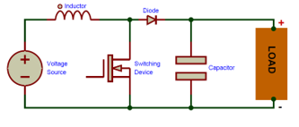 Figure 4: Configuration of Boost converter
The Boost Converter is the conventional basic DC/DC converter, which runs with a single switch.
The boost converter contains a capacitor, a switch, a diode for its operation, and an inductor, as illustrated in Figure 4. [5]
Once the switch is activated, the diode is reverse-biased, the current begins to increase by charging the inductor; and a capacitor holds the charge.
The model of the boost converter is as described below:
![]() The Vo, V are the output and the input voltage respectively.
The Vo, V are the output and the input voltage respectively.
The mathematical expression of the parallel chopper is:
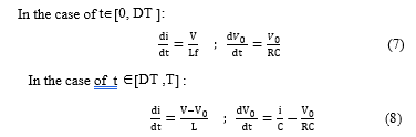 The inductor of the boost converter and capacitor are determined by:
![]()
![]() where and f are the approximate inductor ripple current and the corresponding switching frequency, respectively. Δ the estimated output ripples voltage.
where and f are the approximate inductor ripple current and the corresponding switching frequency, respectively. Δ the estimated output ripples voltage.
4. The proposed MPPT method for the Wind Turbine
To search the maximum power produced by the wind turbine, we propose a new power tracking approach based mainly on fuzzy logic (FL) and Artificial Neural Network (ANN), as shown in Figure 5.
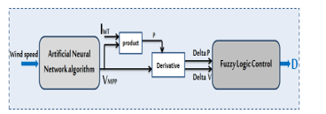 Figure 5: Block diagram developed MPPT
In this paper, two steps are applied to keep track the PPM of the WT.
In the first step, the ANN is used to obtain an Estimated Optimal Voltage Value (VMPP) for each wind speed value.
ANN estimates the maximum value of voltage of the wind turbine associated to each given wind speed. It predicts the value of VMPP based on the training of a database that combines each wind speed with the associated Vout voltage.
During the second step, the Fuzzy Logic method is implemented to give the value of the Duty cycle.
From the maximum voltage (VMPP) and the value of the current IWT, the derivatives deltaP and deltaV are calculated, which will then be the Fuzzy block inputs. The fuzzy logic controller is implemented to indicate the value of Duty cycle based on the inputs delta P (power) and delta V (voltage).
4.1. ANN Based MPPT Algorithm
The design of artificial neural networks is based on the biological neuron structure of the human brain. Artificial neural networks can be described as systems composed of at least two layers of neurons, an input layer and an output layer and usually including hidden layers. If the problem is complex, the artificial neural network must have more layers. Each layer contains a large number of specialized artificial neurons.[6]
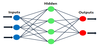 Figure 6: ANN Diagram
Neurons are linked and interchange with each other. Every neuron node has data as an increment and it is able to execute trivial operations on it.
Afterward, the outcome of these actions is delivered to other neurons. The result of each neuron node is called the nodes activation or node value.
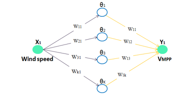 Figure 7: VMPP prediction using ANN
where 1 represents the wind speed value, it is the input of the ANN, 1 represents the output VMPP (optimal voltage).
The artificial neural network is created from a program under Matlab, based on the training of a given database (wind speed, V).
In our case, in the first layer, the optimized number of neurons is forty neurons, the second layer has one purelin neuron, one neuron in the input layer and also one in the output layer is constructed. The model of network is as below:
 Figure 8: Neural Network Model
4.2. FLC For Wind Turbine
The strong point of the fuzzy logic controller is that it deals with the unspecific inputs and nonlinearity and brisk changes.
FLC is mainly The FLC is mainly structured in three phases that represent the fuzzification, the fuzzy inference engine (rule base table determined by previous instructions) and defuzzification.
Fuzzification: Transform numeric input values to linguistic values using a membership function. [7]
Rules base: Fuzzy rules have been used to characterize the connection that exists between the output and input of the fuzzy control. The number of fuzzy rules depends, among other things, on the partition of the speech universes of the input and output parameters. [8]
Defuzzification: This step consists of converting a linguistic value into a numerical value.
In this method, the fuzzy logic controller is used to indicate the value of D based on the inputs delta P (power) and delta V (voltage).
The process of FLC for the WT subsystem is shown in Figure 10.
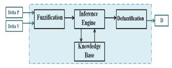 Figure 9: Structure of a fuzzy controller
DeltaP and DeltaV are shown by the equations below:
DeltaP (k) =P(k)-P(k -1) (11)
DeltaV (k) =V(k)-V(k -1) (12)
The membership functions of DeltaP, DeltaV and D are respectively shown in Figure 10(a), Figure 10(b) and Figure 10 (c).
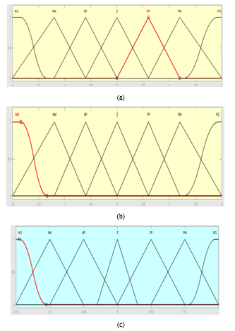 Figure 10: Membership functions related to (a) DeltaP, (b) DeltaV, (c) D.
The table 2 shows the inference rules for the various combinations of the variables DeltaP, DeltaV with output D. [9]
Table 2: Inference Rules related to Fuzzy Logic WT
| Delta V
Delta P |
NG | NM | NP | Z | PP | PM | PG |
| NG | NG | NG | NG | NM | NM | NP | Z |
| NM | NG | NG | NM | NM | NP | Z | PP |
| NP | NG | NM | NM | NP | Z | PP | PM |
| Z | NM | Z | NP | Z | PP | PM | PM |
| PP | NM | NP | Z | PP | PM | PM | PG |
| PM | NP | Z | PP | PM | PM | PG | PG |
| PG | Z | PP | PM | PM | PG | PG | PG |
4.3. Perturb and Observe Based MPPT Algorithm for wind turbine
The Perturb and observe (P&O) method is the most widely employed because of its simple implementation. The concept of this algorithm is illustrated in Figure 11.
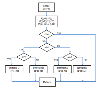 Figure 11. Perturb and Observe Approach (P&O)
5. Results and Discussion
The proposed algorithm is verified with MATLAB SIMULINK, as illustrated in Figure 12:
To implement the new MPPT algorithm and to verify its efficiency, MATLAB / SIMULINK is used as shown in Figure 12.
The system includes the following elements: a wind turbine, a permanent magnet synchronous generator (PMSG), a rectifier, a boost converter, an ANN block and a fuzzy logic block.
Figure 13 shows that the wind speed varied in three stages, it passes from 8.4 m / s to 8.5m / s, then to 9.1 m / s.
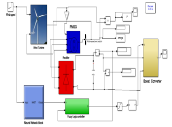 Figure 12: ANN-Fyzzy based MPPT algorithm deployment on Simulink
 Figure 13: Varying wind speed
Figure 14 shows, the variation of the performance coefficient, for the wind speed which varies between 8.4m/s, 8.5m/s, and 9.1m/s.
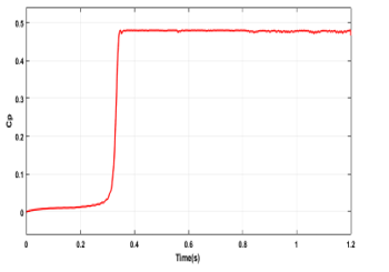 Figure 14: power coefficient for different wind speed.(maximum value is 0.48) using ANN-Fuzzy algorithm
Our results seem to confirm that our system is able to keep track of its MPP (Cp=0.48) considering various wind speed values.
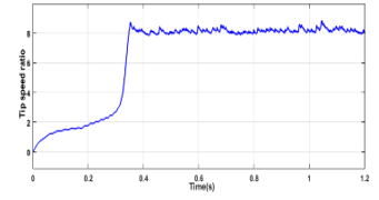 Figure 15: Tip speed ratio curve under a varying wind speed using ANN-Fuzzy logic algorithm
According to the simulation results the power coefficient and tip speed ratio are set at the maximum values.
Figure 16 shows the torque evolution curve related to the proposed approach based on ANN and Fuzzy logic.
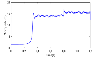 Figure 16: Mechanical torque curve under a varying wind speed using ANN-Fuzzy algorithm
Figure 17 shows the WT’s mechanical output power, using the new ANN-FL MPPT approach, for the wind speed which varies between 8.4m/s, 8.5m/s, and 9.1m/s.
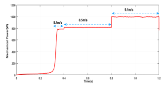 Figure 17: The output mechanical power under different wind speed using ANN-Fuzzy algorithm
By comparing the evolution of the power delivered by WT (figure17), with the results of figure3, under different wind speeds, we can deduce that our system is able to keep track of the maximum mechanical power through new MPPT method based on ANN and Fuzzy logic.
Figure 18 shows the WT’s mechanical output power, using the P&O algorithm, for wind speed which varies between 8.4m/s, 8.5m/s, and 9.1m/s.
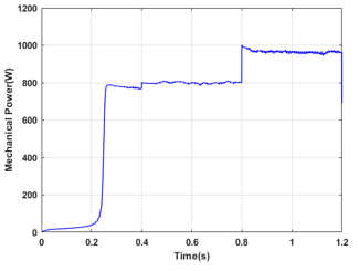 Figure 18: The output mechanical power under different wind speed using P&O algorithm
By comparing the evolution of the power delivered by WT (figure18), with the results of figure3, under different wind speeds, we can deduce that the system can’t reach the maximum mechanical power through MPPT based on P&O.
By comparing the power curves provided by WT using the ANN and Fuzzy Logic algorithm and the one using P&O, it seems that the ANN technique reaches the maximum power with more stability than the P&O technique.
The P&O technique is not able to achieve MPP, because the power delivered using P&O is not maximum and it represents a significant oscillation, as shown in the power curve.
6. Conclusion
As a way to improving the power produced by the wind turbine it is necessary to track and extract the maximum power point.
This work presents a new MPPT method based on the ANN and fuzzy logic method. The idea is to combine these two methods, to provide an efficient system that outstrip the P&O based one in terms of MPPT and extracting maximum power from the WT. In the proposed approach, the ANN estimates the value of VMPP for various wind speed values while Fuzzy logic controller gives the value of Duty cycle D for controlling the DC-DC boost converter.
In order to show the efficiency of the proposed new approach based on ANN and fuzzy logic, it has been compared with the famous P&O algorithm.
The simulation realized in this work demonstrates that the maximum power point tracking based on the ANN and FLC algorithm can track and maintain the maximum power delivered by the wind energy production for every wind speed value. According to these results, it is undeniable that the new MPPT based on ANN and fuzzy logic is more efficient than the P&O method.
Based on the results of the simulation, it appears that the validity of the proposed MPPT controller has been confirmed for wind speed variations, using MATLAB /SIMIULINK.
- A. Choumane, O. Boukhari, “Wind energy in Algeria: potential and achievements,” in International conference on renewable energy strategies and its role in achieving sustainable development.
- M. Zerouali, M. Boutouba, A. El Ougli and B. Tidhaf, “ Control of variable speed wind energy conversion systems by fuzzy logic and conventional P&O,” in 2019 International Conference on Intelligent Systems and Advanced Computing Sciences (ISACS), 1-5, IEEE, 2019, doi: 10.1109/ISACS48493.2019.9068866.
- P. Suresh, B.C. Sujatha, “Maximum Power Point Tracking Of A Hybrid Solar-Wind Power Generation System For A Smart Grid Using Fuzzy Logic Control,” International Journal of Scientific & Engineering Research, 7(5), 165-170, 2016.
- S.S. Dheeban, N.B. Muthu Selvan, C. Senthil Kumar, “Design Of Standalone Pv System,” International Journal Of Scientific & Technology Research, 8(11), 2019.
- I. Duka, C. Noble. “ High frequency DC/DC boost converter,” submitted to the Faculty of the Worcester Polytechnic Institute in partial fulfillment of the requirements for the Degree of Bachelor of Science in Electrical and Computer Engineering , 2011.
- J.K. Gowri, M.C. Popuri, “Neutral Networks Based Maximum Power Point Tracking (Mppt) Of Wind Power Generation,” in The International Journal of Scientific Development and Research (IJSDR), 5(2), 2020.
- K.H. Lee, “First course on fuzzy theory and applications,” in Springer Science & Business Media, 2004.
- C.C. Lee, “Fuzzy logic in control systems: fuzzy logic controller. I,” IEEE Transactions on systems, man, and cybernetics, 20(2), 404-418, 1990, doi: 10.1109/21.52551.
- H. Othmani, H. Chaouali, D. Mezghani, A. Mami. ” Optimisation de la Technique de Perturbation et Observation par la logique floue,” International Journal of Scientific Research & Engineering Technology (IJSET), 2015.