Complex Order PI\(^{a+jb}\)D\(^{c+jd}\) Controller Design for a Fractional Order DC Motor System

Adv. Sci. Technol. Eng. Syst. J. 6(2), 541–551 (2021);
 DOI: 10.25046/aj060261
Industry 4.0 implementation stipulates effective actuator control. In the present work, a complex order PIa+jb Dc+jd (COPID) controller was designed for a fractional order model of a direct current (DC) motor system. For comparisons, the DC motor system model was also controlled using the conventional proportional integral (PI), proportional integral derivative (PID), proportional resonant (PR) and fractional order PID controllers (FOPID). Time domain results indicated that the PR controller performed exceedingly well for output signal responses, but fared poorly in case of control signal specifications. The PI controller responses suffered from high time domain characteristics for both control and output signals. The PID controller performed moderately in terms of time domain and peak overshoot metrics. The FOPID controller attained the best time domain characteristics but was unable to effectively limit the control and output signal peak overshoots. It was only the COPID controller, that successfully minimised/eliminated peak overshoots in control and output signals (0.1 % and 0.0 % respectively). Moreover, the COPID controller was also successful in limiting the rise, peak and settling times. In addition, Bode diagram, root locus plot were obtained and system gain parameters were varied to confirm the robustness of the proposed COPID controller. Thus, COPID controller promises to be an effective solution towards accurate and robust actuator control in modern manufacturing.
1. Introduction
This paper is an extension of the paper presented at the IEEE International Conference on Mechatronics, Robotics and Systems Engineering, MoRSE 2019 [1]. Therein, a direct current (DC) motor system was successfully modeled by the application of fractional calculus to closed loop system identification approach. Of the four identified fractional order models, the best performing model comprised of three parameters and attained R-squared 0.9942, root mean square error (RMSE) 0.0084 and sum of squared estimate of errors (SSE) 0.0711. In the current work, that fractional order model has been utilised to implement PI, PR, PID, fractional order PID (FOPID) and complex order PIa+jbDc+jd (COPID) controller designs with an aim to achieve stable and robust control of the DC motor system with minimum time domain characteristics.
The proportional, integral and derivative (PID) controllers have been implemented in industrial control systems on a large scale owing to their simplicity of design and maintenance [2]. Recently, fractional calculus has been employed to solve various complex problems in engineering and science [3]–[7]. One of these applications is designing controllers using fractional calculus. The fractional order controllers have been shown to exhibit superior control characteristics in numerous applications including the nonminimum phase systems [8]–[12]. This is due to the additional two parameters available for control in the fractional model structure. The complex order PIa+jbDc+jd controller is a logical extension of the fractional calculus based control as it includes two more parameters for control as compared to the FOPID controller [13]–[16].
In [17], the authors implemented a complex order structure to identify hexapod robot movement on the basis of a transfer function for the foot-ground system. In [18], the authors obtained a transfer function to solve a complex order differential equation. In [19], the author employed genetic algorithm to optimize complex order controllers for non linear and linear systems. In [20], the authors investigated robust control of a non linear fuel cell system using complex order architecture. In [21], the authors modeled HIV infection drug resistance using a complex order model. In [16], the authors reviewed time domain, stability and frequency domain in complex order modeling of various systems. In [22], the authors tuned complex order controller by numerical optimization for a time delay resonant plant. In [23], the authors tuned complex order controller using genetic algorithm. In [13], the authors compared complex controller performances to integral and fractional order controllers for fractional order systems. They reported superior time domain characteristics attained by the complex order controllers. However, they did not apply complex order controllers to a DC motor system. A complex order controller was designed for DC motors [24]. However, the designed controller in this work [24] was unable to minimise the overshoot in the step response. minimizing peak overshoot in the output signal response is critical to prevent any undesired process variation which may damage the actuated machinery in the long run. Similarly, minimizing control signal overshoots is critical to prevent damage against voltage spikes and enhance the service life of DC motors in industry [25, 26].
The main contribution of the current work lies in the identification of the most suitable DC motor controller design based on minimal output/control signal peak overshoots and settling times among the various controllers considered in the scope of the current study. The following section (2) details upon the controller design methodology adopted in the current work pertaining to the PI, PID, PR, FOPID and COPID controllers. Time and frequency domain results of the investigated controllers are compared and discussed in section 3. Finally, conclusions of the present work are presented in the section 4.
2. Controller Design Methodology
The current work addresses the constant torque region for DC motor modeling and control. The field weakening region (figure 1 ) is not considered in the present work.
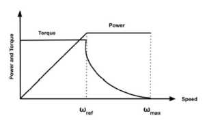
Figure 1: Field weakening region [27]
Following sub-sections describe the PI, PID, PR, COPID and FOPID controllers for the DC motor system considered in the current study.
2.1 PI and PID controller
The PID controller is popular in industry because of its compatibility with the PLCs and its simple structure[2, 28]. The following PID controller structure was used for the DC motor system [29].
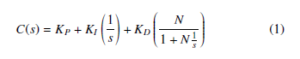
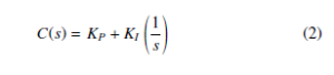
where, N is the bandwidth of the low pass filter on the derivative, KP is proportional gain, KI is integral gain and KD is derivative gain. This controller was tuned by the auto tuning capability available in the Matlab Simulink block. Auto-tuning can be done via time and frequency based methods. In this work, frequency based auto tuning method was implemented. In the case of PI controller, KD is zero and there is no need of derivative filter. It’s structure is given as follows. !
2.2 PR Controller
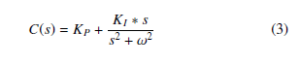
The PI controller yields infinite gain at s = 0 and generally responds in a slow mode to step inputs without any steady state error. Moreover, it is unable to trace sinusoidal reference input. The PR controller yields infinite gain at zero phase shift and resonant frequency. Its form is given as follows [30]–[32].
2.3 FOPID controller
FOPID controllers are based on fractional calculus wherein the orders of derivation and integration are real numbers [9, 33]. Fractional calculus has been defined in many ways. The following definitions are generally applied in control system applications [34].
2.3.1 Grunwald-Letnikov definition
The GL (Grunwald-Letnikov) definition is very effective for obtaining numerical solutions of the fractional differential equations [35]. This definition is expressed as follows
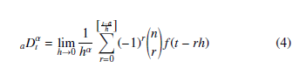
where, the integer part is represented by [t−ha]; t and a are the limits of operator; n is an integer subjected to n − 1 < α < n. The binomial coefficient is expanded as follows !
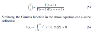
2.3.2 Riemann-Liouville definition
The Riemann-Liouville definition is appropriate for the determination of analytical solutions of simple functions like et,tb,cos(t) [36]. Riemann and Liouville applied fractional operators to derive formulae for the integration of arbitrary numbers and for solving differential equations respectively. The Riemaann-Liouville definition combines the distinct approaches followed by Riemann and Liouville in a composite formula expressed as follows –
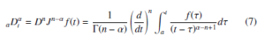
where, J is the integral operator, α is a real number, n is an integer subjected to n − 1 < α < n and t , a are the limits of integration.
For example, if α is 1.8, n will be two because 1 < 1.8 < 2.
2.3.3 M. Caputo definition
The M. Caputo definition is very popular among engineers because it directly relates the type of fractional derivative to the corresponding type of initial conditions [37]. In this definition, initial conditions like y(0) and y0(0) are allowed; unlike y0.5(0) (fractional conditions)
[8]. The Caputo definition of fractional calculus is given as follows
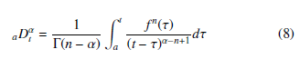
where, α is a real number, n is an integer subjected to n − 1 <
α < n and t, a are the limits of integration. As stated before, fractional calculus is a branch of mathematics wherein the orders of integration and derivation are real numbers [9, 33, 38]. This real number feature has a significant impact towards improvement of the controller performance [39]–[41]. The classical PID Controllers are particular cases of fractional controllers where λ and µ are equal to one (figure 2). With reference to the PID plane, this implies that instead of moving between four fixed points it is possible for λ and µ to move across the entire plane [42].
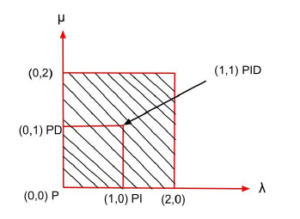
Figure 2: FOPID region in λ – µ plane [9]
The fractional PID controller structure implemented in the current work (figure 3) is given as follows.
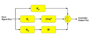
Figure 3: Fractional PID controller structure [43]
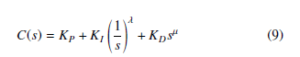
where λ is the order of integration and µ is the order of derivative. In FOPID, there are two more parameters in the controller structure as compared to PID controller. Because of this, two more specifications can be achieved using the FOPID controller. The parameter range of orders is generally accepted 0 to 2 for the stability of the closed loop system because the locations of closed-loop poles lie mostly in the first sheet of Riemann [44] in this order range. The same approach has been followed in the current study as well. The fractional differentiator can be synthesised for FOPID controller application using Oustaloup’s recursive approximation method as follows –
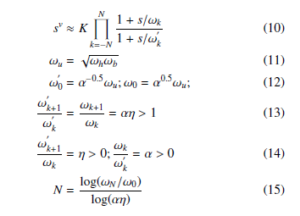
where ωh, ωb are the approximation frequency bounds, v is the order of the fractional differentiator, N is the order of fractional differentiator approximation and K is a constant. In the present work, the fractional order controller was implemented using FOMCON toolbox for fractional calculus [45, 46]. In this toolbox, fractional calculus can be approximated using the refined Oustaloup approximation method by varying the order and frequency ranges. This toolbox can be used for time domain, frequency domain and many more analyses for fractional calculus. The fractional order parameters in the current study were tuned based on the approach given in related literature [39].
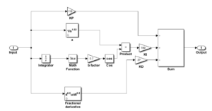
Figure 4: Complex PIa+jbDc+jd controller structure
2.4 COPID controller
Just as the FOPID controller is an extension of the classical PID controller, similarly the COPID controller is an extension of the FOPID controller. In complex order PID controller, integration and derivative orders are expressed in the form of a complex number (x+jy). The genesis of COPID controller is related to the CRONE controller (third generation) [47, 48]. The complex order PID controller structure for the DC motor fractional order model in the current study is given as follows [14, 20, 49].
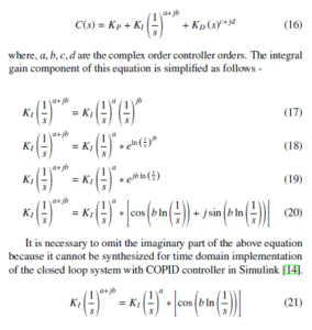
Similarly, the derivative part of Eq. (16) is simplified as follows –
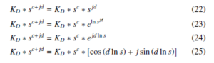
As followed in case of the integral gain component, it is necessary to omit the imaginary part of the derivative equation as well because it cannot be synthesized for time domain implementation of the closed loop system with COPID controller in Simulink [14].
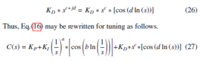
The tuning of complex order controller is more challenging than FOPID and classical PID controller as there are seven parameters in the complex order controller. In this work, Eq. (27) was utilised for the implementation of complex order controller. This controller was tuned based on the tuning principles provided in literature [39, 50]. Figure 4 shows the structure of the COPID controller implemented in Simulink (Matlab). The initial value of the integer order integration was assumed to be a small number for this implementation. For all controllers, high control signal overshoots were limited by adding saturation block in the closed loop system models.
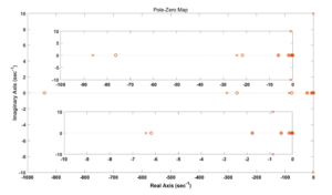
Figure 5: Pole zero map for fractional order DC motor plant model
3. Results and Discussions
The fractional order DC motor system model derived in the work reported in the 2019 IEEE International Conference on Mechatronics, Robotics and Systems Engineering (MoRSE) [1] is given below.
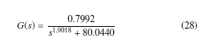
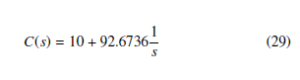
It may be noted that this model has a low DC gain. Low DC gains in second / higher integer order system models are expected to cause the system responses to become sluggish due to the presence of the non-dominant pole(s) in the pole zero map. Similar effect is observed in the pole zero map (figure 5) of the fractional order system model considered in the current study as well. However, the presence of a large number of dominant poles keep the system response fast; overcoming the adverse impact of low DC gain. This model consisting three parameters was employed for designing the PI, PR, PID, FOPID and COPID controllers in the current work. The PI controller design for the DC motor system was obtained as follows –
Figures 6 and 7 show the output and control signal plots for the PI controller respectively.
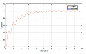
Figure 6: PI controller output for fractional order DC motor plant model
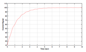
Figure 7: Control signal for PI controller output for fractional order DC motor plant model
Similarly, the following PR controller structure for the DC motor system was generated –
The output and control signal responses for the PR controller are depicted in figures 8 and 9 .
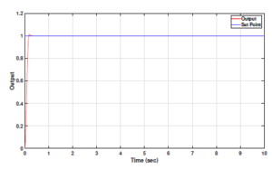
Figure 8: PR controller output for fractional order DC motor plant model
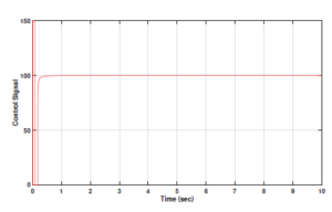
Figure 9: Control signal for PR controller output for fractional order DC motor plant model
The auto tuned PID controller architecture for the fractional order DC motor plant model considered in the current study was obtained as follows –
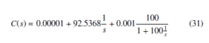
Figure 10 shows the output response of the PID controller output, whereas figure 11 shows the control signal plot for the same.
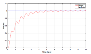
Figure 10: PID controller output for fractional order DC motor plant model
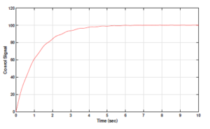
Figure 11: Control signal for PID controller output for fractional order DC motor plant model
The fractional order PID controller structure was obtained as follows –
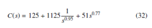
Figures 12 and 13 depict the output and control signal responses for this FOPID controller, respectively.
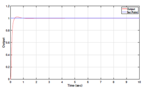
Figure 12: Fractional PID controller output for fractional order DC motor plant model
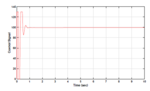
Figure 13: Control signal for Fractional PID controller output for fractional order DC motor plant model
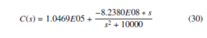
The complex order PID controller structure was obtained as follows –
![]()
Figures 14 and 15 show the output response and the control signal of the complex controller designed for the DC motor system.
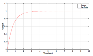
Figure 14: Complex PIa+jbDc+jd controller output for fractional order DC motor plant model
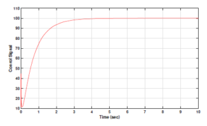
Figure 15: Control signal for complex PIa+jbDc+jd controller output for fractional order DC motor plant model
Table 1 gives the output signal rise and peak time domain specifications of all controllers explored for the DC motor system considered in the current study. The PR controller is successful in attaining the least rise time and peak time among all controllers. The FOPID controller attains the second best peak and rise time characteristics. The COPID controller registers higher rise and peak times as compared to FOPID output signals. The PI and PID controller output signals consume relatively higher rise and peak times. Figures 16 and 17 showcase graphical presentations of output signal overshoots and settling times.
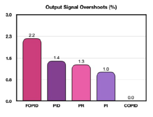
Figure 16: Output signal overshoots (%)
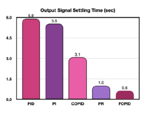
Figure 17: Output signal settling time (sec)
Table 1: Time domain specifications of output signals
|
||||||||||||||||||||||||||||||||||||||||
The FOPID controller achieves the least settling time, whereas the COPID controller minimizes peak overshoot percentage to zero. In contrast, the PR, PI, PID and FOPID output signals record overshoots of 1.3 %, 1.0 %, 1.4 % and 2.2 % respectively. This result proves the efficacy of the complex order controller in limiting the output signal overshoot for the DC motor system. The DC motor system output is the output shaft revolutions per minute. In industrial systems, DC motor outputs actuate machinery for achieving the stipulated processing control. Eliminating peak overshoots in the DC motor output signals is important to avoid undesirable process variations which may be detrimental and even hazardous in some cases.
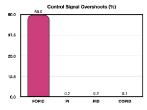
Figure 18: Control signal overshoots (%)
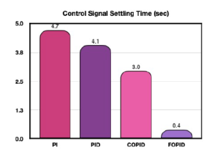
Figure 19: Control signal settling time (sec)
Table 2 shows the control signal time domain characteristics for the five controllers under the scope of the current study. In this case, the PR controller performed very poorly and registered extremely high overshoot (of the order of 10E6); rise, peak and settling times. The FOPID control signals attained minimum rise and peak times, followed by COPID and PID control signals. The PI control signals achieved much higher rise and peak time metrics. Figures 18 and 19 showcase graphical presentations of control signal overshoots and settling times. The PI controller also under performed with respect to the settling time metric. However, it performed much better in case of control signal peak overshoots. Similarly, the PID controller attained very low peak overshoot but suffered from higher settling time. The FOPID controller attained minimum settling time, but was unable to keep the control signal overshoot in check. Thus, it was only the COPID which consistently outperformed all other controllers with minimum peak overshoot and second best settling time characteristics. For DC motor systems, the control signal corresponds to the voltage input. Excessive voltage spikes (as evident in FOPID control signal response) may prove detrimental to the motor’s active service life and might even result in premature damage. It is important for the controller design to ensure protection to the DC motor against high voltage shocks. Moreover, faster settling of the input voltage corresponding to the desired output set point is desirable for a highly responsive system. The COPID controller exhibited reliable performances in both aspects.
Figures 20 and 21 show the Bode plot and root locus diagram for the closed loop system with COPID controller. The Bode plot indicates that the gain and phase margin for the closed loop system with COPID controller is ∞. This implies that the system is robust against variations in the system parameters. Similarly, the location of closed loop poles to the left side of the s-plane in root locus diagram also proves that the DC motor system performance is stable and robust under complex order controller. Figure 22 depicts the robustness of the COPID controller against variations in the gain of the DC motor system. The system gain was varied with values of 0.5, 0.8, 2, 5, 10 and 20. The gain variations do not have any significant impact on the settling trends of the COPID controller responses, which is a positive indication.
4. Conclusions
The current work is an extension of the one reported in the 2019 IEEE International Conference on Mechatronics, Robotics and Systems Engineering (MoRSE). Building upon the fractional order model of the DC motor system identified in the previous work; the current work involved design of PI, PR, PID, FOPID and COPID controllers for the same. Primary results indicate that the PR controller performed very well in output signal responses; but fared very poorly in control signal time specifications. The PI controller also performed poorly in terms of output and control signal rise, peak and settling times. However, it performed comparatively better in terms of peak output and control signal overshoots. The PID controller’s performance was mediocre in terms of control and output signal peak, rise and settling times. Its performance was also not very impressive with regards to the output signal peak overshoots, but it did much better in minimizing the control signal overshoot percentage. The FOPID controller attained very low rise, peak and settling times for its output signals. However, it suffered from the highest peak overshoots for both output and control signal responses. The COPID controller exhibited excellent performance with regards to minimizing / eliminating the peak overshoots in the control (0.1 %) and output signal (0.0 %) responses. COPID controller also attained the second best low range rise, peak and settling time values. Minimisation and possible elimination of the peak overshoots in the control and output signals is vital for ensuring the safety of the controlled process machinery as well as for the long service life of the DC motor based industrial actuators. The COPID controller fulfills this requirement without sacrificing the settling time much. In addition, the Bode plot, root locus diagram and stable controller responses under varying system gain parameter confirm the stability and robustness of the designed complex order controller for the fractional order DC motor plant model considered in the current study. Thus, complex order controllers can be extensively and safely applied towards industry 4.0 oriented implementation of advanced industrial control systems such as smart actuators and collaborative robots.
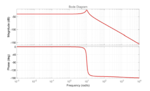
Figure 20: Bode plot for complex order controller for fractional order DC motor plant model
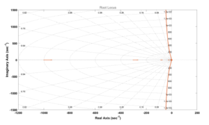
Figure 21: Root locus for complex order controller for fractional order DC motor plant model
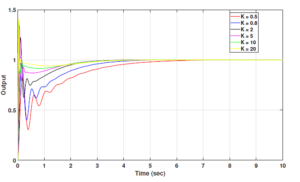
Figure 22: Responses of complex order controller for various values of K
- P. Shah, R. Sekhar, “Closed Loop System Identification of a DC Motor us- ing Fractional Order Model,” in 2019 International Conference on Mecha- tronics, Robotics and Systems Engineering (MoRSE), 69–74, IEEE, 2019, doi:https://doi.org/10.1109/morse48060.2019.8998744.
- K. J. Åstro¨m, P. Eykhoff, “System identification—a survey,” Automatica, 7(2), 123–162, 1971, doi:https://doi.org/10.1016/0005-1098(71)90059-8.
- R. Sekhar, T. Singh, P. Shah, “ARX/ARMAX Modeling and Fractional Or- der Control of Surface Roughness in Turning Nano-Composites,” in 2019 International Conference on Mechatronics, Robotics and Systems Engineer- ing (MoRSE), 97–102, IEEE, 2019, doi:https://doi.org/10.1109/MoRSE48060. 2019.8998654.
- W. Zheng, Y. Luo, Y. Chen, Y. Pi, “Fractional-order modeling of permanent magnet synchronous motor speed servo system,” Journal of Vibration and Control, 1–26, 2015, doi:https://doi.org/10.1177/1077546315586504.
- P. Shah, S. Agashe, A. P. Singh, “Fractional order modelling using state space theory,” International Journal of Engineering and Technology, 5(3), 2891–2894, 2013, doi:http://www.enggjournals.com/ijet/docs/IJET13-05-03-343.pdf.
- R. Bhimte, K. Bhole, P. Shah, “Fractional Order Fuzzy PID Controller for a Rotary Servo System,” in 2018 2nd International Conference on Trends in Electronics and Informatics (ICOEI), 538–542, IEEE, 2018, doi:https://doi.org/10.1109/ICOEI.2018.8553867.
- R. Bhimte, K. Bhole-Ingale, P. Shah, R. Sekhar, “Precise Position Control of Quanser Servomotor using Fractional Order Fuzzy PID Controller,” in 2020 IEEE Bombay Section Signature Conference (IBSSC), 58–63, IEEE, 2020, doi:https://doi.org/10.1109/IBSSC51096.2020.9332216.
- I. Podlubny, “Fractional-order systems and fractional-order controllers,” In- stitute of Experimental Physics, Slovak Academy of Sciences, Kosice, 12(3), 1–18, 1994, doi:http://people.tuke.sk/igor.podlubny/pspdf/uef0394.pdf.
- P. Shah, S. Agashe, “Review of fractional PID controller,” Mechatronics, 38, 29–41, 2016, doi:https://doi.org/10.1016/j.mechatronics.2016.06.005.
- M. Zamani, M. Karimi-Ghartemani, N. Sadati, M. Parniani, “Design of a fractional order PID controller for an AVR using particle swarm opti- mization,” Control Engineering Practice, 17(12), 1380–1387, 2009, doi: https://doi.org/10.1016/j.conengprac.2009.07.005.
- P. Shah, R. Sekhar, S. Agashe, “Application of Fractional PID Controller to Single and Multi-Variable Non-Minimum Phase Systems,” International Journal of Recent Technology and Engineering, 8(2), 2801–2811, 2019, doi: https://doi.org/10.35940/ijrte.b2805.078219.
- C. A. Monje, Y. Chen, B. M. Vinagre, D. Xue, V. Feliu-Batlle, Fractional- order systems and controls: fundamentals and applications, Springer Science & Business Media, 2010, doi:https://doi.org/10.1007/978-1-84996-335-0.
- A. V. Tare, J. A. Jacob, V. A. Vyawahare, V. N. Pande, “Design of novel optimal complex-order controllers for systems with fractional-order dynam- ics,” International Journal of Dynamics and Control, 7(1), 355–367, 2019, doi:https://doi.org/10.1007/s40435-018-0448-5.
- M. Shahiri, A. Ranjbar, M. R. Karami, R. Ghaderi, “New tuning design schemes of fractional complex-order PI controller,” Nonlinear Dynamics, 84(3), 1813– 1835, 2016, doi:https://doi.org/10.1007/s11071-016-2608-5.
- B. Ross, W. Haven, F. H. Northover, “A use for a derivative of complex order in the fractional calculus,” 1978, doi:https://insa.nic.in/writereaddata/ UpLoadedFiles/IJPAM/20005a85 400.pdf.
- J. A. Jacob, A. V. Tare, V. A. Vyawahare, V. N. Pande, “A review of time domain, frequency domain and stability analysis of linear complex- order systems,” in 2016 IEEE International WIE Conference on Electrical and Computer Engineering (WIECON-ECE), 164–169, IEEE, 2016, doi: https://doi.org/10.1109 8009110.
- M. F. Silva, J. T. Machado, R. S. Barbosa, “Complex-order dynamics in hexapod locomotion,” Signal processing, 86(10), 2785–2793, 2006, doi: https://doi.org/10.1016/j.sigpro.2006.02.024.
- J. L. Adams, T. T. Hartley, L. I. Adams, “A solution to the fundamental linear complex-order differential equation,” Advances in Engineering Software, 41(1), 70–74, 2010, doi:https://doi.org/10.1016/j.advengsoft.2008.12.014.
- J. T. Machado, “Optimal controllers with complex order derivatives,” Jour- nal of Optimization Theory and Applications, 156(1), 2–12, 2013, doi: https://doi.org/10.1007/s10957-012-0169-4.
- M. Shahiri, A. Ranjbar, M. R. Karami, R. Ghaderi, “Robust control of non- linear PEMFC against uncertainty using fractional complex order control,” Nonlinear Dynamics, 80(4), 1785–1800, 2015, doi:https://doi.org/10.1007/ s11071-014-1718-1.
- C. M. Pinto, A. R. Carvalho, “Effect of drug-resistance in a fractional complex- order model for HIV infection,” IFAC-PapersOnLine, 48(1), 188–189, 2015, doi:https://doi.org/10.1016/j.ifacol.2015.05.162.
- A. Guefrachi, S. Najar, M. Amairi, M. Aoun, “Tuning of fractional complex order PID controller,” IFAC-PapersOnLine, 50(1), 14563–14568, 2017, doi: https://doi.org/10.1016/j.ifacol.2017.08.2093.
- O. Hanif, G. B. Babu, S. Sharma, “Performance Improvement of PIx+iy D Frac- tional Complex Order Controller using Genetic Algorithm,” in 2018 Fourth International Conference on Advances in Electrical, Electronics, Informa- tion, Communication and Bio-Informatics (AEEICB), 1–5, IEEE, 2018, doi: https://doi.org/10.1109/AEEICB.2018.8480981.
- K. Khandani, A. A. Jalali, M. R. R. Mehdiabadi, “Robust complex order controller design for DC motors,” in 20th Iranian Conference on Electrical Engineering (ICEE2012), 900–903, IEEE, 2012, doi:https://doi.org/10.1109/ IranianCEE.2012.6292481.
- A. Ma’arif, N. R. Setiawan, “Control of DC Motor Using Integral State Feedback and Comparison with PID: Simulation and Arduino Implemen- tation,” Journal of Robotics and Control (JRC), 2(5), 456–461, 2021, doi: https://doi.org/10.18196/jrc.25122.
- M. Khalifa, A. H. Amhedb, M. Al Sharqawi, “Position Control of Real Time DC Motor Using LabVIEW,” Journal of Robotics and Control (JRC), 2(5), 342–348, 2021, doi:https://doi.org/10.18196/jrc.25104.
- P.-Y. Lin, Y.-S. Lai, “Novel voltage trajectory control for field-weakening oper- ation of induction motor drives,” IEEE Transactions on Industry Applications, 47(1), 122–127, 2010, doi:https://doi.org/10.1109/TIA.2010.2091092.
- D. Somwanshi, M. Bundele, G. Kumar, G. Parashar, “Comparison of fuzzy-PID and PID controller for speed control of DC motor using LabVIEW,” Procedia Computer Science, 152, 252–260, 2019, doi:https://doi.org/10.1016/j.procs. 2019.05.019.
- C. Sa´nchez-Lo´pez, V. Carbajal-Go´mez, M. Carrasco-Aguilar, F. Morales- Lo´pez, “PID controller design based on memductor,” AEU-International Journal of Electronics and Communications, 101, 9–14, 2019, doi:https: //doi.org/10.1016/j.aeue.2019.01.019.
- N. Zhang, H. Tang, C. Yao, “A systematic method for designing a PR controller and active damping of the LCL filter for single-phase grid-connected PV invert- ers,” Energies, 7(6), 3934–3954, 2014, doi:https://doi.org/10.3390/en7063934.
- J. Zhang, L. Li, D. G. Dorrell, Y. Guo, “Modified PI controller with improved steady-state performance and comparison with PR controller on direct matrix converters,” Chinese Journal of Electrical Engineering, 5(1), 53–66, 2019, doi:https://doi.org/10.23919/CJEE.2019.000006.
- J. Gnanavadivel, R. Thangasankaran, N. S. Kumar, K. Krishnaveni, M. Schlenk, “Performance Analysis of PI Controller and PR Controller Based Three- Phase AC-DC Boost Converter with Space Vector PWM,” International Journal of Pure and Applied Mathematics, 118(24), 1–16, 2018, doi:https://acadpubl.eu/hub/2018-118-24/3/501.pdf.
- E.-H. Dulf, “Simplified fractional order controller design algorithm,” Mathe- matics, 7(12), 1166, 2019, doi:https://doi.org/10.3390/math7121166.
- K. Oldham, J. Spanier, The fractional calculus : theory and applications of differentiation and integration to arbitrary order, 1st Edition, Elsevier, 1974, doi:https://cutt.ly/RznbhbX.
- I. Petras, “Tuning and implementation methods for fractional-order con- trollers,” Fractional Calculus and Applied Analysis, 15(2), 282–303, 2012, doi:https://doi.org/10.2478/s13540-012-0021-4.
- A. Loverro, “Fractional calculus: history, definitions and applications for the engineer,” Rapport technique, Univeristy of Notre Dame: Department of Aerospace and Mechanical Engineering, 2004, doi:https://www.academia.edu/ download/36579354/FracCalc.pdf.
- D. Cafagna, “Fractional calculus: A mathematical tool from the past for present engineers,” IEEE Industrial Electronics Magazine, 2(1), 35–40, 2007, doi:https://doi.org/10.1109/MIE.2007.901479.
- R. Sekhar, T. Singh, P. Shah, “Micro and Nano Particle Composite Machining: Fractional Order Control of Surface Roughness,” in Third International Con- ference on Powder, Granule and Bulk Solids: Innovations and Applications, 35–42, 2020, doi:https://cutt.ly/LzvarrI.
- P. Shah, S. Agashe, “Experimental Analysis of Fractional PID Controller Parameters on Time Domain Specifications,” Progress in Fractional Differenti- ation and Applications, 3, 141–154, 2017, doi:http://dx.doi.org/10.18576/pfda/ 030205.
- P. Shah, S. Agashe, A. J. Kulkarni, “Design of a fractional PIλDμ controller using the cohort intelligence method,” Frontiers of Information Technology & Electronic Engineering, 19(3), 437–445, 2018, doi:https://doi.org/10.1631/ FITEE.1601495.
- S. Nangrani, S. Bhat, “Fractional order controller for controlling power sys- tem dynamic behavior,” Asian Journal of Control, 20(1), 403–414, 2018, doi:https://doi.org/10.1002/asjc.1557.
- S. E. Hamamci, “An algorithm for stabilization of fractional-order time delay systems using fractional-order PID controllers,” Automatic Control, IEEE Transactions on, 52(10), 1964–1969, 2007, doi:https://doi.org/10.1109/TAC. 2007.906243.
- R. Gupta, S. Gairola, “FOPID controller optimization employing PSO and TRSBF function,” in 2015 2nd International Conference on Recent Advances in Engineering & Computational Sciences (RAECS), 1–6, IEEE, 2015, doi: https://doi.org/10.1109/RAECS.2015.7453275.
- P. Shah, S. Agashe, V. Vyawahare, “System identification with fractional-order models: A comparative study with different model structures,” Prog. Fract. Diff. Appl., 4(4), 533–552, 2019, doi:https://doi.org/10.18576/pfda/040407.
- A. Tepljakov, FOMCON: Fractional-Order Modeling and Control Tool- box, 107–129, Springer International Publishing, Cham, 2017, doi:10.1007/ 978-3-319-52950-9 6.
- A. Tepljakov, E. Petlenkov, J. Belikov, I. Petra ́s, “FOMCON toolbox for modeling, design and implementation of fractional-order control systems,” Ap- plications in Control; Petra´s, I., Ed.; De Gruyter: Berlin, Germany, 211–236, 2019, doi:https://doi.org/10.1515/9783110571745-010.
- P. Lanusse, A. Oustaloup, B. Mathieu, “Third generation CRONE control,” in Proceedings of IEEE Systems Man and Cybernetics Conference-SMC, volume 2, 149–155, IEEE, 1993, doi:https://doi.org/10.1109/ICSMC.1993. 384864.
- S. Das, Functional fractional calculus, Springer Science & Business Media, 2011, doi:https://doi.org/10.1007/978-3-642-20545-3.
- M. Zheng, G. Zhang, T. Huang, “Tuning of fractional complex-order direct cur- rent motor controller using frequency domain analysis,” Mathematical Methods in the Applied Sciences, 2020, doi:https://doi.org/10.1002/mma.6653.
- K. H. Ang, G. Chong, Y. Li, “PID control system analysis, design, and technol- ogy,” IEEE transactions on control systems technology, 13(4), 559–576, 2005, doi:https://doi.org/10.1109 7331.