
A Novel Approach for Evaluating Eddy Current Loss in Wind Turbine Generator Step-Up Transformers
Volume 6, Issue 2, Page No 488-498, 2021
Author’s Name: Bonginkosi Allen Thangoa), Jacobus Andries Jordaan, Agha Francis Nnachi
View Affiliations
Department of Electrical Engineering, Tshwane University of Technology, Emalahleni, 1034, South Africa
a)Author to whom correspondence should be addressed. E-mail: thangotech@gmail.com
Adv. Sci. Technol. Eng. Syst. J. 6(2), 488-498 (2021); ![]() DOI: 10.25046/aj060256
DOI: 10.25046/aj060256
Keywords: Wind energy, Transformer, Eddy currents, Harmonics, Temperature rise

Export Citations
South Africa is aiming to achieve a generation capacity of about 11.4GW through wind energy systems, which will contribute nearly 15.1% of the country’s energy mix by 2030. Wind energy is one of the principal renewable energy determinations by the South African government, owing to affluent heavy winds in vast and remote coastal areas. In the design of newfangled Wind Turbine Generator Step-Up (WTGSU) transformers, all feasible measures are now being made to drive the optimal use of active components with the purpose to raise frugality and to lighten the weight of these transformers. This undertaking is allied with numerous challenges and one of them, which is particularly theoretical, is delineated by the Eddy currents. Many times the transformer manufacturer and also the buyer will be inclined to come to terms with some shortcomings triggered by Eddy currents. Still and all, it is critical to understand where Eddy currents emanate and the amount of losses and wherefore the temperature rise that may be produced in various active part components of WTGSU transformers. This is the most ideal choice to inhibit potential failure of WTGSU transformers arising from excessive heating especially under distorted harmonic load conditions. In the current work, an extension of the author’s previous work, new analytical formulae for the Eddy loss computation in WTGSU transformer winding conductors have been explicitly derived, with appropriate contemplation of the fundamental and harmonic load current. These formulae allow the distribution of the skin effect and computation of the winding Eddy losses as a result of individual harmonics in the winding conductors. These results can be utilized to enhance the design of WTGSU transformers and consequently minimize the generation of hotspots in metallic structures
Received: 25 December 2020, Accepted: 03 February 2021, Published Online: 17 March 2021
1. Introduction
South Africa remains engaged in diversifying the power mix that will make it possible to reduce the subjection to coal power generation. The ongoing decommissioning of various coal power plants resulting from end of service life, can potentially make way for a radically distinct power mix as opposed to the current monopolization by coal power plants which have an installed capacity of 40GW [1]. At the present day, South Africa’s Department of Energy through the Renewable Energy Independent Power Producer’s Procurement Programme (REI4P) has deployed a total of 64 renewable energy facilities, of which 25 are wind energy constituting of 961 wind turbines with a total generation capacity of 2,1 GW [2]. Wind energy currently contributes 52% of the country’s renewable energy capacity [3]. The wind energy tariff is currently at about R0.62/kWh, in which is about 45% less than the tariff for a coal plant. Each turbine generator in a wind energy facility is furnished with a step-up transformer at the bottom of the tower as shown in Figure 1 (a), which transforms its output voltage to a desired medium voltage (MV) collector level. In South Africa, these Wind Turbine Generator Step-Up (WTGSU) transformers are failing at an unnerving rate and utility owners are confound to ascertain the potential causes for these prevailing deficiencies. A typical WTGSU transformer failure arising from an insulation failure which is attributable to a disc-to-disc short circuit failure to generate a spark that ignites the transformer oil as shown in Figure 1 (b).
Field experience is indicating that these failures are triggered by the use of regular distribution (RD) transformers that cannot meet the required operational requirements of the wind energy environment. With the objective to pledge future dependability of wind energy in South Africa, WTGSU transformers must integrate these requirements particularly with regard to a deformed loading cycle, harmonics and distortion, de-rating, switching over-voltages and stray gassing.
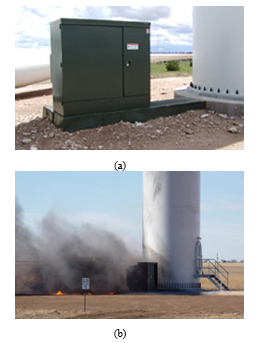 Figure 1: (a) WTGSU transformer during service; (b) Ignition of a WTGSU transformer.
Nonlinear loads and sporadic wind turbine generators are infamous for producing harmonic load currents and call for WTGSU transformers to connect them safely to the electrical network [4-5]. Transformers are commonly designed under the presumption of sinusoidal loading conditions [6-7]. It is widely known that distorted harmonic load currents accentuates the service losses in transformer and ultimately the temperature rise and generation of hotspots in metallic structures, resulting in degradation of insulation materials and untimely failures as shown in Figure 1 (b) [8-10].
Transformer windings are conceivably the most crucial part of WTGSU transformers, electrically and mechanically, and they are one of the major contribution of untimely failures in WTGSU transformers [11]. The contribution of winding conductors to WTGSU transformer failures is about 80%, which is a significant portion among the failures caused by other transformer parts [11]. In view of the increasing proclivity of nonlinear loads in the power system, the WTGSU transformers are more notably susceptible to fail. As a result, to minimize power losses and excessive heating in winding conductors, magnetic shielding [12-13], and laminating the core material [14-15] has been proposed in the literature.
At tender stage, it is essential to evaluate the transformer winding stray losses triggered by the EMFs. In this way, the inception of new formulae is recommendable and endeavor to enhance the computation and evaluation methods. A number of studies have been undertaken recently which take these objectives into account [16-20]. Thus, analytical techniques have demonstrated to be efficacious in computing the electromagnetic service losses. In a broader sense, there are two commonly used techniques in the transformer manufacturing industry to evaluate the winding Eddy current losses: (i) direct computation of the EMF using Maxwell’s equations in [21-22] and (ii) use of Poynting’s theorem in [21-22]. Early attempts to compute the EMF using both these methods are presented by authors in [23]. In the book Transformer Engineering: Design and Practice [24], the authors described these methods and how they can be embedded into manufacturers internal design programs to compute the Eddy currents. Design programs based on the Finite element Method to compute the Eddy currents are witnessed in the publications [25-28].
Owing to the increasing renewable energy market and applications of nonlinear loads, the evaluation of the winding stray losses in WTGSU transformer necessitates the consideration of the harmonic load current spectrum (HLCS), with appropriate computation of the electromagnetic fields (EMFs). Consequently, it is essential to study the impact of the HLCS on the winding stray losses and associated temperature rise of active part components.
In the current work, an extension of the author’s previous work [29], comprehensive analytical formulae to calculate the winding Eddy losses in the presence of harmonics by taking into account of the winding conductor dimensions, EMF and skin effect are derived. The acquired formulae ensure that the examination of the contribution of individual harmonics to the power losses is done. Therefore, these are effective formulae that can produce rapid results for electrical designers without the requirement of costly and high-class computational resources.
The remainder of this work is structured as follows. Section 2 outlines the challenges and electrical design considerations of WTGSU transformers. In Section 3, a winding Eddy loss formula is derived under normal operating conditions by taking into account the fundamental frequency, EMF, local flux density and winding conductor material properties. In section 4, a winding Eddy loss formula is derived under harmonic load conditions and takes into account the winding conductors, EMFs, skin effect, additionally, a new and simplified harmonic loss factor (HLF) is derived to account for the additional losses that will be seen by the WTGSU transformer during service. In Section 5, a case scenario of a WTGSU transformer supplying a distorted harmonic load is presented and corresponding losses are computed using proposed formulae. These results are then compared with the method for calculating transformer losses recommended by the IEC standard and simulation results obtained by Finite Element Method. Finally, the conclusion is presented in Section 6.
- Electrical design concerns
A large portion of wind turbine transformers currently in service are afflicted with numerous electrical concerns. These are prevalently on account of the unpredictable wind speed round the clock during their service. These inefficacies are the main drivers of the premature failures of these transformers.
2.1. Distorted load cycle
Wind turbines depend to a large extent upon regional wind and other weather patterns, and their annual average capacity factor is close to 40% [30]. A majority of the power producers in the past projected the operational loading would be more than 50%. The comparatively light loading of WTGSU transformer present two distinct and operationally momentous challenges that must be embedded into the design philosophy of WTGSU transformer.
The foremost challenge is that the WTGSU transformer’s relatively low average capacity factor falsify purchasing adjudication and invalidate classical economic models for regular distribution transformers. On account of the ideational nature of wind energy facility developments in South Africa, the Engineering, Procurement and Construction (EPC) developer is most frequently concerned with a cheaper initial transformer price. The utility owner who takes over responsibility of the facility from the EPC take a greater interest in the Total ownership cost (TOC) of the WTGSU transformer over its designed service lifetime. These costs include the initial purchase cost of the transformer, the cost of service no-load and load losses and routine maintenance costs [31-32]. The TOC models developed by authors in [31-34] do not take into consideration the relatively low average capacity factor of WTGSU transformers. Bearing in mind that the loading cycle of WTGSU transformers is so distinct from regular distribution transformers, EPCs must be mindful of the obsolete loss capitalization formulae when evaluating the TOC for WTGSU transformers.
Another challenge is that the WTGSU transformers are susceptible to regular thermal load cycling on account of the sporadic characteristic of the wind turbines. The latter give rise to the generation of hotspots in the transformer active part components including core, windings, clamping structure, flitch plates, tank walls et cetera. Recurrent thermal stresses drives the immersion of nitrogen gas into the hot insulating oil and it is emancipated as the insulating oil cools down. This phenomena results in the production of combustible gaseous bubbles that can potentially generate partial discharges and consequently damage the cellulose insulation. Additionally, sporadic thermal cycling can expedite the aging of electrical connections within the transformer tank.
2.2. Harmonics and distortion
The transformer design principle is formed on the rationale of generating an alternating EMF from a steady sinusoidal power supply voltage to instigate the flow of current and voltage potential in the winding conductors across that EMF.
During service, a steady sinusoidal wave shape is not practical. In the power system, the voltage and current wave shapes are distorted from the theoretical sinusoidal wave shapes. In practical terms, the total harmonic distortion (THD) ranging between 1 and 2 is prevalent at the point of common coupling (PCC). The application of non-linear loads in the facility can further contribute to distortion of the voltage and current wave shapes. These accumulative distortions reiterate very cycle, embellishing peaks that mount the voltage and current wave shapes and arise at distinct frequencies from the fundamental frequency of 50 Hertz (Hz) as shown in Figure 2.
The adverse effects of harmonics is that they trigger an upsurge in the copper loss, winding Eddy loss and stray loss in other metallic components. Eddy current and circulating current generate overheating in the transformer active part components, which must be treated by a sufficient cooling system design to thermal aging and untimely failures of WTGSU transformers during service. The wind turbine generator output, much like other renewable energy sources is intermittent and will produce distorted harmonic wave shapes. In this regard, the WTGSU transformer is operated with solid state controls which furnish additional harmonics and distortion.
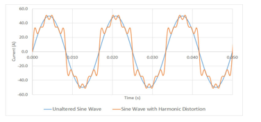 Figure 2: Current wave shapes: With and without distortion
Electrical generator systems that employ electronic switching devices and circuits also present specific problems for WTGSU transformers. From a manufacturer perspective, design philosophies to minimize the Eddy current loss to redress for harmonic load currents are imperative. While harmonic filtering is particularly not a function of a WTGSU transformer, magnetic shields strategically positioned between the windings may act as filters to mitigate the distorted harmonic currents into the collector bus. As a result, magnetic shielding should be deemed compulsory in the design of WTGSU transformers.
2.3. Switching Over-Voltages
A major concern with vast, wind turbine arrays is the necessity for connecting individual WTGSU transformers to the utility collector bus, leading to lengthy runs of cables. In large-scale wind facilities with a cluster of wind turbine towers, the WTGSU transformers may be positioned near the tower base as shown in Figure 1 in order to minimize the costs of large and lengthy runs of copper cables. Problems including excessive voltage drop, cable losses and risk of ground faults may arise from lengthy cable runs.
In view of the fact that wind energy facilities are in remote areas, they are more susceptible to lightning surges. As a result, surge arrestors must be mandatory for all WTGSU transformers.
Other things being equal, the biggest concern about switching over-voltages may be that generated by the wind turbines. On a 24-hours period, depending on the intermittent nature of wind; the wind turbines may be connected and disconnected online and offline when the wind speed increase and decline respectively. The latter may also occur when circuit breakers opens and closes the WTGSU transformer from the collector bus circuit. The switching phenomena by circuit breaker operation trigger transient over-voltages into the WTGSU transformers. This occurrence is aggravated by the application of vacuum circuit breakers, which have high-speed switching times. The fusion of the transient over-voltages and capacitance of the copper cables either HV or LV WTGSU transformer side may result in stationary waves and ringing that exceed the sinusoidal voltage amplitude as shown in Figure 3.
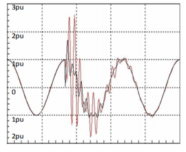 Figure 3: Typical switching surge [35]
Excessive transient over-voltages can trigger WTGSU transformer insulation failures. The transient over-voltages as shown in Figure 3 contains fast rise-time and high voltage amplitudes which clash with the resonant frequencies on the windings and can introduce electrical stresses exceeding the dielectric capability of the windings.
3. Winding Eddy loss under normal conditions
During service the winding conductor is immersed in an alternating magnetic field and subsequently the Eddy current start to flow. The energy loss dissipated as thermal energy on account of the Eddy current bring forth the Winding Eddy losses. The phenomena in rectangular winding conductors is demonstrated in Figure 4.
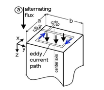 Figure 4: Harmonic current profiles [36]
The derivation of the winding Eddy loss formulae is reliant on factors suchlike frequency, local flux density and the winding conductor material properties. Provided that a winding conductor has the parameters as indicated in Figure 4 namely the, length, height and thickness are denoted by L, h and τ respectively. Then the alternating magnetic flux characteristic that is perpendicular to the height and thickness can be described by the eq. (1).
![]() Taking into consideration a closed-path in a clock-wise direction as shown in Figure 4, of thickness dx and distance x, a presentation of a single conductor with an induced voltage in closed-path is established. The area of this closed-path is expressed as follows in Eq. (2).
Taking into consideration a closed-path in a clock-wise direction as shown in Figure 4, of thickness dx and distance x, a presentation of a single conductor with an induced voltage in closed-path is established. The area of this closed-path is expressed as follows in Eq. (2).
![]() The amount of magnetic flux passing through the unit area in eq. (2) is expressed as follows in Eq. (3).
The amount of magnetic flux passing through the unit area in eq. (2) is expressed as follows in Eq. (3).
![]() It follows then, that the amount of magnetic flux characteristic that is perpendicular to the height and thickness in the closed-path can be described by the eq. (4).
It follows then, that the amount of magnetic flux characteristic that is perpendicular to the height and thickness in the closed-path can be described by the eq. (4).
![]() The induced voltage in the closed-path can be expressed in accordance with the Faradays law of induction as expressed in Eq. (5).
The induced voltage in the closed-path can be expressed in accordance with the Faradays law of induction as expressed in Eq. (5).
![]() Equating the constant 4.44=√2 π yields the formula in Eq. (6)
Equating the constant 4.44=√2 π yields the formula in Eq. (6)
![]() Taking into account the amount of magnetic flux passing through the closed-path unit area the eq. (6) yields the formula expressed in Eq.(7).
Taking into account the amount of magnetic flux passing through the closed-path unit area the eq. (6) yields the formula expressed in Eq.(7).
![]() Substituting the area of the closed-path in the induced voltage formula in Eq. (7) yields eq. (8).
Substituting the area of the closed-path in the induced voltage formula in Eq. (7) yields eq. (8).
![]() The resistance of the closed-path can then be expressed as follows in Eq. (9).
The resistance of the closed-path can then be expressed as follows in Eq. (9).
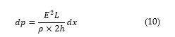
![]() The winding Eddy loss in the closed-path dx is then expressed as shown in Eq. (10). Considering that the thickness of the closed-path is extremely small in relation to the height, then the distance x I negligible.
The winding Eddy loss in the closed-path dx is then expressed as shown in Eq. (10). Considering that the thickness of the closed-path is extremely small in relation to the height, then the distance x I negligible.
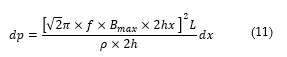
 Substituting eq. (7) into eq. (10) yields the expression in Eq. (11).
 Equating the constant √2 π=4.44 in Eq. (11) yields the formula in Eq. (12).
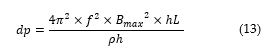
![]() Removing the square and expressing each terms to the exponent 2 yields eq. (13).
Removing the square and expressing each terms to the exponent 2 yields eq. (13).
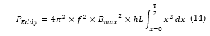
 Integrating both sides of Eq. (13) and considering the closed-path then the Eddy loss can be derived using Eq. (14).
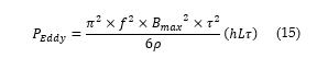
 Subsequently, the solution can be expressed as follows in Eq. (15).
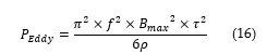
 Dividing the Eddy loss by hLτ equates to the area per unit volume as expressed in eq. (16).
 Finally, the Winding Eddy loss at fundamental frequency is expressed as follows in Eq. (17).
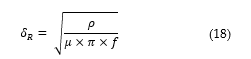
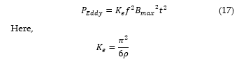 The skin depth of penetration at fundamental frequency 50Hz may be calculated as follows in Eq. (18).
 The depth of penetration under HLC is then computed as follows in Eq. (19).
 In principle, the following conclusions can be drawn with regards to the Eddy current loss in relation to the area per unit volume of winding conductor based on this derivation:
- There is a direct proportion to the fundamental frequency, conductor dimension and local flux density.
- There is an inversely proportional relationship to the resistivity of the copper conductor.
4. Transformer winding Eddy loss weighting factor
4.1. Winding Eddy loss under harmonic current loading
The winding Eddy loss along a winding height (H) can be expressed as follows in Eq. (20) [37].
![]() The standardized winding Eddy loss is then expressed by dividing eq. (18) with the rated copper loss to yield eq. (21).
The standardized winding Eddy loss is then expressed by dividing eq. (18) with the rated copper loss to yield eq. (21).
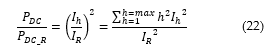
![]() Taking into consideration that the copper loss has a directly proportional relationship with the root mean square (RMS) load current under harmonic conditions [38-40] then first part of eq. (21) yields Eq. (22).
Taking into consideration that the copper loss has a directly proportional relationship with the root mean square (RMS) load current under harmonic conditions [38-40] then first part of eq. (21) yields Eq. (22).
 The contribution of the second part of Eq. (20) is as expressed in Eq. (17). The magnetic flux leakage under harmonic conditions has a directly proportional relationship to the RMS load current as expressed in Eq. (23).
![]() Under harmonic current conditions, the current I is expressed in Eq. (24).
Under harmonic current conditions, the current I is expressed in Eq. (24).
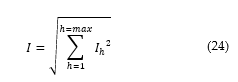 The harmonic current in Eq. (24) is expressed as . As such, the Eq. (24) yields Eq. (25).
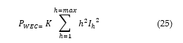 Here, the constant K is expressed in Eq. (17).
During service, when the transformer is operating at fundamental frequency, the equivalent rated winding Eddy loss is expressed as shown in Eq. (26).
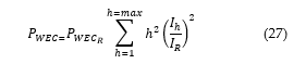
![]() Combining Eq. (25) and Eq. (26), the winding Eddy loss for a transformer operating under harmonic current can be expressed as shown in Eq. (27).
Combining Eq. (25) and Eq. (26), the winding Eddy loss for a transformer operating under harmonic current can be expressed as shown in Eq. (27).
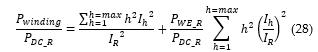
 Subsequently, combining Eq. (22) and Eq. (27) yields Eq. (28). This equation is formulated on the premise that induced current is at fundamental load current of the transformer during service.
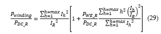
 Further simplification of Eq. (28) yields Eq. (29).
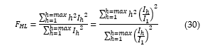
 The allowance made in order to take into account of the harmonic load current in relation to their effects on transformer thermal performance is then expressed as follows in Eq. (30).
 In principle, the following conclusions can be drawn with regards to the Eddy current loss under harmonic current loading:
- The winding Eddy loss is directly proportional to the RMS load current and the harmonic order. This relationship is similar in the computation of the stray loss in tank walls, core clamps et cetera except that the harmonic order is expressed to an exponent of 0.8 [35].
- The skin effect is not taken into consideration at high harmonic order. The magnetic flux under these conditions does not completely penetrate the surface of the winding conductors.
In the next section, a weighted loss factor that considers the skin effect is derived.
4.2. Winding Eddy loss under harmonic current loading
The Eddy current problem form part to the area of quasi-stationary electromagnetic effects of conductors. Insomuch that, the displacement current enclosed by winding conductors may incessantly be ignored in relation to the conductive current. This is indeed the case even at high frequencies given that in practice only winding conductors comprising high electric conductivity are used. Eddy currents give rise to uneven dissemination of current density in a studied cross sectional area of a conducting conductor. This inherently leads to rise in joule heating as opposed to the state produced by direct current (DC). The Eddy currents and related uneven dissemination of the magnetic flux are known as the skin effect. The rise in current density give rise to resistive heating as opposed to the DC resistance as well as a reduction in the inductance. In addressing the skin effect problem, this study adopts the Maxwell equations in [38] and remodel these equations to treat the quasi-stationary electromagnetic effects of conductors. These equations are expressed as follows in Eq. (31) and Eq. (32).
 On the above equations an add-on of the Ohm’s law as expressed in Eq. (33).
![]() The electric field intensity must fulfil Eq. (34).
The electric field intensity must fulfil Eq. (34).
![]() Similarly, the magnetic field must fulfil Eq. (35).
Similarly, the magnetic field must fulfil Eq. (35).
![]() In investigating the dissemination of current, small but sufficiently long conductors are considered. The location of the conductors in a coordinate system as demonstrated in Figure 5. The height and ratio of these conductors fulfil the condition and the spatial dependence on the y-coordinate may be ignored with insignificant error. When the current flows in the z-coordinate, the magnetic field has one component as described in Eq. (36).
In investigating the dissemination of current, small but sufficiently long conductors are considered. The location of the conductors in a coordinate system as demonstrated in Figure 5. The height and ratio of these conductors fulfil the condition and the spatial dependence on the y-coordinate may be ignored with insignificant error. When the current flows in the z-coordinate, the magnetic field has one component as described in Eq. (36).
![]() In the same order, the electric field intensity has a single component as expressed in Eq. (37).
In the same order, the electric field intensity has a single component as expressed in Eq. (37).
![]() In the event that a winding conductor has the conductivity the permeability and time-variant harmoniously at angular frequency , by elimination the ordinary second-order differential Maxwell equations for magnetic field intensity vector is expressed as follows in Eq. (38).
In the event that a winding conductor has the conductivity the permeability and time-variant harmoniously at angular frequency , by elimination the ordinary second-order differential Maxwell equations for magnetic field intensity vector is expressed as follows in Eq. (38).
![]() Here, the constant k is expressed as shown in Eq. (39).
Here, the constant k is expressed as shown in Eq. (39).
![]() In investigating the skin effect in winding conductors with a spasmodic magnetic flux, the rectangular copper conductors in Figure 5 are considered.
In investigating the skin effect in winding conductors with a spasmodic magnetic flux, the rectangular copper conductors in Figure 5 are considered.
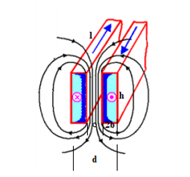 Figure 5: Two winding conductors immersed in alternating EMFs
The spasmodic magnetic flux streams along in the z-coordinate and the interaction of winding conductor 1 and 3 with respect to winding conductor 2 is investigated in terms of the winding Eddy loss under harmonic conditions. The effect of the remainder of winding conductors will be disregarded in order to presume that the impact of winding conductor 1 and 3 will be completely offset in the center winding conductor. Presupposing a harmonic time response of the 2nd order differential equation in Eq. (38), with the initial conditions necessitated for symmetry along the edges of the winding conductors shall be valid the equation and will yield the solutions in Eq. (40) and Eq. (41) as expressed below. It is evident that the solution in this case scenario is of nature.
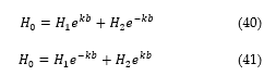 Here, is the root mean square (RMS) magnetic field strength. Additionally, the condition of is valid since the impact along the edges of the winding conductors is negligible if is satisfied. The constants of integration from Eq. (40) and Eq. (41) can then be expressed as follows in Eq. (42).
![]() The solution of the magnetic field strength presume the format expressed in Eq. (43).
The solution of the magnetic field strength presume the format expressed in Eq. (43).
![]() By association, the magnetic flux density by Eq. (42) is expressed as shown in Eq. (44).
By association, the magnetic flux density by Eq. (42) is expressed as shown in Eq. (44).
![]() Maxwell’s 1st equation in Eq. (33), can then be expressed as follows in Eq. (45).
Maxwell’s 1st equation in Eq. (33), can then be expressed as follows in Eq. (45).
![]() The constant k is introduced into the rationalization of the equilateral hyperbola as shown in Eq. (46).
The constant k is introduced into the rationalization of the equilateral hyperbola as shown in Eq. (46).
![]() The skin depth of penetration a under harmonic conditions may be calculated as follows in Eq. (47).
The skin depth of penetration a under harmonic conditions may be calculated as follows in Eq. (47).
 The skin depth at various harmonic orders is demonstrated in Figure 6.
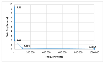 Figure 6: Depth of skin effect
The formulation of the current density is acquired and expressed as shown in Eq. (48).
![]() With the expansion of the equilateral hyperbola the modulus of the current density is expressed shown in Eq. (49).
With the expansion of the equilateral hyperbola the modulus of the current density is expressed shown in Eq. (49).
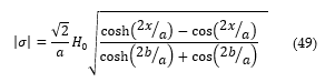 The dissemination of the magnetic flux density and current density along the surface of the winding conductors is described by Figure 7.
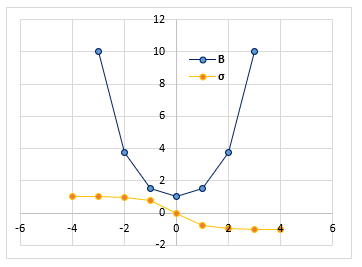 Figure 7: Distribution of the magnetic flux in the cross-section of a winding conductor
The magnetic flux leakage impinging upon one conductor is expressed by Eq. (50).
![]() The peak value of the magnetic flux leakage is given by Eq. (51).
The peak value of the magnetic flux leakage is given by Eq. (51).
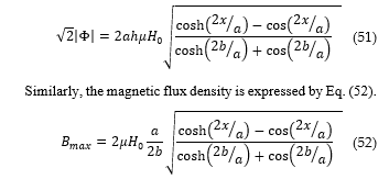 By employing Eq. (49) and introducing Eq. (52), the formulation of the current density is expressed as shown in Eq. (53).
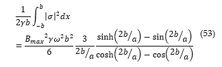 The variable is introduced here to account for expression of above as shown in Eq. (54).
![]() Forthwith, the Eddy loss per unit of volume of a winding conductor can be calculated using Eq. (17), where the weighted factor will be employed as expressed in Eq. (55).
Forthwith, the Eddy loss per unit of volume of a winding conductor can be calculated using Eq. (17), where the weighted factor will be employed as expressed in Eq. (55).
![]() Here, the weighting function that takes into consideration the skin effect in winding conductors under harmonic conditions is expressed as follows in Eq. (56).
Here, the weighting function that takes into consideration the skin effect in winding conductors under harmonic conditions is expressed as follows in Eq. (56).
![]() This function is presented graphically at different conductor dimensions as shown in Figure 8.
This function is presented graphically at different conductor dimensions as shown in Figure 8.
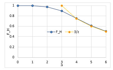 Figure 8: The function and
It is evident from Figure 8, that at higher harmonic order, the magnetic flux leakage does not completely penetrate upon the surface of the conductors. The latter addresses the short coming of Eq. (30).
5. Materials and Methods
In this section, a WTGSU transformer rated at 5000 KVA, 11000/33000 volts, 3-phase, 50 cycles, oil-immersed, naturally cooled (ONAN), core type, double wound with copper conductor and fitted with on load tap changer is studied. The temperature rise in oil and winding conductors is 50 ºC and 55 ºC respectively. The rated losses under consideration are at 75ºC on normal Tap position (in Watts) as shown in Table 1.
Table 1: Rated transformer losses
| Type of loss | Rated Losses (Watts) |
| No load | 4 500 |
| Copper | 25 000 |
| Winding Eddy | 938 |
| Other Stray | 1 253 |
| Total | 31 691 |
The studied transformer has a full load low voltage (LV) winding current of 262,43A with a mean winding Eddy loss at the highest loss ratio under rated conditions at 15% of the Copper losses.
The load that will been seen by the studied WTGSU transformer is described as shown in Figure 9. It is preferential that this harmonic load spectrum (HLS) to which the WTGSU will be susceptible be indicated to the transformer manufacturer during bid stage. A precise evaluation for the appropriate sizing of WTGSU transformers can only be designed by estimating the particular HLS.
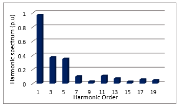 Figure 9: Harmonic Load Spectrum
The resultant HLFs and service losses are computed and discussed in the next section.
6. Results
6.1. Computation of Harmonic Loss Factor
It is handy to specify a single digit that may have recourse to evaluate the capability of the studied WTGSU transformer in facilitating power to the supplied harmonic spectrum above. This value viz. the harmonic loss factor (HLF) illustrates the effective RMS heating on account of the harmonic spectrum. The calculation of the HLF is tabulated in Table 2. The HLF by FEM is computed using the procedure described in [38].
Table 2: Computation of HLFs.
| h | IEC | Proposed | FEM | ||
| 1 | 0,97 | 0,941 | 0,941 | 0,941 | 0,941 |
| 3 | 0,37 | 0,137 | 1,232 | 1,090 | 1,213 |
| 5 | 0,35 | 0,123 | 3,063 | 2,569 | 2,924 |
| 7 | 0,1 | 0,010 | 0,490 | 0,100 | 0,448 |
| 9 | 0,028 | 0,001 | 0,064 | 0,063 | 0,055 |
| 11 | 0,11 | 0,012 | 1,464 | 1,455 | 1,184 |
| 13 | 0,071 | 0,005 | 0,852 | 0,807 | 0,640 |
| 15 | 0,026 | 0,001 | 0,152 | 0,135 | 0,106 |
| 17 | 0,057 | 0,003 | 0,939 | 0,925 | 0,600 |
| 19 | 0,047 | 0,002 | 0,797 | 0,774 | 0,468 |
| Total | 1,234 | 9,994 | 8,860 | 8,576 | |
| 1.111 | |||||
| HLF | 8,10 | 7,177 | 6,948 | ||
The ratio of the harmonic load current for each respective method and the RMS current (p.u) yields the HLFs as indicated previously.
6.2. Computation of Winding Eddy loss under harmonic current loading
The evaluation of the total service losses as a result of the HLC using the IEEE Std. C57.110-2018 is tabulated as shown in Table 3.
Table 3: Computation of total service losses: IEEE Std. C57.110-2018.
| Type of loss | Rated Losses (W) | Load Losses (W) | HLF | Service Losses (W) |
| No load | 4 500 | 4 500 | – | 4 500 |
| Copper | 25 000 | 30 859 | – | 30 859 |
| Winding Eddy | 938 | 1158 | 8,10 | 9 372 |
| Other Stray | 1 253 | 1547 | 1,58 | 2 442 |
| Total | 31 691 | 38 064 | 47 173 |
Under the supplied HLS, the service losses are witnessed to have a surge of about 33% and 19% from the rated and load losses respectively. The computation of the HLF for other stray loss in this work is similar to that of the winding Eddy loss as shown in Eq. (27), however these losses generated by metallic components such as tank walls, core clamp, windings, core, flitch plate et cetera are proportional to the square of the harmonic load current and the harmonic order to the exponent 0.8 as stated in [37]. The peak local load loss ratio for the HLC is computed as follows:
![]()
Given that the mean winding Eddy loss at the highest loss ratio under rated conditions is 15% of the Copper losses, then the load loss will be 1.15 p.u as shown below. The maximum permissible harmonic load current with the supplied harmonic spectrum is as follows:
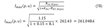 Consequently, with the supplied harmonic spectrum the studied WTGSU transformer capability is about 261.048A.
Table 4: Computation of total service losses: Proposed method
| Type of loss | Rated Losses (W) | Load Losses (W) | HLF | Service Losses (W) |
| No load | 4 500 | 4 500 | – | 4 500 |
| Copper | 25 000 | 30 859 | – | 30 859 |
| Winding Eddy | 938 | 1158 | 7,177 | 8 308 |
| Other Stray | 1 253 | 1547 | 1,58 | 2 442 |
| Total | 31 691 | 38 064 | 46 110 |
Under the supplied HLS, the service losses are witnessed to have a surge of about 31% and 17% from the rated and load losses respectively. The peak local load loss ratio for the HLC is computed as follows:
![]() By applying proposed method, the maximum permissible harmonic load current with the supplied harmonic spectrum is as follows:
By applying proposed method, the maximum permissible harmonic load current with the supplied harmonic spectrum is as follows:
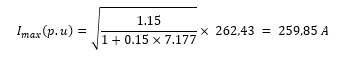 Consequently, with the supplied harmonic spectrum the studied WTGSU transformer capability is about 259,85A. The evaluation of the total service losses as a result of the HLC using FEM [38] is tabulated as shown in Table 5.
Table 5: Computation of total service losses: FEM
| Type of loss | Rated Losses (W) | Load Losses (W) | HLF | Service Losses (W) |
| No load | 4 500 | 4 500 | – | 4 500 |
| Copper | 25 000 | 30 859 | – | 30 859 |
| Winding Eddy | 938 | 1158 | 6,948 | 8 043 |
| Other Stray | 1 253 | 1547 | 1,58 | 2 442 |
| Total | 31 691 | 38 064 | 45 844 |
Under the supplied HLS, the service losses are witnessed to have a surge of about 31% and 17% from the rated and load losses respectively. The peak local load loss ratio for the HLC is computed as follows:
 Based upon the FEM procedure [38], the maximum permissible harmonic load current with the supplied harmonic spectrum is as follows:
 Consequently, with the supplied harmonic spectrum the studied WTGSU transformer capability is about 258,70A.
7. Conclusions
In the current work, an extension of the author’s previous work [29], new analytical formulae for the Eddy loss computation in transformer winding conductors have been explicitly derived, with appropriate contemplation of the fundamental and harmonic load current. These formulae allow the distribution of the skin effect and computation of the winding Eddy losses as a result of individual harmonics in the winding conductors. The rectangular winding conductors considered are based on real transformer geometries and represents the configuration of the conductors carrying harmonic load current.
The new formulae were triumphantly corroborated by comparing their performance with computationally intensive FEM simulations, authenticating their adequacy and efficacy. On that account, our findings are handy for the transformer manufacturing industry, where the transformer anatomy and design necessitate specific performance and inexpensive computational resources.
Additionally, it has been demonstrated that the harmonic load currents minimizes the depth of skin effect, lead to an increase in the copper losses and winding stray losses and, thereby, consideration must be given for proper evaluation and design of fir for purpose transformers capable of facilitating wind power. These formulae can be applied in the transformer design systems for calculating the effects of harmonics on the transformer active part components. These results can be utilized to enhance the design of transformer s and consequently minimize the generation of hotspots in metallic structures. In this way, the developed formulae are a critical furtherance to the existing methodologies employed by manufactures.
The method herein provides a fundamental basis for subsequent development such as analysis of thermal performance of transformers in wind power technologies.
Future work involves the development of TOC model for WTGSU transformers to evaluate their economic life by considering the intermittent nature of wind turbine generators.
Conflict of Interest
The authors declare no conflict of interest.
- Department of Energy, “Integrated Resource Plan (IRP2019)”, in 2019 Government Notice, 10-11, 2019, doi: IRP/2019/IRP-2019.pdf
- SAWEA,” South Africa’s Wind Industry. Stats and Facts SAWEA”, in 2020 Stats and Figures, 2020, doi: stats-and-facts-sawea.
- ESI Africa,”Tracking wind energy in South Africa”, in 2019 ESI Africa, 2019, doi: industry-sectors/renewable-energy/tracking-wind-energy-in-south-africa.
- M.A. Kamarposhti, S.B. Mozafari, S. Soleymani, S.M. Hosseini, “Improving the wind penetration level of the power systems connected to doubly fed induction generator wind farms considering voltage”, Journal of Renewable and Sustainable Energy, 7(4), 2015, doi.org/10.1063/1.4927008.
- J.M. Carrasco, L. Garcia Franquelo, “Power-Electronic Systems for the Grid Integration of Renewable Energy Sources: A Survey”, IEEE Transactions on Industrial Electronics, 53(4), 1002 – 1016, 2006, doi: 10.1109/TIE.2006.878356.
- A.A. Adly, S.K. Abd-El-Hafizb, “A performance-oriented power transformer design methodology using multi-objective evolutionary optimization”, Journal of Advanced Research, 6 (3), 2015, doi: org/10.1016/j.jare.2014.08.003.
- M.B. Mallett, “High-Voltage Power-Transformer Design”, in Transactions of the American Institute of Electrical Engineers, 62 (8), 1943, doi: 10.1109/T-AIEE.1943.5058737.
- B. A. Thango, J. A. Jordaan and A. F. Nnachi, “Step-Up Transformers for PV Plants: Load Loss Estimation under Harmonic Conditions,” in 2020 19th International Conference on Harmonics and Quality of Power (ICHQP), Dubai, United Arab Emirates, 1-5, 2020, doi: 10.1109/ICHQP46026.2020.9177938.
- B. A. Thango, J. A. Jordaan and A. F. Nnachi, “Effects of Current Harmonics on Maximum Loading Capability for Solar Power Plant Transformers,” in 2020 International SAUPEC/RobMech/PRASA Conference, Cape Town, South Africa, 1-5, 2020, doi: 10.1109/SAUPEC/RobMech/PRASA48453.2020.9041101.
- B.A. Thango, J.A. Jordaan, A.F. Nnachi, “Contemplation of Harmonic Currents Loading on Large-Scale Photovoltaic Transformers,” in 2020 6th IEEE International Energy Conference (ENERGYCon), Gammarth, Tunis, Tunisia, 479-483, 2020, doi: 10.1109/ENERGYCon48941.2020.9236514.
- J.N. Jagers, J. Khosa, P.J. De Klerk, C.T. Gaunt, “in 2007 Transformer Reliability and Condition Assessment in South African Utilities”, in 2007 XVth International Symposium on High Voltage Engineering. University of Ljubljana, Elektroinstitut Milan Vidmar, Ljubljana, Slovakia, 27-31, 2007, doi:10.1.1.533.6250.
- V.M. Motalleb, M. Vakilian, A. Abbaspour, “Tank shielding contribution on reduction of Eddy current losses in power transformers”, in 2009 IEEE Pulsed Power Conference. Washington, DC, 641-645, 2009, doi: 10.1109/PPC.2009.5386382.
- A.M. Milagre, M.V. Ferreira da Luz, G.M. Cangane, “3D calculation and modeling of eddy current losses in a large power transformer”, in 2012 XXth International Conference on Electrical Machines. Marseille, 2012, doi: 10.1109/ICElMach.2012.6350200.
- S. Saha, N. Fernando, L. Meegahapola, “Multi magnetic material laminated cores: Concept and modelling”, 2017 20th International Conference on Electrical Machines and Systems (ICEMS), Sydney, NSW, 2017, doi: 10.1109/ICEMS.2017.8056247.
- O. Bottauscio, M. Chiampi, D. Chiarabaglio, “Advanced model of laminated magnetic cores for two-dimensional field analysis”, IEEE Transactions on Magnetics, 36, (3), 561-573, 2000, doi: 10.1109/20.846219.
- A.I. Korolev, “On electromagnetic induction in electric conductors”, arXiv: Cornell University, 2013, doi: 1303.0785.
- V. Sarac, G.Stefanov, “ Calculation of Electromagnetic Fields in Electrical Machines using Finite Elements Method”, 2011 International Journal of Engineering and Industries 2(1), 2011, doi: 10.4156/ijei.vol2.issue1.3.
- A. Srikanta Murthy, N. Azis, J.Jasni, M.L. Othman, M.F. Mohd Yousof, M.A. Talib, “Extraction of winding parameters for 33/11 kV, 30 MVA transformer based on finite element method for frequency response modelling,” 2020 PLoS One, 15(8), e0236409, doi.org/10.1371/journal.pone.0236409.
- J. Íñiguez, V. Raposo, M. Zazo, A. García-Flores, “ The electromagnetic field in conductive slabs and cylinders submitted to a harmonic longitudinal magnetic field”, American Journal of Physics, 77, 1074, 2009, doi.org/10.1119/1.3160663.
- N. Amemiya, Y. Sogabe, S. Yamano, H. Sakamoto, “ Shielding current in a copper-plated multifilament coated conductor wound into a single pancake coil and exposed to a normal magnetic field”, Superconductor Science and Technology, 32 (11), 2019, 10.1088/1361-6668/ab3f1c.
- B.A. Thango, J.A. Jordaan, A.F. Nnachi, Analysis OF Distributed solar Photovoltaic System Harmonics on Transformers, Eliva Press, 2020.
- S.V. Kulkarni, S.A. Khaparde, Transformer Engineering: Design and Practice, Taylor & Francis Group, 2004.
- A. Mor, S. Gavril, “Eddy Current Effects on the Asynchronous Performance of the Hysteresis Machine”, Journal of the Franklin Institute. 314(2), 1982, doi.org/10.1016/0016-0032(82)90062-X.
- S.V Kulkarni, J.C Olivares, R. Escarela-Perez, V.K. Lakhiani, J. Turowski, “Evaluation of eddy losses in cover plates of distribution transformers”, IEE Proceedings – Science, Measurement and Technology, Vol. 151(5), 313-318, 2004, doi: 10.1049/ip-smt:20040632 .
- A. Najafi, I. Iskender, “ Reducing losses in distribution transformer using 2605SA1 amorphous core based on time stepping finite element method”, in 2015 International Siberian Conference on Control and Communications (SIBCON). Omsk, 2015, doi: 10.1109/SIBCON.2015.7146963.
- L. Betancourt, G. Martinez, D. Álvarez, J. Rosero, “Losses characterization on distribution transformer windings in frequency domain by means of finite element method (FEM): Part I”, in 4th International Conference on Power Engineering, Energy and Electrical Drives. Istanbul, 2013, doi: 10.1109/PowerEng.2013.6635589.
- G.U. Nnachi, A.O. Akumu, C.G. Richards, D.V. Nicolae, “ Estimation of no-Load Losses in Distribution Transformer Design Finite Element Analysis Techniques in Transformer Design”, in 2018 IEEE PES/IAS PowerAfrica, Cape Town, 2018, doi: 10.1109/PowerAfrica.2018.8521142.
- L. Susnjic, Z. Haznadar, Z. Valkovic,”Stray Losses Computation in Power Transformer”, in 2006 12th Biennial IEEE Conference on Electromagnetic Field Computation. Miami, FL, 2006, doi: 10.1109/CEFC-06.2006.1633280.
- B. A. Thango, J. A. Jordaan and A. F. Nnachi, “A Weighting Factor for Estimating the Winding Eddy Loss in Transformers for High Frequencies,” in 2020 6th IEEE International Energy Conference (ENERGYCon), Gammarth, Tunis, Tunisia, 2020, doi: 10.1109/ENERGYCon48941.2020.9236472.
- H. Kekana, G. Landwehr, “Wind capacity factor calculator”, Journal of energy South. Africa, 30 (2), Cape Town, 2019, doi: https://dx.doi.org/10.17159/2413-3051/2019/v30i2a6451.
- B.A. Thango, J.A. Jordaan, A.F. Nnachi, “ Total Ownership Cost Evaluation for Transformers within Solar Power Plants”, in 2020 6th IEEE International Energy Conference (ENERGYCon).Gammarth, Tunis, Tunisia, 2020, doi: 10.1109/ENERGYCon48941.2020.9236613.
- C.A. Charalambous, A. Milidonis, A. Lazari, A.I. Nikolaidis, “Loss Evaluation and Total Ownership Cost of Power Transformers—Part I: A Comprehensive Method”, IEEE Transactions on Power Delivery, vol. 28 (3), 2013, doi: 10.1109/TPWRD.2013.2262506.
- J.F. Baranowski, P.J. Hopkinson, “An alternative evaluation of distribution transformers to achieve the lowest TOC”, IEEE Transaction Power Delivery, 7, 1992, doi: 10.1109/61.127057.
- A.L. Lazari, C.A. Charalambous, “Probabilistic Total Ownership Cost of Power Transformers Serving Large-Scale Wind Plants in Liberalized Electricity Markets”, IEEE Transactions on Power Delivery, vol. 30(4), August. 2015, 10.1109/TPWRD.2014.2365832.
- F. Lee and T. Wilson, “Voltage-spike analysis for a free-running parallel inverter,” in IEEE Transactions on Magnetics, 10 (3), 969-972, 1974, doi: 10.1109/TMAG.1974.1058474.
- D. Kusiak, “The Magnetic Field and Impedances in Three-Phase Rectangular Busbars with a Finite Length”, Energies 2019, 12(8), 1419, doi.org/10.3390/en12081419.
- IEEE,” Recommended Practice for Establishing Liquid Immersed and Dry-Type Power and Distribution Transformer Capability when Supplying Nonsinusoidal Load Currents”, in IEEE Std C57.110-2018, 2018, doi: 10.1109/IEEESTD.2018.8511103.
- B.A. Thango, Jordaan, A.F. Nnachi, “A Novel De-rating Procedure for Distributed Photovoltaic Power (DPVP) Generation Transformers”, in 2021 International SAUPEC/RobMech/PRASA Conference, 2021, doi: 10.1109/TPWRD.2013.2262506.