
Designing and Implementation of an Intelligent Energy Management System for Electric Ship power system based on Adaptive Neuro-Fuzzy Inference System (ANFIS)
Volume 6, Issue 2, Page No 195-203, 2021
Author’s Name: Mohab Gaber1,2,a), Sayed El-Banna2, Mahmoud El-Dabah2, Mostafa Hamad3
View Affiliations
1Egyptian Navy R&D Center, Alexandria, 21613, Egypt
2AL-Azhar-University, Cairo 11865, Egypt
3Arab Academy for Science, Technology & Maritime Transport-Alexandria, 1029, Egypt
a)Author to whom correspondence should be addressed. E-mail: mohab_gaber@ieee.org
Adv. Sci. Technol. Eng. Syst. J. 6(2), 195-203 (2021); ![]() DOI: 10.25046/aj060223
DOI: 10.25046/aj060223
Keywords: ANFIS, Battery State of Charge (SoC), Electric ships, Energy Management System, Fuel Cell, Greenhouse Emission, Integrated power system, Load demand

Export Citations
Artificial Intelligence (AI) is a promising trend in ship energy management systems (EMS).
The motivations of this work are designing and implementation of an intelligent energy management system for ship’s electric power system based on an adaptive Neuro-Fuzzy Inference System (ANFIS) and the ship power source is an environmental friend system consists of proton exchange membrane fuel-cell (FCPM) considered as the main power source and battery bank as an electric storage system using (ANFIS) to manage the fuel cell generation by solving the optimization problem to reduce the Hydrogen fuel consumption and ensure the system balance.
The benefit of using this technique is to penetrate a new field of using renewable and sustainable energy sources in marine to reduce greenhouse emission and increase the sailing period, system reliability by interfacing with the ship’s integrated power system.
The simulation of this system is carried out by MATLAB® software and (EMS) is implemented to test rig hardware with computer and interface card to emulate the ship’s electric power system. The results obtained from the simulation are compared with the experimental results for the evaluation of the EMS performance.
Received: 13 December 2020, Accepted: 16 February 2021, Published Online: 10 March 2021
1. Introduction
Traditional marine power plants mainly are intended to move fossil fuel and gas turbine, which is the major source of NOx and the dominant sources of total hydrocarbons (THCs) from Cox and Particulate Matters, causing air pollution [1], and reducing the ship’s running costs [2]. Researchers recently started to analyze the air quality in the Pearl because of the current emissions of ships [3], to analyze the characteristics of ship emissions [4], and to analyze the effects of air pollution emissions from the ship [5]. To substitute fossil fuel, renewable energy solar and wind power, fuel cells, and hydrogen, clean-fuel options such as Liquefied natural gas (LNG), methanol, and ethanol should be proposed [6]. Ship power plant applications should be proposed.
Clean energy will achieve the target for saving energy and reducing the ship’s emission however using a single energy source is not a satisfactory solution because it is affected by meteorological conditions that are not constant [7]. The restriction from the International Maritime Organization (IMO) to control the greenhouse gas emission from the ships allows using renewable energy in a wide range [8]. So the shipbuilders began to take the trend of zero-emission ships [9].
Also, using autonomous ships that can sail for a long time without refueling[10]. Renewable energy provides the ship’s electrical power with high-efficiency power, less noise, and near-zero-emissions than the conventionally used fossil fuel [11].
Going toward green ships became obligatory conditions, All-Electric Ship (AES) technique which moving toward replacing the ship’s power system, with electric power sources [12] with the clean, safe, cheap and, smart sources that are renewable energy sources such as solar, wind and fuel-cell systems [13], [14]. The broader areas of ports suffered from pollution by shipboard emissions when berthing so the U.S. Navy initiate European project EL-EMED namely the introduction of “Cold ironing” in the East Mediterranean to relieve the port from ship pollutions and going toward “greener” energy (e.g. renewables) to support the effort [15].
Using fuel cells for ship electric propulsion becomes a new challenger in the ship power system because it has good dynamic performance and maintenance-free so it’s recommended in autonomous ships. On the other hand, limiting the power of fuel cells is another issue so fuel cells are used as an emergency source in the more electric aircraft techniques and special missions in naval ships that need a low acoustic signature like submarine seeking [16].
Improving the dynamics and power density of fuel-cell systems required to be combined with energy storage systems such as supercapacitors and batteries.
Another technique to enhance the performance of the fuel cell hybrid system by adding a renewable photovoltaic array that can reduce fuel consumption to 50% [11].
The system optimization is accomplished by an energy management strategy (EMS), to achieve economic fuel consumption and ensure providing the load with sufficient energy. Another factor is to maintain the system lifetime for each of the hybrid power systems as long as possible [17].
The advance of power systems that use renewable energy resources besides the revolution of power electronics forced fastly the development of artificial intelligence techniques [18, 19].
Using Artificial intelligence in the power system in operation, transmission, transient, protection, and control increases the stability of the power system, improves its output efficiency, and ensures system protection than classical protections [20-22].
The system proposed in this work is state of the art and the most common system used in different applications in industrial, aerospace [23], terrestrial, marine applications, and recently in traction systems. the difference between these systems is the energy management techniques.
Using adaptive neuro-fuzzy inference system in ship’s power system combined the advantage of fuzzy and neural technique these procedures used to recognize the scheme Fault Analysis [24], estimate the system worth [25], development the power system effectiveness and lately to achieve the energy generated from the hybrid system to accomplish the economical use of fuel with best system performance. ship’s electric power system is the same as any power system and starts the competitor of the improvement with a terrestrial power system [26].
In this system, the load demand and the battery state of charge (SOC) are the (EMS) input for identifying the adequate fuel cell power as system output based on solving the optimization problem to reduce the fuel consumed and ensure the system balance.
2. Ship smart grid power system
The ship’s electric power system can be considered as an island microgrid during sailing and grid connecting in the port. Complex problems due to the existence of more than non-homogeneous power sources in hybrid systems had the solutions is the smart grid which is an important application in artificial intelligence (AI) and computational intelligence (CI).
In naval and commercial ships, the higher amount of information for the propulsion system, service equipment, and combat system naval ships need to be processed to decide the decision, AI and CI offer perfect solutions by centralized or distributed intelligence. The huge amount of information processing in the smart grid systems with computation intelligence (CI) for supporting the decision.
Artificial intelligence is working as a human brain that concerning decision-making capabilities such as search methods, knowledge representation, inference techniques, and machine learning [27].
CI techniques contain expert systems, genetic algorithms (GAs), fuzzy logic, artificial neural networks (ANNs), and adaptive neuro-fuzzy interface system (ANFIS). CI includes adaptive mechanisms for intelligent behaviors in complex systems, such as the ability to adapt and generalize. These techniques provide a new challenger for the field of ship smart grids and the application of the computer in power engineering.
AI and CI offer the best tools for the shipboard operation, maintenance, monitoring, in addition to risk management.
Ship smart grid technologies manage the uncertainties, increasing complexity, and highly nonlinear nature of hybrid electric power systems such as in-vehicle applications, and also in Autonomous Vehicles [23, 28, 29]. The adaptive Neuro-Fuzzy Interface system (ANFIS) which we use in this work, is an Artificial Intelligence technique that mimics human brain behavior. Due to its learning and generalization capabilities, ANFIS can be expressed as a mathematical representation of the human neural architecture. The accuracy of the energy management system in naval electric ships is important to ensure the availability of power in all modes of operations [30].
The adaptive neuro-fuzzy inference system (ANFIS) is a fuzzy inference system that uses a hybrid learning algorithm for training. ANFIS is a powerful technique used for predictive control and energy management in critical applications such as More Electric Aircraft (MEA) and hybrid smart grid [31] and in the systems that consist of Fuel cell and battery in different applications [32], [33]. As the industrial revolution and technology base for communication increases, electric shipboards power can be easily interfaced with a comprehensive computer program to handle energy saving and monitoring smartly and can also be used as fault diagnosis. The Internet of things makes interface these systems simple for navigations, especially in naval and autonomous ship applications in case of hazardous or dangerous locations, with a safe communication system for control and remote control [34].
- System description
In naval ships, one of the difficult missions during sailing is the “submarine seeking” this mode of operation requires silent sailing performing a low acoustic signature to avoid submarine torpedo and missile because of the torpedo and missile lock on the ship noise.
The proposed model is a common hybrid model[23] consists of the main DC power source from a fuel-cell and storage system of
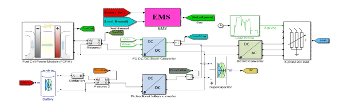 Figure 1: The model of hybrid power system for ship’s silent mission
battery banks and super-capacitor. This model is enhanced by adding another energy source as a solar energy source (PV module)
or diesel generator according to the ship application and the load demand.
The proposed hybrid model is designed based on the power requirement for the silent mission. The absence of mechanical equipment results in low acoustics signature the model as shown in Figure 1.
A 12.5 kW proton exchange membrane (PEM) fuel-cell power module, the system is designed to meet the average demand of 10 kW, to compensate for the slow dynamics of FCPM an energy storage system is incorporated with two series battery type Sonnenschein A 412/100 A (13.6 V, 100 Ah) working alone or with super-capacitor (48.6 V, 88F). The fuel-cell energy and battery energy are controlled across dc/dc converters which are determined by the output voltage reference and a max input/output current reference (fuel cell output power) from the energy management. The battery converter is bi-direction to charge/ discharge the battery the super-capacitor is neglected in this energy management system due to the short using time. The DC bus is the output of the two converters and connected to the input side of the inverter which converts the dc power to three-phase output power controlled the voltage and the frequency connected to programmable load profile power. This system is a generic system used in different applications with different power ratings with different energy management techniques. It is used in the more electric aircraft techniques and traction for trains and electric vehicles.
4. Energy management system architecture
The Architecture of the proposed Energy Management System (EMS) is as shown in Figure 2 where the ANFIS controller has two inputs and one output. The inputs to the EMS are the load power and the battery State of Charge SoC, these inputs injected into the EMS to sense the performance of the system toward the loading and calculate depending on the training data the predictive energy from the fuel cell .
The load in the model can be modified according to the ship operation. depending on the experience, the load is pre-set to the model by programmed load profile and measure from the three-phase sides. A three-phase inverter with a sufficient rating converts the DC power to AC power with controlled volt and frequency. The predictive fuel cell power is used to measure the max fuel cell current which is injected into the fuel cell DC/DC converter as a reference to the fuel cell converter. the max fuel cell current is injected into the fuel cell controller to calculate the sufficient amount of hydrogen fuel and air needed for the fuel cell as shown in Figure 2.
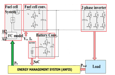 Figure 2: The architecture of the energy management system
The DC/DC battery converter is a bidirectional converter with two modes charging and discharging the controller to calculate the necessary battery current according to the battery SoC and determine which mode is active. Table 1 show the energy management-designed parameter requirement.
Table 1: Energy Management Design Parameter.
| Parameters | Minimum | Maximum |
| Fuel cell power | 1 | 10 |
| Battery Power | -2.4 KW (charging) | 4 KW (discharging). |
| Battery SoC (high) | 85% | 100% |
| Battery SoC (normal) | 65% | 85% |
| Battery SoC (low) | 40% | 65% |
| DC bus Voltage | 250V | 280V |
5. System optimization problem
Hybrid systems that use at least two energy sources for providing the load with its needed power. that system is usually combined with one or more renewable energy sources, energy-storing systems, or fuel systems that may be the engine with fossil fuel or hydrogen. Hybrid systems are expected to have an optimization technique working with the (EMS) which identifies which source provides the load with its necessary power or how much power should provide for each source to reduce the fuel consumption and ensure the system stability[35]-[37].
For achieving this goal, the optimal minimization and control strategy is applied to the hybrid system component fuel cell, supercapacitor, and battery to produce the reference power determined by the EMS based on the load demand[23]. The electric power produced from the fuel cell and the energy storing system battery and supercapacitor should be converted to equivalent hydrogen consumption.
The calculation of the equivalent of the hydrogen consumption for load C that is the sum of fuel cell hydrogen consumption and battery hydrogen consumption and supercapacitor hydrogen consumption .
The equivalent mathematical problem for minimizing fuel consumption is the following:
![]() where fuel cell output power
where fuel cell output power
and penalty coefficients converter to hydrogen consumption.
The supercapacitor power is neglected in the optimization problem because the battery converter controls the dc-bus voltage. And the discharging or charging of the supercapacitors within the same energy from the battery system so the load power is divided between the fuel cell and the battery in each cycle. The optimization problem can be written as:
 The battery equivalent hydrogen consumption can be calculated from the battery power and the battery SoC Under the equality constrains
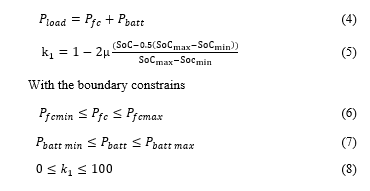 The above is the system cost function which is a generic problem for any hybrid system consists of fuel cell energy storing devices and this multi-objective optimization problem is solved for this system in several papers which is not interest in this issue [36], [38], [39].
6. Proposed (ANFIS) energy management system
With the spread of fuzzy techniques in the control applications, the developers look for an automatic learning process to supporting the industrial applications. The Adaptive Neuro-Fuzzy Inference System (ANFIS) was a solution to combine the advantage of both the learning ability of artificial neural networks (ANN) and the inference capability of rule-based fuzzy logic control to obtain a complete set of all kinds of feed-forward neural network with supervised learning capability. ANFIS technique achieves the hybrid learning procedure between the input-output relationship depend on the expert knowledge and input-output data. ANFIS become effective in modeling the nonlinear systems, identifying the nonlinear parameters in real-time control in the complex control in the complex electrical system, called Integrated Power System (IPS), which can be considered equivalent to an islanded power grid, and predicting the parameters like course keeping autopilot in ship sailing and weather forecasting [31], [32].
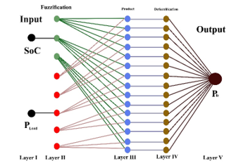 Figure 3 The proposed (ANFIS) structure
MATLAB provides a powerful simulation and test platform which will be used in this work. Figure 4. shows the structure of the MATLAB layered ANFIS implemented in this model. ANFIS design contained just one hidden layer as shown in Figure. 3, the system is composed of five nodes, layer_1 the input nodes, Layer_2 the fuzzification nodes, Layer_3 the product nodes(hidden), layer_4 the defuzzification nodes, and Layer_5 the output node. Besides, some nodes will be classified as adaptive or fixed nodes based on whether they can be updated.
Later_2 and Layer_4 denote as the adaptive nodes and
Layer _1, 3 are the fixed nodes. To predict the power output of the fuel-cell, the inputs to the ANFIS are the battery SoC in three MF, and the consumed ship power load . The output of the ANFIS is the predicted output power from the fuel cell value PFC. By applying the relative parameters, the ANFIS generates the rules and tunes efficiently.
7. ANFIS Control Procedure
ANFIS procedure will be carried out according to the learning result that pre-obtained from the old trial or human experience and this is the benefit of using ANFIS, especially the non-linear systems and the systems that need a quick decision in real-time.
In this system, the generic energy management system will introduce independent on the application the system with fuel cell and storage system (battery, super-capacitor) can be used in aircraft, ship or cars the only difference is the objective of the EMS for Aircraft safety is the highest objective for naval ships the reliability is the highest objective for cars minimizing the fuel consumption.
Two inputs are the EMS’s inputs see Figure 4. The first input is the battery SoC that indicates the battery state and the amount of power that it has, the optimal state is the normal state between
65% to 85% [34]. Another objective is to maintain the battery state of charge SoC within normal SoC to increase the battery lifetime. The second EMS input is the ship’s load power. The permissible fuel cell power between 1-10 kW to ensure the system balance.
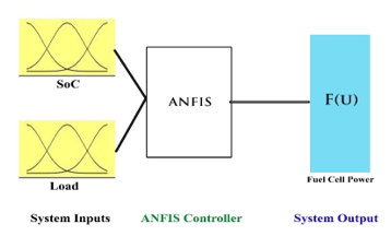 Figure 4: MATLAB Simulation ANFIS Model
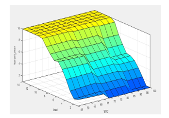 Figure 5. The MATLAB Simulation Output Surface of The ANFIS.
ANFIS model contained a closed-loop control system depends on the previous expert data. The accuracy of the system output is affected by ANFIS training data. In this system, ANFIS is trained to get the membership function (MFs), by (2352) training data among SoC, load power, and the fuel cell power to allow the ANFIS to estimate a good correlation between inputs and output. The expert data entered into the system (3ꭓ784) input-output trial is used to develop the controller with minimum error.
To minimize the error (6000) epochs is performed to minimize the training errors till (1×10⁻⁴) the training error less than 0.0001 this means the ANFIS system output is almost the desired concerning the training values. The output surface obtained from the ANFIS is shown in figure 5.
8. Simulation test results
The simulation result will be carried out using the MATLAB ANFIS editor for three-mode SoC High, Normal and low the system parameters are shown in the Table 1.
For testing the EMS the load power will be changing as the load profile to obtain the estimated fuel cell power the EMS calculates the max fuel cell current ( which is used as a reference to the fuel cell air and hydrogen controller to determine the amount of fuel needed for the fuel cell, ( are calculated references determine by EMS for the DC/DC fuel cell converter to control the DC bus voltage within the limits mentioned in Table. I and enabling the state of the bi-directional DC/DC battery converter charging or discharging according to the system parameters load, battery SOC, and the calculating fuel cell power.
Figure 6 shows the ANFIS MATLAB simulation editor in case of battery normal SOC.
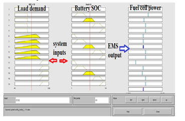 Figure 6: The MATLAB Editor Test
The simulation is carried out under three battery modes of operation. Table 2 shows the results obtained from the ANFIS editor in MATLAB the left column is the load demand changing from (1-12) kW. The second column is the EMS predictive power drawn from the fuel cell at high SoC mode 90%. The third column is the fuel cell’s at normal SoC mode 75%, and The last column is the predictive fuel cell’s power at low SoC mode50%.
The battery State of Charge indicates the percentage of battery capacity. The battery power depends on the battery SoC, because that it should be balanced between charging/discharging in normal SoC mode to get better performance and for reservation its lifetime[40, 41].
Table 2: Simulation Result Obtained from ANFIS EMS
| high
SoC |
Normal
SoC |
low
SoC |
|
| 1 | 1 | 1 | 2 |
| 2 | 1 | 2 | 2 |
| 3 | 2 | 3 | 4 |
| 4 | 2 | 4 | 4 |
| 5 | 4 | 5 | 6 |
| 6 | 4 | 6 | 6 |
| 7 | 6 | 7 | 8 |
| 8 | 8 | 8 | 8 |
| 9 | 8 | 9 | 10 |
| 10 | 10 | 10 | 10 |
| 11 | 10 | 10 | 10 |
| 12 | 10 | 10 | 10 |
Results in Table 2 show that the fuel cell power varies according to the battery SoC. ANFIS system is trained to provide the load with sufficient power and maintain the battery SoC in normal mode. the test had performed under their mode of operations high SoC at 90%, normal SoC 75%, and low SoC at 50%.
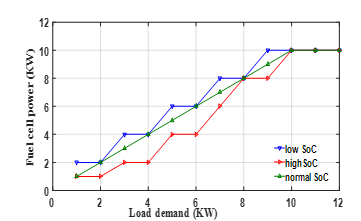 Figure 7: Fuel cell – Load Demand for Different Mode of Operations
The results obtained from the ANFIS system are shown in figure7.
The green line indicates the normal SoC mode of 75%.
In this mode, the EMS produced power from the fuel cell equal to the load demand to supply the load and maintain the battery at its normal SoC.
The red line indicates the high SoC mode of 90%.
In this mode the battery storage power is high so the EMS produces power from the fuel cell less than the load demand power to supply the load and obtained power from the battery to reduce the battery mode from high SoC to normal SoC. The red line is under the green line (that indicates the load demand) because the fuel cell produced power (area under the curve) is less than the load demand and the remaining power is obtained from the battery.
The blue line indicates the low SoC mode in this mode the battery power is low so the EMS produced power from the fuel cell greater than the load demand power to supply the load and charge the battery to increase the battery SoC from low to high SoC. The blue line is over the green line that means the power produced from the fuel cell is greater than the load demand.
In the third column the battery at normal SoC so the EMS produces power from the fuel cell equal to the load demand to maintain the battery SoC at normal mode. In the fourth column at low SoC, there is a shortage in the battery power so EMS produce power from fuel cell greater than the load demand to supply the load and charging the battery to increase the battery SoC from low to normal SoC.
The intelligent EMS trained to maintains the change in the fuel cell power in constant steps to avoid fluctuation in the ship electric grid. The intelligent EMS using the storage energy system to overcome the sudden and continuous change in load instate of step up or step down the fuel cell power because of the slow response of the fuel cell as a result of the chemical reaction.
EMS limiting the fuel cell output power at the maximum allowed the power of 10 kW although the load demand reaches 12 kW the remaining power is drawn from the batteries.
If the load demand exceeds this value, the protection device will disconnect the load.
9. Laboratory experimental simulation
To verify the proposed ANFIS Energy Management System control method in a real-time system, a test rig is built as shown in figure 8. with two dry gel lead, acid battery model Sonnenschein A412/100A 100Ah this battery offers excellent performance and suitable to work in marine applications and used in the field of unmanned surface vehicles USV. The battery will have been charged through a battery charger connected to the SOC sensor signal conditioner model 480E09 to indicate the battery state of charge.
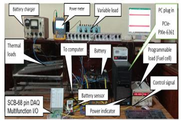 Figure 8: laboratory test rig for ANFIS EMS.
Thermal loads 6X1 KW and three variable loads with 2X3 kW is connected to the system as system load smart Fluke multimeter is connected to the system to verify the drawn load the PC is plug in PCIe-6361 DAQ card connected to multifunction SCB-68 with 68 pins connected to the input and output signals SCB-connected to the PC across the data-parallel cable. The programmable power supply working as a fuel cell to provide the system with the necessary DC power.
The input signal the pc is connected through the SCB-68 module as follow
- SOC from battery sensor conditional as 4-20mA.
- System load from smart Fluke multi-meter as RS232.
- The output signal 4-20mA connected to the programmable
- power supply through the yellow control cable as shown in Figure 8.
The power supply has two screens one for the DC voltage and the other is the power supplied from the supply.
NI-DAQmx9.2 drive software is installed on the PC to interface the system with the ANFIS.
10. Experimental test procedure
The schematic diagram of the system is shown in Figure 12. which shows the control modules contains from the PC with the DAQ system plug in the PC and the interfacing to the system sensor hardware through the cable and NI-DAQmx 9.2 software in the center of the diagram.
- The system inputs are in purple lines
- ( &battery SoC)
- The system output is green lines that indicate if the battery charging/discharging and the signal to the fuel cell to produce sufficient power to the system.
The test is carried out in three modes
- Battery SoC high above 85%
- SoC normal between 85 and 65%
- SoC low between 65% to 45%.
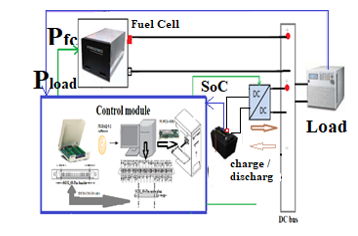 Figure 9: Stricture for ANFIS Laboratory Test Rig.
For each mode of charge, the load will change manually from
0 to 12kW and the ANFIS sends the signal to the DC programmable power supply which is scaled before from 4-20mA control signal to produce power from 0-10KW.
The produced power is shown in the left monitor from the power supply as shown in Figure 8.
Table 3 shows the fuel cell power produced in the experimental test.
The experimental results show in Table 3 have the same concept in the simulation results in high SoC the EMS produces less power the demand load power to degrease the battery SoC to the normal SoC. The third column is the normal Soc which almost the load demand power to maintain the battery SoC at normal mode. The last column is the battery low SoC that EMS produces power from the fuel cell to charge the battery and supply the load.
Table 3: The Real-time Result Obtained from ANFIS EMS
| high
SOC |
normal
SOC |
low
SOC |
|
| 1 | 0.9 | 0.95 | 1.9 |
| 2 | 0.9 | 2.01 | 1.95 |
| 3 | 2.05 | 3.01 | 3.95 |
| 4 | 2.05 | 4 | 4 |
| 5 | 4.02 | 5 | 5.8 |
| 6 | 4.02 | 5.95 | 6 |
| 7 | 6 | 7.01 | 7.9 |
| 8 | 8.01 | 8. | 8 |
| 9 | 8. | 9.01 | 9.8 |
| 10 | 10 | 10 | 10 |
| 11 | 10 | 10 | 10 |
| 12 | 10 | 10 | 10 |
10.1. Battery normal state of charge mode
In this mode, the battery SoC 90 % and starting to change the system load from 0 to 12KW the values obtained in this case in Table 3 will compare with the values from the simulation for the same SoC in Table .2. Figure 10. Shows the experimental results in red dashed line and the simulation result in blue dotted lines and the two curves are identical the same.
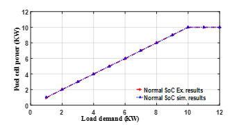 Figure 10: Real-time and Simulation Result at Normal SoC 75%
10.2. Battery high state of charge mode. 90%.
In this mode, battery high SoC 90 % mode and starting to change the system load from 0 to 12kW the values obtained in this case Table 3 will compare with the values from the simulation for the same SoC in Table 2. Figure 11. Shows the experimental results in the red dashed line and the simulation results in blue dotted line and the two curves are almost identical. The green solid line is the load demand.
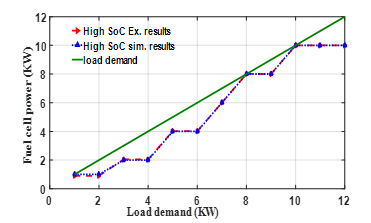 Figure 11: real-time and simulation result at normal SoC 75%
10.3. Battery low state of charge mode 50%
In this mode, the battery low SoC 90 % mode and starting to change the system load from 0 to 12kW the values obtained in this case Table 3 will compare with the values from the simulation for the same SoC in Table 2. Figure 12. Shows the experimental results in the red dashed line and the simulation results in blue dotted line and the two curves are almost identical. The green solid line represents the load demand.
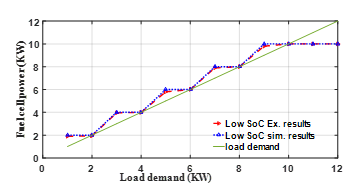 Figure 12: Real-time and Simulation Results at low SoC 50%
The results obtained from the simulation and experimental test are very closed to each other as shown in figures 10,11,12.
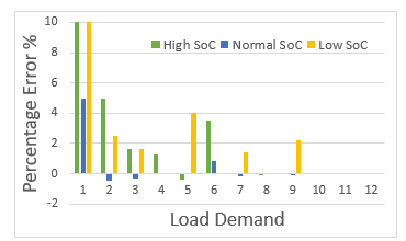 Figure 13: Percentage Error Between Simulation and Experimental Results
Comparing the values in table 2 and 3 the difference between the simulation results and the experimental results is the error which is very small and the maximum error about 10% at 1kW load demand that is because the chemical reaction in fuel cell takes times to produced power in the fuel cell starting. the difference between the simulation and experimental errors in the range between [-0.02,0.05] as shown in Figure 13.
11. Conclusions
This paper has developed the ship’s electric power system by using both the environmental friend power source to reduce greenhouse gas emissions and to introduce environment-friendly energy sources based on ANFIS technique that combined the benefit of neural network for training and fuzzy inference for creating a correlation between input and output to analysis, training, and deciding for solving optimization problems depending on previous knowledge to reduce the fuel consumption
The non-conventional problems for protection, transmission, and diagnostic in a ship’s electric power system take apriority to solve under Intelligent EMS and easy to interface with the ship’s integrated power system.
ANFIS EMS technique is a powerful and easy to adapt than conventional EMS when adding or remove any system or device in the ship power system. Intelligent EMS easy to apply to any system have the same profile with little adaptation.
Verifying the result obtained from the simulation with the results obtained from the real test found it’s the same gives more power to the system and this is the benefit of using intelligent system techniques.
This work is a part of past and future work that began with the designed hybrid energy management system, enhancement the system performance, and the user switched reluctance motor as propulsion motor. The future work is to use the simple and commercial embedded system “Raspberry Pi” as intelligent control and management for a hybrid ship power system.
Conflict of Interest
The authors declare no conflict of interest.
- K.M. Fameli, A.M. Kotrikla, C. Psanis, G. Biskos, A. Polydoropoulou, “Estimation of the emissions by transport in two port cities of the northeastern Mediterranean, Greece,” Environmental Pollution, 257, 113598, 2020, doi:https://doi.org/10.1016/j.envpol.2019.113598.
- M.H. Khooban, M. Gheisarnejad, H. Farsizadeh, A. Masoudian, J. Boudjadar, “A New Intelligent Hybrid Control Approach for DC–DC Converters in Zero-Emission Ferry Ships,” IEEE Transactions on Power Electronics, 35(6), 5832–5841, 2020, doi:10.1109/TPEL.2019.2951183.
- D. Chen, Y. Zhang, J. Lang, Ying Zhou, Y. Li, X. Guo, W. Wang, B. Liu, “Evaluation of different control measures in 2014 to mitigate the impact of ship emissions on air quality in the Pearl River Delta, China,” Atmospheric Environment, 216, 116911, 2019, doi:https://doi.org/10.1016/j.atmosenv.2019.116911.
- C. Wang, L. Hao, D. Ma, Y. Ding, L. Lv, M. Zhang, H. Wang, J. Tan, X. Wang, Y. Ge, “Analysis of ship emission characteristics under real-world conditions in China,” Ocean Engineering, 194, 106615, 2019, doi:https://doi.org/10.1016/j.oceaneng.2019.106615.
- D. Chen, X. Fu, X. Guo, J. Lang, Y. Zhou, Y. Li, B. Liu, W. Wang, “The impact of ship emissions on nitrogen and sulfur deposition in China,” Science of The Total Environment, 708, 134636, 2020, doi:https://doi.org/10.1016/j.scitotenv.2019.134636.
- C. Ghenai, I. Al-Ani, F. Khalifeh, T. Alamaari, A.K. Hamid, “Design of Solar PV/Fuel Cell/Diesel Generator Energy System for Dubai Ferry,” in 2019 Advances in Science and Engineering Technology International Conferences (ASET), 1–5, 2019, doi:10.1109/ICASET.2019.8714292.
- Y. Yuan, J. Wang, X. Yan, B. Shen, T. Long, “A review of multi-energy hybrid power system for ships,” Renewable and Sustainable Energy Reviews, 132, 110081, 2020, doi:https://doi.org/10.1016/j.rser.2020.110081.
- M. Gaber, S.H. El-banna, M. Eldabah, M.S. Hamad, “Model and Control of Naval Ship Power System by The Concept of All-Electric Ships Based on Renewable Energy,” in 2019 21st International Middle East Power Systems Conference (MEPCON), 1235–1240, 2019, doi:10.1109/MEPCON47431.2019.9007914.
- E. Eastlack, E. Faiss, R. Sauter, S. Klingenberg, M. Witt, S. Szymanski, A. Lidqvist, P. Olsson, “Zero Emission Super-Yacht,” in 2019 Fourteenth International Conference on Ecological Vehicles and Renewable Energies (EVER), 1–8, 2019, doi:10.1109/EVER.2019.8813677.
- S. Alhammadi, F. Al-Shami, A. Alhendi, O. Baobaid, A. Almaskary, A. Bouhraoua, “Autonomous Naval Surface Vehicle for Energy Generation in Open Seas,” in 2020 Advances in Science and Engineering Technology International Conferences (ASET), 1–4, 2020, doi:10.1109/ASET48392.2020.9118358.
- M. Gaber, S.H. El-banna, M.S. Hamad, M. Eldabah, “Performance Enhancement of Ship Hybrid Power System Using Photovoltaic Arrays,” in 2020 IEEE PES/IAS PowerAfrica, 1–5, 2020, doi:10.1109/PowerAfrica49420.2020.9219808.
- M. Gaber, S.H. El-banna, M.S. Hamad, M. Eldabah, “Studying the Effect of Using Multi-Phases Switched Reluctance Motor to Reduce the Torque Ripple for Ship Propulsion system,” in 2020 IEEE PES/IAS PowerAfrica, 1–5, 2020, doi:10.1109/PowerAfrica49420.2020.9219817.
- J. Prpić-Oršić, O.M. Faltinsen, M. Valcic, “Development strategies for greener shipping,” in Proceedings ELMAR-2014, 1–4, 2014, doi:10.1109/ELMAR.2014.6923321.
- A.J. Sorensen, R. Skjetne, T. Bo, M.R. Miyazaki, T.A. Johansen, I.B. Utne, E. Pedersen, “Toward Safer, Smarter, and Greener Ships: Using Hybrid Marine Power Plants,” IEEE Electrification Magazine, 5(3), 68–73, 2017, doi:10.1109/MELE.2017.2718861.
- P. Mertikas, S.E. Dallas, D. Spathis, T. Kourmpelis, I.P. Georgakopoulos, J.M. Prousalidis, D. V Lyridis, L. Nakos, P. Mitrou, V. Georgiou, “Furthering the Electricity to Ships and Ports: the ELEMED Project,” in 2018 XIII International Conference on Electrical Machines (ICEM), 2542–2548, 2018, doi:10.1109/ICELMACH.2018.8506729.
- N. Shakeri, M. Zadeh, J. Bremnes Nielsen, “Hydrogen Fuel Cells for Ship Electric Propulsion: Moving Toward Greener Ships,” IEEE Electrification Magazine, 8(2), 27–43, 2020, doi:10.1109/MELE.2020.2985484.
- W. Tang, R. Dickie, D. Roman, V. Robu, D. Flynn, “Optimisation of hybrid energy systems for maritime vessels,” The Journal of Engineering, 2019, 4516–4521, 2019, doi:10.1049/joe.2018.8232.
- O. Boutebba, A. Laudani, G.M. Lozito, F. Corti, A. Reatti, S. Semcheddine, “A Neural Adaptive Assisted Backstepping Controller for MPPT in Photovoltaic Applications,” in 2020 IEEE International Conference on Environment and Electrical Engineering and 2020 IEEE Industrial and Commercial Power Systems Europe (EEEIC / I CPS Europe), 1–6, 2020, doi:10.1109/EEEIC/ICPSEurope49358.2020.9160518.
- A. Luchetta, S. Manetti, M.C. Piccirilli, A. Reatti, F. Corti, M. Catelani, L. Ciani, M.K. Kazimierczuk, “MLMVNNN for Parameter Fault Detection in PWM DC–DC Converters and Its Applications for Buck and Boost DC–DC Converters,” IEEE Transactions on Instrumentation and Measurement, 68(2), 439–449, 2019, doi:10.1109/TIM.2018.2847978.
- X. Zhao, X. Zhang, “Artificial Intelligence Applications in Power System,” in Proceedings of the 2016 2nd International Conference on Artificial Intelligence and Industrial Engineering (AIIE 2016), Atlantis Press: 158–161, doi:https://doi.org/10.2991/aiie-16.2016.36.
- M.M. Saha, E. Rosolowski, J. Izykowski, “Artificial Intelligent Application to Power System Protection,” 2001.
- W. Huang, S. Liao, J. Teng, T. Hsieh, B. Lan, C. Chiang, “Intelligent control scheme for output efficiency improvement of parallel inverters,” in 2016 IEEE/ACIS 15th International Conference on Computer and Information Science (ICIS), 1–6, 2016, doi:10.1109/ICIS.2016.7550770.
- S. Njoya Motapon, L. Dessaint, K. Al-Haddad, “A Comparative Study of Energy Management Schemes for a Fuel-Cell Hybrid Emergency Power System of More-Electric Aircraft,” IEEE Transactions on Industrial Electronics, 61(3), 1320–1334, 2014, doi:10.1109/TIE.2013.2257152.
- P. Sanjeevikumar, B. Paily, M. Basu, M. Conlon, “Classification of fault analysis of HVDC systems using artificial neural network,” in 2014 49th International Universities Power Engineering Conference (UPEC), 1–5, 2014, doi:10.1109/UPEC.2014.6934775.
- W.R. Anis Ibrahim, M.M. Morcos, “Artificial intelligence and advanced mathematical tools for power quality applications: a survey,” IEEE Transactions on Power Delivery, 17(2), 668–673, 2002, doi:10.1109/61.997958.
- T.J. McCoy, “Electric Ships Past, Present, and Future [Technology Leaders],” IEEE Electrification Magazine, 3(2), 4–11, 2015, doi:10.1109/MELE.2015.2414291.
- M. Eremia, C.-C. Liu, A.-A. Edris, Artificial Intelligence and Computational Intelligence: A Challenge for Power System Engineers, IEEE: 721–729, 2016, doi:10.1002/9781119175391.ch14.
- P. García, C.A. García, L.M. Fernández, F. Llorens, F. Jurado, “ANFIS-Based Control of a Grid-Connected Hybrid System Integrating Renewable Energies, Hydrogen and Batteries,” IEEE Transactions on Industrial Informatics, 10(2), 1107–1117, 2014, doi:10.1109/TII.2013.2290069.
- D. V Lukichev, G.L. Demidova, A.Y. Kuzin, A. V Saushev, “Application of adaptive Neuro Fuzzy Inference System (ANFIS) controller in servodrive with multi-mass object,” in 2018 25th International Workshop on Electric Drives: Optimization in Control of Electric Drives (IWED), 1–6, 2018, doi:10.1109/IWED.2018.8321388.
- X. Jizhi, Z. Xin-yan, L. Jian-wei, “Application of Artificial Intelligence in the Field of Power Systems,” Journal of Electrical and Electronic Engineering, 7, 23, 2019.
- D. Nauck, A. Nürnberger, Neuro-fuzzy Systems: A Short Historical Review, 91–109, 2013, doi:10.1007/978-3-642-32378-2_7.
- D. Nauck, A. Nurnberger, “The evolution of neuro-fuzzy systems,” NAFIPS 2005 – 2005 Annual Meeting of the North American Fuzzy Information Processing Society, 98–103, 2005.
- S.N. Motapon, L. Dessaint, K. Al-Haddad, “A Robust $\hbox{H}_{2}$-Consumption-Minimization-Based Energy Management Strategy for a Fuel Cell Hybrid Emergency Power System of More Electric Aircraft,” IEEE Transactions on Industrial Electronics, 61(11), 6148–6156, 2014, doi:10.1109/TIE.2014.2308148.
- G. Yoon, K. Cho, L.W. Park, S.H. Lee, H. Chang, “Artificial Intelligence-Base d Energy Data Monitoring and Management System in Smart Energy City,” in 2020 IEEE International Conference on Consumer Electronics (ICCE), 1–2, 2020, doi:10.1109/ICCE46568.2020.9043110.
- G. Paganelli, S. Delprat, T.M. Guerra, J. Rimaux, J.J. Santin, “Equivalent consumption minimization strategy for parallel hybrid powertrains,” in Vehicular Technology Conference. IEEE 55th Vehicular Technology Conference. VTC Spring 2002 (Cat. No.02CH37367), 2076–2081 vol.4, 2002, doi:10.1109/VTC.2002.1002989.
- P. Rodatz, G. Paganelli, A. Sciarretta, L. Guzzella, “Optimal power management of an experimental fuel cell/supercapacitor-powered hybrid vehicle,” Control Engineering Practice, 13(1), 41–53, 2005, doi:https://doi.org/10.1016/j.conengprac.2003.12.016.
- J.P. Torreglosa, F. Jurado, P. García, L.M. Fernández, “Hybrid fuel cell and battery tramway control based on an equivalent consumption minimization strategy,” Control Engineering Practice, 19(10), 1182–1194, 2011, doi:https://doi.org/10.1016/j.conengprac.2011.06.008.
- P. García, J.P. Torreglosa, L.M. Fernández, F. Jurado, “Viability study of a FC-battery-SC tramway controlled by equivalent consumption minimization strategy,” International Journal of Hydrogen Energy, 37(11), 9368–9382, 2012, doi:https://doi.org/10.1016/j.ijhydene.2012.02.184.
- S. Mirjalili, A. Lewis, “The Whale Optimization Algorithm,” Advances in Engineering Software, 95, 51–67, 2016, doi:https://doi.org/10.1016/j.advengsoft.2016.01.008.
- P.A. Topan, M.N. Ramadan, G. Fathoni, A.I. Cahyadi, O. Wahyunggoro, “State of Charge (SOC) and State of Health (SOH) estimation on lithium polymer battery via Kalman filter,” in 2016 2nd International Conference on Science and Technology-Computer (ICST), 93–96, 2016, doi:10.1109/ICSTC.2016.7877354.
- D. Arcos-Aviles, J. Pascual, F. Guinjoan, L. Marroyo, G. García-Gutiérrez, R. Gordillo-Orquera, J. Llanos-Proaño, P. Sanchis, T.E. Motoasca, “An Energy Management System Design Using Fuzzy Logic Control: Smoothing the Grid Power Profile of a Residential Electro-Thermal Microgrid,” IEEE Access, 9, 25172–25188, 2021, doi:10.1109/ACCESS.2021.3056454.