
Variation of the Air-Fuel Ratio with Inlet Pressure, Temperature and Density
Volume 6, Issue 2, Page No 190-194, 2021
Author’s Name: Prosper Ndizihiwe1,a), Burnet Mkandawire2, Venant Kayibanda3
View Affiliations
1University of Rwanda, Renewable Energy, Kigali, Kigali, 4285, Rwanda
2University of Malawi, Mechanical Engineering, Lilongwe, Zomba, 278, Rwanda
3University of Rwanda, Electrical Engineering, Kigali, Kigali, 4285, Rwanda
a)Author to whom correspondence should be addressed. E-mail: ndizihiweprosper@gmail.com
Adv. Sci. Technol. Eng. Syst. J. 6(2), 190-194 (2021); ![]() DOI: 10.25046/aj060222
DOI: 10.25046/aj060222
Keywords: Air-fuel ratio, Combustion, Density, Pressure, Temperature

Export Citations
The control of the air-fuel ratio (AFR) is critical for the efficiency of the combustion. This is for achieving the better performance of the plant and result in high output energy. Computation of the AFR is gone considering the composition of the fuel regardless of the inlet pressure, density ad temperature of both fuel and the air. This paper models AFR as a function of the inlet temperature, density, and pressure. Formulated models have been checked using recorded data from the Jabana2 Oil Power Plant. The results show that the AFR increases by 1.5 units as the pressures of the gas increase by 0.6 bars but when it reaches 2.9 bar, AFR starts to decrease, 0.9% of the increase of the density leads to the decrease of the AFR of 0.4 in average. 3.5oC rise of inlet temperature lift the AFR by 0.2; however, it starts to decrease when the temperature reaches 78oC.
Received: 19 September 2020, Accepted: 11 February 2021, Published Online: 10 March 2021
1. Introduction
The combustion within the boiler burns fuel to create heat energy. The burning of fuel is the reaction of fuel with oxygen present in the air. The amount of fuel that can be burnt is limited by the quantity of oxygen [1]. Once all the fuel is not burnt at all, some of it stays in the boiler and other quantity goes into the atmosphere as flue gases [2]. This is the loss that causes small efficiency at some time abuses our environment [3]. It is therefore important to maintain AFR at optimum.
By definition, AFR is the fraction of air mass and the fuel mass. Different research like [4] and [5] among others, have been conducted considering the quantification of the air composition and the fuel composition. In [6], the author quantified these masses for complete combustion and also formulated the heating capacity based on the composition of the fuel. This is very important however other physical variables can alter the behavior of the AFR.
In [7], the author examined the role of variation of temperature inlet for lean air/fuel and designed the cylinder porous burner which absorbs the heat of combustion for a lean mixture of propane. They found that adjusting the flow rate of both air and propane gives high power output and efficiency when working at a normal temperature. This means that since the fuel is found at a different temperature, there is a need of knowing at which temperature is to be inserted, which affects also the density and pressure.
In [8]-[12], the researchers have all searched on the contribution of the temperature, the density, and the pressure and found that there are their influences on the combustion as well as the AFR, However, they didn’t estimate the how much they contribute. It is important to know how much any of its change varies the AFR at any kid of the fuel to achieve better combustion for efficient boiler performance.
In [13], the author found that the rich fuel in combustion leads to the formation of the thick porous zone which is one of the sources of the flame with exothermic chemical transformation. This is the cause of higher exhausts and therefore the fuel entry is to be managed.
These researchers demonstrated how the air-fuel ratio should be based on physical properties. However, on the field, the air-fuel ratio is calculated based on the composition of the fuel to be burned as regarded in these references among others [14]-[17].
In this research work, the AFR is modeled as a function of the inlet temperature of the fuel and the outlet density of the gases, then as a function of the pressure at the entry of the air.
Section 2, demonstrate the model of the AFR with the variation of the density and the temperature and validate it using experimental data from the field. In section 3, the author demonstrates the model of the AFR with the change of the pressure, and experimental results are presented. In section 4 there is a conclusion, recommendations as well as proposed for future work.
Nomenclature
(t): Internal energy, H ̇: Enthalpy
Q ̇(t): Heat Q_f : Heat transfer by radiation
Q_L : Heat transfer by furnace wall
LHV : The lower heating value of the fuel
m ̇_f: Fuel mass flow rate, m ̇_fb: Burned fuel mass flow rate
V_f: Furnace volume, ρ: Density, t_c: Combustion period
t_cmax: Maximum combustion period, r: Constant of the perfect gas
V: Volume, T: Temperature, M: Mass
P: Pressure, μ: Molecular mass
q_a: Airflow, q_(O_2 ): Oxygen flow
q_(N_2 ): Nitrogen flow, m_(O_2 ): A mixture of oxygen (%)
m_(N_2 ): A mixture of nitrogen (%)
Subscripts: c:coal/fuel, e:Exhausts
Consideration of the Density and the Temperature
The AFR is modeled by the quotient of the model of the air and fuel [18]. To do that let consider the entry and exit of the particles within the boiler and utilize the principle of energy and mass conservation. Analysis of the mass entry and exit in the furnace in Figure 1 helps for that analysis.
Model formulation
Figure 1 shows that the inputs which vary with time are the fuel and the air. The output is gas pressure. The general form of mass conservation stated by the law of thermodynamics [19], [20] says that under the assumption that there is no heat and mass transfer in the walls as well as a change in kinetic and potential energies during the flow.
 Figure 1: Entry and Exit of the furnace
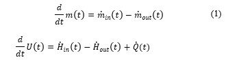
Considering or both energy and mass, we can have the following equations [21], :
 With the conservation of mass, this is the equation resulting from equation (1)
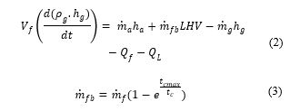
Equation (3) shows that maximum mass burned, (m_fb tends to m_f), if combustion period t_c tends to maximum combustion t_cmax.
Analysis of the data collected from the site
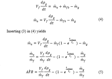
The model is to be validated by comparing measure values with computed using equation (5); doing that for different plants. Data from Jabana II Oil Thermal Power Plant have been used. The density of the gas and the temperature of the fuel at unlet have been used to compute the Air Fuel Ratio keeping all other parameters in equation (5) constant. V_f/m ̇_f which is the inverse of the density of the fuel at the beginning is kept to 2m3/kg, T_f=30^o C and τ close to T_f=23.
The results are shown in the figures.
 Figure 2: Variation of the Air Fuel Ratio and the Density of the Fuel
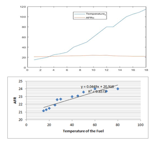 Figure 3: Variation of the Air Fuel Ratio with the temperature of the fuel
Figure 1 shows how the AFR is inversely proportional to the density and Figure 3 shows that the increase of the temperature would lead to the increase of the AFR, however, this change has a limit for both the density and the temperature.
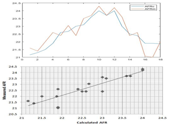 Figure 4: Comparison of measured and Calculated AFR
Figure 4 shows that values found by calculating by using the demonstrated equation (5) and the value of the AFR measured are close.
Consideration of the Pressure
Formulation of the model
This is based on the physical principle of conservation of momentum and mass variation of the pressure, proportional to the mass variation as stated in [20] assuming that the pressure in the furnace is equal to the atmospheric pressure.
Under an assumption that the internal pressure of the furnace is close to the atmospheric pressure i.e. case of perfect/ideal gasses).
The airflow q_a is the sum of the flow of the oxygen q_(O_2 )and the nitrogen q_(N_2 ):
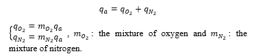
The quantity of the oxygen and nitrogen flow with time depends also on the percentage in the air; so
![]() On another hand, the coal or fuel flow in use consists of a mixture of carbon, hydrogen, sulfur, nitrogen, and oxygen (from water vapor) in different percentages. The combustion of each of the element of the air produces 〖CO〗_2, H_2 O, 〖SO〗_2, and 〖NO〗_2[21]. For the case of Oxygen, it is negative, since it is present in the air but it doesn’t undergo the combustion process.
On another hand, the coal or fuel flow in use consists of a mixture of carbon, hydrogen, sulfur, nitrogen, and oxygen (from water vapor) in different percentages. The combustion of each of the element of the air produces 〖CO〗_2, H_2 O, 〖SO〗_2, and 〖NO〗_2[21]. For the case of Oxygen, it is negative, since it is present in the air but it doesn’t undergo the combustion process.
This yields the following
![]()
Using the variation of total mass within the furnace by the fact that both air and the fuel enter but the exhaust q_e exit, the following expression will result.

The use of the data from the site/Jabana2 Oil Power Plants
Jabana 2 Oil Power plant is the fossil fuel energy source operating in Rwanda since 2009, producing 20MW of the power Owned by Rwanda Energy Group. It used Heavy Fuel Oil (HFO). At Jabana 2, HFO is pre-heated from 15C for achieving good viscosity. Its density is not controlled and the unlet air temperature is not changed from the ambient value. However, these values at the inlet aren’t controlled, their operation data show that they change the overall efficiency of the plant and the quantity of the exhausts.
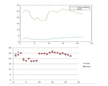 Figure 5: Variation of the Air Fuel Ratio with the pressure of the fuel
Figure 5 shows that the increase of the pressure and the temperature causes an increase in the air-fuel ratio but it starts to decrease when the pressure becomes higher.
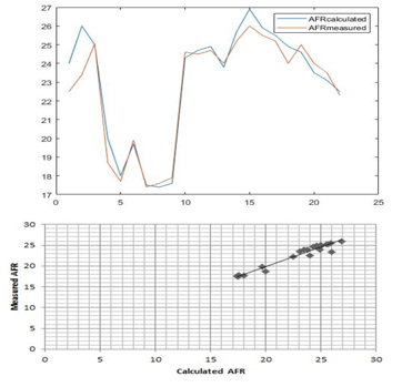 Figure 6: Comparison of Measured and Calculated AFR
Figure 6 shows that values found by calculating using the demonstrated equation (8) and the value of the AFR measured are close.
Conclusions
The increase of the temperature and reduction of the density of the air make the AFR high before it reaches the values at which it starts to reduce. Since the quantity of the fuel depends on how much energy is to be produced, the AFR is mainly altered by altering the quantity of the air. As the results show, this quantity of the air would be increased proportionally to the air temperature but when the temperature reaches 80C, the air is to be reduced as shown in Figure 3. About the pressure, it is visible from Figure 5 that from 3bar the air is to be increased within the burner but when arrived to 8bar, the quantity of the air is to be reduced for better combustion. For the case of the density, it is advantage to the AFR to have small density according to Figure 2, but if it continues to reduce up to 8kg/m2, the air should be reducing. These considerations are advantages in the sense that all the fuel will be burned without remaining air which contain nitrogen to form nitrite exhausts. The variation of the density, pressure, and temperature could be done to meet the AFR that has to be achieved. Besides harvesting more energy, this is important for minimizing environmental pollution as it reduces exhaust gases.
Conflict of Interest
The authors declare no conflict of interest.
Acknowledgment
The authors acknowledge the facilitation of Jabana 2 Oil Power plant to do experiment in the industry.
- R. Pradhan, P. Ramkumar, M. Sreenivasan, “Air-Fuel Ratio (Afr) Calculations In An Internal Combustion Engine Based On The Cylinder Pressure Measurements,” International Journal of Engineering Research and Application, 2(6), 1378–1385, 2012, doi:http://www.ijera.com/papers/Vol2_issue6/GW2613781385.pdf.
- J. Baranski, “Investigation of the Flow, Heat and Mass Transfer and Emissions in Pulverized Fuel Fired Boiler using Physical and Numerical Modeling,” International Journal of Energy for a Clean Environment, 11(5), 801–805, 2017, doi:10.1615/ICHMT.2006.TurbulHeatMassTransf.1760.
- B. Abbas Al-Himyari, A. Yasin, H. Gitano, “Review of Air-Fuel Ratio Prediction and Control Methods,” Asian Journal of Applied Sciences, 2(4), 471–478, 2014.
- A. Marjanovi, “Control of Thermal Power Plant Combustion Distribution Using Extremum Seeking,” in IEEE Transactions on Control Systems Technology, 1670–1682, 2017.
- A.H. Al-abbas, J. Naser, “CFD Modelling of Air-Fired and c firing propane,” in International Conference on Mechanical Engineering 2011, International Conference on Mechanical Engineering 2011, Bangladesh: 1–6, 2011.
- S. Mcallister, “Thermodynamics of Combustion,” Fundamentals of Combustion Processes, 1(4), 15–47, 2014, doi:10.1007/978-1-4419-7943-8_2.
- L.H.-V. Bubnovich Valeri, Pedro San Martin, “Electric power generation from combustion in porous media,” Journal of Porous Media, 19(10), 841–851, 2018, doi:10.1615/JPorMedia.v19.i10.10.
- D. You, Y. Huang, V. Yang, Combustion Science and Technology: A generalized model of acoustic response of turbulent premixed flame and its application to gas-turbine combustion instability analysis, Taylor & Francis, London, 2006, doi:10.1080/00102200590927012.
- B. Mendrea, J. Sterniak, “Effect of Ambient Temperature and Humidity on Combustion and Emissions of a Spark- Assisted Compression Ignition Engine,” Journal of Engineering for Gas Turbines and Power, 139(051501–1), 1–7, 2017, doi:10.1115/1.4034966.
- H.F. Alajmi, “Effect of Ambient Air Temperature on the Performance of Steam Generator,” International Journal of Environmental Science and Development, 8(7), 479–483, 2017, doi:10.18178/ijesd.2017.8.7.1000.
- L. Chao, L. Ke, W. Yongzhen, M. Zhitong, G. Yulie, “The Effect Analysis of Thermal Efficiency and Optimal Design for Boiler System,” Energy Procedia, 105, 3045–3050, 2017, doi:10.1016/j.egypro.2017.03.629.
- W.L. and G.Y. Geng Liang, Yan Bai and, “Optimization of an Industrial Steam Boiler System,” Measurement and Control -London- Institute of Measurement and Control, 43(4), 112–115, 2010.
- G.J. van Zyl, “Ballistic and combustion properties of high-pressure exponent hydrocarbon-based fuel-rich propellants,” International Journal of Energy for a Clean Environment, 5(1), 1048–1058, 2020, doi:10.1615/IntJEnergeticMaterialsChemProp.
- K.J.K.D.F. Adams, “the Air Fuel Ratio Study for the Mixture of Biogas and hydrogen on mild Combustion,” in: M.M. Noor, M. M. R. and J. I., ed., in International Journal of Automotive and Mechanical Engineering ·, Energy Procedia, New South Wales: 61–72, 2014, doi:10.1016/j.egypro.2011.02.151.
- S.A.S. Atnaw, Samson Mekbib, “Modeling and Simulation Study of Downdraft Gasifier Using Oil-Palm Fronds,” in ICEE 2009 3rd International Conference on Energy and Environment, International Conference on Energy and Environment, Malacca: 284–289, 2009.
- A. Guryanov, O. Evdokimov, S. Veretennikov, M. Guryanova, “Experimental investigation of premixed air – fuel mixtures and of the combustion specifics of diffusion fuel jets,” International Journal of Energy for a Clean Environment, 18(4), 335–348, 2017, doi:10.1615/InterJEnerCleanEnv.2018021223.
- B.R.D. K.J. As stroKm, “Drum-boiler dynamics,” Elsevier Science Ltd, 36(4), 363–378, 2000.
- A. Huber, W. Polifke, “Dynamics of practical premixed flames, part I: model structure and identification,” International Journal of Spray and Combustion Dynamics, Volume 1(3), 199–228, 2009.
- F.P. Ion V. Ion, “Dynamic model of a steam boiler furnace,” Thermal Systems and Environmental Engineering, 3(3), 22–26, 2019.
- A.O.S. R. G. Freire, J. M. Lemos, “Modelling the air/flue-gas circuit of a thermoelectric power plant unit,” Publicacoes, 2009.
- N. Mustafa llbas, Syred, “Influence of temperature, air:fuel ratio, geometry and fuel type on the nox emissions of small burners,” International Journal of Energy for a Clean Environment, 11(2), 30–38, 2002.