Closed Loop Capacitive Accelerometer Model using Simple Regression Test for Linearity

Adv. Sci. Technol. Eng. Syst. J. 6(2), 1038–1045 (2021);
 DOI: 10.25046/aj0602118
This article extends novelty of modeling capacitive accelerometer with PID controller to provide PI controller for better tuning and statistical test to determine the linear validation characteristics of closed capacitive accelerometer. Capacitive accelerometer is a sensor which uses the dynamic law of physics model Position-Velocity-Accelerator (PVA) by the movement of an electrode coupled to mass proof sandwich between parallel plates to detect vehicle/object displacement. The modelling of closed loop system helps to mitigate steady state error accumulation of measurements in open loop model. The accelerometer gives linear time dependence on output displacement after an input step-like function of acceleration. The closed model can predict the desired output signal. The linearity of the model is tested statistically using simple regression of 120 dataset. This shows a p-value of 2e-16 indicating that at any time, the acceleration predicts the displacement/position of vehicle/object.
1. Introduction
Accelerometer is a microelectromechanical sensor (MEMS) which is generally used in the measurement of moving body’s acceleration[1]. MEMS is widely used across the current settings of interconnected world in our daily lives [2]. The obtained acceleration is measured in gravity (g) [3]. The measurements of g can be transformed into velocity and position/displacement.
In the application of accelerometer, it provides a wide range of services in a lot of technologies aiding the prediction of most human and no-human activities. In [4], accelerometer is used on a bridge in Nottingham Wilford in the UK with the main purpose of determining the dynamic characteristics. This provided real-time information on suspended deck movement. It is applied using triaxial accelerometer and Real-time Kinematic Global position system (RTK-GPS). The inclusion of the RTK-GPS is applied to measure the low-frequency vibrations of medium span suspension bridge. The reason for this inclusion is to aid the accelerometer which measures based on high-frequency rate. Similar bridge technique is used but in this domain it is applied in bridge management system and land safety [5]. The only component which changed is the replacement of RTK-GPS with three Leica-GPS.
In the determination of human kinematics, accelerometer places an exceptional role as well. According to [6], the authors presented triaxial accelerometer with a specific value of CDXL04M3 is applied in the recognition of classification of problem during people activities. Also in [7], the article provides a description in the development real-time classification persons activities such as: walking, standing and running using wearable device. The only differentiation this application is the system composition where a two-accelerometer (ADXL202JE) layer model that integrates multiple component Gaussian mixture model with Markov models is applied. This is to accurately classify the zone of user state.
Accelerometer application in human context [8, 9] applied triaxial accelerometer (ActiGraph GT3X+) to validate the process of determining everyday human physical activities. The device is placed at the thigh and hip to identify: cycling, walking, climbing of stairs, running, sitting, and no movements. In [10], authors worked on the determination and understanding of physical activities and key behavioral changes among children. This led to the implemented four different accelerometers namely: ActiGraph, Actical, Actiwatch, and RT3 Triaxial devices. This produces a regression model. According to [11] and [12], triaxial accelerometer and Wireless Wearable Multisensory Integrated Measurement System (WIMS) were implemented together to measure activities such as human heartbeats, hip motion, and other sensors. Additionally, in[13], the author developed a wearable wireless base displacement system which utilizes inertial measurement unit (IMU) having triaxial accelerometer onboard. This system monitors the daily indoor activities of humans in buildings such as health statuses and locations.
In other applications such as vehicular domain, the triaxial has received enormous integrated application. Especially, the use of tracking of vehicle velocity and position coupled with other MEMS sensors [14].
There is another form of accelerometer called uniaxial or single axial which used in predicting the behavior of person in motion [15]-[20]. In [19], the authors presented ideas of applying 2 to 3 uniaxial sensors mounted on human body for behavioral investigations. All uniaxial accelerometers were in 2-dimensions. According to [20], the author comparison between uniaxial and triaxial accelerometer application in human activities, showed no difference in the results obtained.
However, in this paper the research design looks at the implementation of the triaxial accelerometer since it is in a 3D form associated in measuring X, Y and Z of the acceleration of vehicle dynamics.
Velocity and position are computed mathematically from acceleration. The position represents the displacement from the mechanical model. This displacement measurement very small. To achieve a better measurement, and electronic readout unit is attached. There are various types of mechanical models. These include: capacitive [21]-[31], piezo-resistive [32], and thermal [33], [34].
The choice of capacitive accelerometer in vehicle tracking is mainly based on its advantages such as:
- Zero static biasing with high sensitivity ability, and better thermal stability. According to [35], these characteristics make capacitive accelerometer model preferred to others.
- It has the edge over other due to size, less expensive, and more flexible in interfacing with other circuitry [36].
- Low temperature and better linearity[37]
However, the capacitive accelerometer has the challenge of high capacitance variation sometimes due the type of mass proof, low damping factor, high sensitivity providing higher resolution that give higher frequencies [38].
A triaxial capacitive accelerometer IC module is integrated with GPS module used in determining vehicle position. The integrations provides a uniform sensitivity which is distributed in the 3D of the vehicle position in the x-y-z domain. [39], [40]. The accelerometer used is made up of glass-silicon which serves as a mass proof. This glass is suspended to the chassis of the vehicle with four locks [41]. This detects parallel motion in z-acceleration and measurements are made in X or Y axis acceleration during tilting of the proof mass. Displacement is detected when electrodes connected to the mass proof which is then sandwich between parallel plates. By this mechanism, the acceleration is measured in the X, Y, and Z axis [9], [3].
It is based on this that the velocity and position cand be obtained using Position-Velocity-Acceleration (PVA) model which Obeys Newton’s law of physical object in motion and that of Hooke’s law [31]. the principle underlining PVA is the first and second integral of acceleration model to produce velocity and position respectively [42]. Therefore, for any measurements of acceleration should provide a proportional outputs of velocity and position of a body in motion with an accelerometer [40], [43], [44].
This article looks at modelling the linear characteristics of capacitive accelerometer using PI-controller to determine the linear dependence relationship between acceleration and position. It also verifies the model for statistical significance using simple regression model. The model is based on mathematical modelling simulations using MATLAB/Simulink.
2. Method of analysis
The method of design is by mathematical modelling of system dynamics of a moving mass proof using law of physics. Figure 1 shows an eight stage methodological view of analyzing and simulating of the capacitive accelerometer.
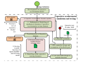
Figure 1: Methodological view of modelling a capacitive accelerometer
- Sensing dynamics: is the model for the change in capacitance during the movement of object (vehicle) [30].
- Model for capacitive sensing dynamics: is the model for the change in capacitance during the movement of object (vehicle) [30].
- Develop transfer function of signal amplifier-inverting model: the output from 4 is amplified using OpAmp and inverted to obtain the original signal. These are all handled in frequency domain for easy computation.
- Low pass filter transfer function: this filters high frequency measurements associated with acceleration measurements. LPF will allow only the low frequency for better measurements of position variables.
- PI controller design and assumption of feedback gain: this stage is done by developing a controller gain matrix and a feedback gain.
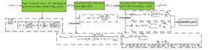
Figure 2: open loop accelerometer system with readout components[50].
- Results validation: to validate the results from the model, data collected is tested using simple regression model for input to output linear dependency using the P-value as a criteria of validity.
3. Open loop accelerometer system
The linear time variant (LTV) model of the mechanical model consisting of mass, damper and spring is represented in (1) [45]-[48]:
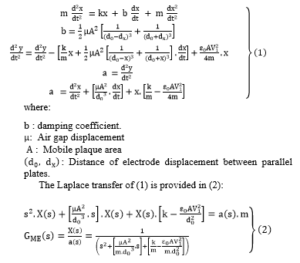
: Gain of Mechanical module
In figure 2, block diagrams of various units of the accelerometer and their models for open loop system is represented. the diagram has the mechanical unit, electronic readout circuit which consist of gain detection the demodulation unit with low pass filter (LPF) [19], [45]-[47], [49].
The following represent key nomenclature in Figure 2:
: Gain Detection
: signal Detection unit
: Demodulation and LPF Gain
: Electronic Read-out Operational Amplifier Gain
: Electronic Read-out inverter Gain
: Electronic Read-out Low Pass Filter Gain
: output displacement of
Accelerometer detection block is the block which electronically detects the displacement of the mass proof with a rod to dangle between the parallel plate. This unit produces a gain, . This gain consists of the electrostatic force of parallel plate and the operational amplifier. The operational amplifier helps boast the electrical signal detected from the mechanical displacement for processing [34].
in Figure 2 is passed through a Accelerometer Demodulation unit to produce .
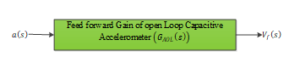
Figure 3: The open loop gain block diagram
Figure 3 represents overall open loo transfer function, which consists of the cascade of

The open loop of the capacitive accelerometer in (5) is now simplified into two main function blocks, thus the mechanical unit and the electronic readout unit in Figure 4.
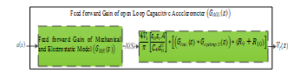
Figure 4: Mechanical and electronic readout of accelerometer
The modeling of the two blocks is represented in (6):
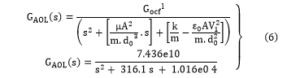
The modeling of (6) into a closed loop form is discussed in the next section using Proportional-Integral (PI) controller.
4. Closed loop accelerometer modeling
The design of a closed loop accelerometer is considered in this section by designing the feedback and control gain matrices of PI controller models.
4.1. Designing of feedback model
Feedback model is designed to help compare the acceleration (reference signal) to the position (output signal). Base on the feedback a suitable controller can be tuned to achieve a desirable output.
4.2. Choosing Feedback signal
According to [51], feedback model is based the type of sensor which provides a proportional signal to the dynamic model (mechanical unit). Therefore, in choosing the feedback signal, a balancing force is needed to check the inertial forces mechanical unit of the accelerometer. This balancing force is called the electrostatic force. It is chosen because it establishes the reading of small displacement from the proof mass between the two fixed electrodes in parallel plates[23]. The electrostatic force is used to provide restoration of sensing force to balance acceleration force. Figure 5 shows the representation of the accelerometer closed loop structure.

Figure 5: closed loop structure of accelerometer
A bias signal is introduced with excitation signal to obtain a feedback signal to the two electrodes. This generates the and as negative electrode and positive electrode supplies respectively. This is represented in (7) as:
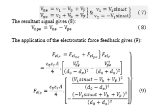
The accelerometer having high system frequency and considering the initial position of the proof mass, the electrostatic force feedback mean signal is represented mathematically in (10):
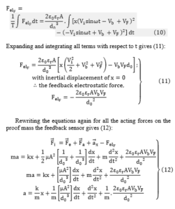
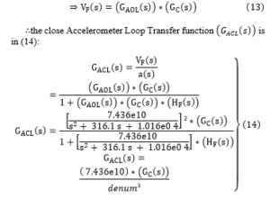
∴the close Accelerometer Loop Transfer function is in (14):
5. Closed loop accelerometer simulation and results
5.1. Open loop accelerometer model and characteristics
The open loop model of accelerometer is represented by the mechanical-charge detection model and the electronic demodulator model in Figure 6 and 7, respectively.
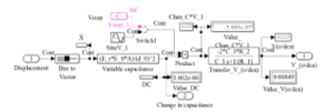
Figure 6: Acceleration Charge Detection unit
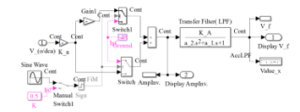
Figure 7: Demodulator Electronic processor
The mechanical, charge detection, and electronic demodulator transfer function is given in (15):
![]()
The open loop characteristics are shown in Figure 8 is based on Figure 6 and 7. For an input acceleration of the model provides Mechanical displacement response of and the respective charge detection unit and low pass filter output is displayed as well.
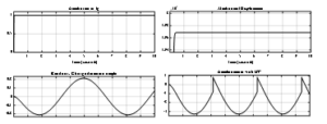
Figure 8: open loop characteristics of accelerometer model.
The overall transfer function of the open loop model in (15) produces an overshoot of about with an input-output response rise time of as shown in Figure 9.
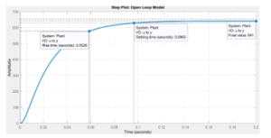
Figure 9: overall open loop transfer function characteristics of accelerometer model.
In Figure 10, the open loop bode plot shows system gain of 56.1 dB which was constant until it reached a frequency response is 791 rad/s .
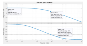
Figure 10: the magnitude and phase of the open loop accelerometer transfer function against angular frequency.
The open loop gain gives the open loop minimum stability margins at and frequency .
For the phase, at low frequency, the phase is and at high frequency is . The minimum stability margins are against frequency of .
5.2. Accelerometer closed loop model and characteristics
This section looks at the modelling of the close system of the accelerometer. The system uses proportional integral (PI) controller to establish the stability of the open loop gain. The gain of the controller is represented in (16):
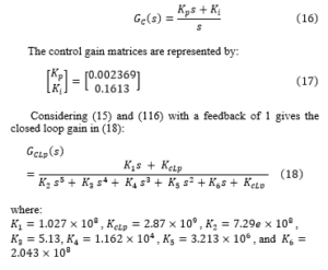
The overall closed loop transfer function gain in (18) is represented in Figure 11.
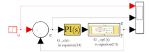
Figure 11: closed loop accelerometer model in MATLAB/SIMULINK.
In Figure 12, the response time is at amplitude of with an overshoot of 10.4% at and an amplitude of the model shows a settling in at .
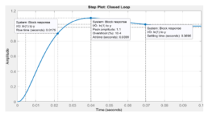
Figure 12: Closed loop accelerometer characteristics with PI controller.
Figure 13 represents the Bode plot for closed loop gain which gives a minimum stability margin at and .

Figure 13: Bode plot for closed loop accelerometer.
The minimum stability margins are against frequency of having a delay margin of .
6. Statistical Test on Accelerometer Linearity
In this section, a linearity test is applied on the acceleration model. The test uses simple regression and p-value to establish linearity of the model.
A simple regression model is developed for the accelerometer model using the algorithm in (19):
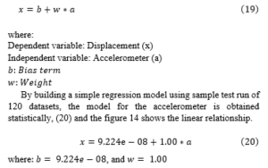
where , and
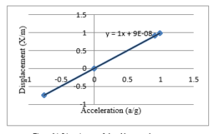
Figure 14: Linearity test of closed loop accelerometer.
In Figure 14, it is shown that the acceleration and the displacement are linearly dependent. The statistical test of p-value is below 0.05. The model’s p-value is , which means the acceleration can predict the displacement.
7. Conclusion
This paper looks at the modelling and simulation of closed loop capacitive accelerometer. The model applied is the Position-Velocity-Acceleration (PVA) which consist of mechanical unit, charge detection unit, and signal demodulator with filter unit.
The results from the open loop after applying acceleration of shows an overshoot to an amplitude of . However, the by controlling the accelerometer in in a closed loop form with a Proportional-Integral (PI) control gain, the desirable output is obtained.
The linearity of the model is with simple regression which shows it is predictable with a statistical significance of as its p-value. However, for better optimization, the accelerometer model must be modelled in a state space domain using Gaussian stochastic model where noise is factored as independent of system memory. This would also provide a better technique for better prediction of position. In another vein, future model can consider temperature as a component of damping coefficient .
Conflict of Interest
The authors of this manuscript have seen and agree with the contents. We declare that this work is the original work submitted for publication and has undergone peer review process in no other journal other than this.
- S. Yan, H. Liu, Q. Xu, D. Liu, M. Zhang, W. Wu, L. Tu, “A method for improving out-of-plane robustness of an area-changed capacitive displacement transducer used in a micro-accelerometer,” Sensors and Actuators, A: Physical, 312(May), 112156, 2020, doi:10.1016/j.sna.2020.112156.
- G. Lammel, “The future of MEMS sensors in our connected world,” Proceedings of the IEEE International Conference on Micro Electro Mechanical Systems (MEMS), 2015-Febru(February), 61–64, 2015, doi:10.1109/MEMSYS.2015.7050886.
- M. Devi, B.A. Kumar, M.T. Scholar, “Accelerometer Based Direction Controlled Wheelchair Using Gesture Technology,” 1070(3), 1065–1070, 2014.
- M. Meo, G. Zumpano, X. Meng, E. Cosser, G. Roberts, A. Dodson, “Mechanical Systems and Signal Processing Measurements of dynamic properties of a medium span suspension bridge by using the wavelet transforms,” Mechanical Systems and Signal Processing, 20, 1112–1133, 2006, doi:10.1016/j.ymssp.2004.09.008.
- X. Meng, Real-time Deformation Monitoring of Bridges Using GPS/Accelerometers, Jul. 2020.
- N. Ravi, N. Dandekar, P. Mysore, M.L. Littman, “Activity recognition from accelerometer data,” in Proceedings of the National Conference on Artificial Intelligence, 1541–1546, 2005.
- R.W. DeVaul, S. Dunn, “Real-time motion classification for wearable computing applications,” 2001, Project Paper, Http://Www. Media. Mit. Edu/Wearables/Mithril/Realtime. Pdf, 1–14, 2001.
- M. Korshøj, J. Kristiansen, C. Hanisch, A. Holtermann, E.U.K. Online, “Key findings,” Article in Journal of Physical Activity and Health, (May), 2035, 2010, doi:10.1016/0267-3649(88)90030-1.
- M. Korshøj, J. Kristiansen, C. Hanisch, A. Holtermann, “Detection of Physical Activity Types Using Triaxial Accelerometers,” Article in Journal of Physical Activity and Health, 2012, doi:10.1123/jpah.2011-0347.
- P. Freedson, D. Pober, K.F. Janz, “Calibration of Accelerometer Output for Children,” Med. Sci. Sports Exerc, 37(11), 523–530, 2005, doi:10.1249/01.mss.0000185658.28284.ba.
- S.S.M.E. Assistant, B. Birosekhan, G. Chandru, K. Naveen, K. Praveen, “Predicting Human Activities Using Accelerometer And Sensors,” 3(1), 3743–3747, 2014.
- D. Dissertation, LOW-POWER FRONT-ENDS FOR CAPACITIVE THREE-AXIS ACCELEROMETERS Doctoral Dissertation, 2010.
- M. Menai, V.T. Van Hees, A. Elbaz, M. Kivimaki, A. Singh-Manoux, S. Sabia, “Accelerometer assessed moderate-To-vigorous physical activity and successful ageing: Results from the Whitehall II study,” Scientific Reports, 8, 2017, doi:10.1038/srep45772.
- J.P. Merepala, “Tri-axis MEMS Accelerometer for Vehicle Accident Monitoring,” 1068–1070, 2016.
- P.H. Veltink, H.B.J. Bussmann, W. De Vries, W.L.J. Martens, R.C. Van Lummel, “Detection of static and dynamic activities using uniaxial accelerometers,” IEEE Transactions on Rehabilitation Engineering, 4(4), 375–385, 1996, doi:10.1109/86.547939.
- F. Bagalá, V.L. Fuschillo, L. Chiari, A. Cappello, “Calibrated 2D angular kinematics by single-axis accelerometers: From inverted pendulum to N-Link chain,” IEEE Sensors Journal, 12(3), 479–486, 2012, doi:10.1109/JSEN.2011.2107897.
- J.C. Eisenmann, S.J. Strath, D. Shadrick, P. Rigsby, N. Hirsch, L. Jacobson, “Validity of uniaxial accelerometry during activities of daily living in children,” European Journal of Applied Physiology, 91(2–3), 259–263, 2004, doi:10.1007/s00421-003-0983-3.
- N. Ruch, M. Rumo, U. Mäder, “Recognition of activities in children by two uniaxial accelerometers in free-living conditions,” European Journal of Applied Physiology, 111(8), 1917–1927, 2011, doi:10.1007/s00421-011-1828-0.
- S. Toumodge, “Book reviews – Modern control systems,” IEEE Control Systems Magazine, 6(5), 56–56, 1986, doi:10.1109/MCS.1986.1105138.
- L.A. Kelly, D. Ge Mcmillan, A. Anderson, M. Fippinger, G. Fillerup, J. Rider, Validity of actigraphs uniaxial and triaxial accelerometers for assessment of physical activity in adults in laboratory conditions, 2013.
- Y. Matsumoto, M. Esashi, “Integrated silicon capacitive accelerometer with PLL servo technique,” Sensors and Actuators: A. Physical, 39(3), 209–217, 1993, doi:10.1016/0924-4247(93)80221-2.
- W. Kuehnel, S. Sherman, “A surface micromachined silicon accelerometer with on-chip detection circuitry,” Sensors and Actuators: A. Physical, 45(1), 7–16, 1994, doi:10.1016/0924-4247(94)00815-9.
- B.E. Boser, R.T. Howe, “urf ace Micromachined Accelerometers,” 31(3), 1996.
- C. Hierold, A. Hildebrandt, U. Näher, T. Scheiter, B. Mensching, M. Steger, R. Tielert, “A pure CMOS surface-micromachined integrated accelerometer,” Sensors and Actuators, A: Physical, 57(2), 111–116, 1996, doi:10.1016/S0924-4247(97)80101-X.
- N. Yazdi, K. Najafi, “An All-Silicon Single-Wafer Micro-g Accelerometer Process,” Journal of Microelectromechanical Systems, Vol. 9, 9(4), 544–550, 2000.
- H. Luo, G. Zhang, L.R. Carley, G.K. Fedder, “A post-CMOS micromachined lateral accelerometer,” Journal of Microelectromechanical Systems, 11(3), 188–195, 2002, doi:10.1109/JMEMS.2002.1007397.
- B.V. Amini, F. Ayazi, “A 2.5-V 14-bit ∑Δ CMOS SOI capacitive accelerometer,” IEEE Journal of Solid-State Circuits, 39(12), 2467–2476, 2004, doi:10.1109/JSSC.2004.837025.
- P.L. Walter, “The history of the accelerometer,” S V Sound and Vibration, 31(3), 16–22, 1997.
- L.M. Roylance, J.B. Angell, “A batch-fabricated silicon accelerometer,” IEEE Transactions on Electron Devices, 26(12), 1911–1917, 1979, doi:10.1109/T-ED.1979.19795.
- H. V. Allen, S.C. Terry, D.W. De Bruin, “Accelerometer systems with self-testable features,” Sensors and Actuators, 20(1–2), 153–161, 1989, doi:10.1016/0250-6874(89)87113-6.
- K. Yamada, K. Higuchi, H. Tanigawa, “A novel silicon accelerometer with a surrounding mass structure,” Sensors and Actuators: A. Physical, 21(1–3), 308–311, 1990, doi:10.1016/0924-4247(90)85061-8.
- C. Song, B. Ha, S. Lee, “Micromachined inertial sensors,” IEEE International Conference on Intelligent Robots and Systems, 2(8), 1049–1056, 1999, doi:10.1109/iros.1999.812819.
- R. Hiratsuka, D.C. van Duyn, T. Otaredian, P. de Vries, P.M. Sarro, “Design considerations for the thermal accelerometer,” Sensors and Actuators: A. Physical, 32(1–3), 380–385, 1992, doi:10.1016/0924-4247(92)80016-V.
- A.M. Leung, J. Jones, E. Czyzewska, J. Chen, B. Woods, “Micromachined accelerometer based on convection heat transfer,” Proceedings of the IEEE Micro Electro Mechanical Systems (MEMS), 627–630, 1998, doi:10.1109/memsys.1998.659830.
- A. Kazama, T. Aono, R. Okada, “Stress relaxation mechanism with a ring-shaped beam for a piezoresistive three-axis accelerometer,” Journal of Microelectromechanical Systems, 22(2), 386–394, 2013, doi:10.1109/JMEMS.2012.2227139.
- J. Chae, H. Kulah, K. Najafi, “An in-plane high-sensitivity, low-noise micro-g silicon accelerometer with CMOS readout circuitry,” Journal of Microelectromechanical Systems, 13(4), 628–635, 2004, doi:10.1109/JMEMS.2004.832653.
- B. Li, D. Lu, W. Wang, “Micromachined accelerometer with area-changed capacitance,” Mechatronics, 11(7), 811–819, 2001, doi:10.1016/S0957-4158(00)00050-7.
- K. Najafi, A. Selvakumar, K. Najafi, J. Bernstein, A. Arbor, P. Examiner, H. Williams, P.C. Kushman, “United States Patent ( 19 ),” (19), 2000.
- T. Mineta, S. Kobayashi, Y. Watanabe, S. Kanauchi, I. Nakagawa, E. Suganuma, M. Esashi, “Three-axis capacitive accelerometer with uniform axial sensitivities,” Journal of Micromechanics and Microengineering, 6(4), 431–435, 1996, doi:10.1088/0960-1317/6/4/010.
- T. Lehtonen, J. Thurau, “Monolithic Accelerometer for 3D Measurements,” Advanced Microsystems for Automotive Applications 2004, 11–22, 2007, doi:10.1007/978-3-540-76989-7_2.
- V. Josselin, P. Touboul, R. Kielbasa, “Capacitive detection scheme for space accelerometers applications,” Sensors and Actuators, A: Physical, 78(2), 92–98, 1999, doi:10.1016/S0924-4247(99)00227-7.
- M. Youssef, M.A. Yosef, M. El-Derini, “GAC: Energy-efficient hybrid GPS-accelerometer-compass GSM localization,” GLOBECOM – IEEE Global Telecommunications Conference, 2010, doi:10.1109/GLOCOM.2010.5684304.
- A.M. Dinarvand, N. Dinarvand, M. Khaleqi, Q. Joogh, “Current Trends in Technology and Science Behavioral Modeling and Simulation of an Open-loop MEMS Capacitive Accelerometer with the MATLAB/SIMULINK,” 2014.
- B. Guldimann, P. Dubois, P.A. Clerc, N. De Rooij, “Transducers ’01 Eurosensors XV,” Transducers ’01 Eurosensors XV, (April), 2001, doi:10.1007/978-3-642-59497-7.
- P. Chen, J. Bai, S. Lou, Q. Lu, D. Han, X. Jiao, “Design of the closed-loop capacitive microaccelerometer based on PSpice,” 1st International Conference on Electronics Instrumentation and Information Systems, EIIS 2017, 2018-Janua, 1–4, 2018, doi:10.1109/EIIS.2017.8298762.
- K.N. Khamil, K.S. Leong, N. Bin Mohamad, N. Soin, “Analysis of MEMS Accelerometer for Optimized Sensitivity,” International Journal of Engineering and Technology, 6(6), 2705–2711, 2014.
- M. Kraft, C.P. Lewis, T.G. Hesketh, “Control System Design Study for a Micromachined Accelerometer,” IFAC Proceedings Volumes, 30(21), 139–143, 1997, doi:10.1016/s1474-6670(17)41429-7.
- Y. Terzioglu, S.E. Alper, K. Azgin, T. Akin, “A capacitive MEMS accelerometer readout with concurrent detection and feedback using discrete components,” Record – IEEE PLANS, Position Location and Navigation Symposium, 12–15, 2014, doi:10.1109/PLANS.2014.6851351.
- Y. Chu, J. Dong, B. Chi, Y. Liu, “A novel digital closed loop MEMS accelerometer utilizing a charge pump,” Sensors (Switzerland), 16(3), 1–11, 2016, doi:10.3390/s16030389.
- M. Hamidu, J.J. Kponyo, A. Acakpovi, “Innovative prediction of vehicle position based on closed loop modeling of capacitive accelerometer,” in Proceedings – 2019 International Conference on Cyber Security and Internet of Things, ICSIoT 2019, 54–61, 2019, doi:10.1109/ICSIoT47925.2019.00017.
- P.H. Zipfel, Modeling and Simulation of Aerospace Vehicle Dynamics, Second Edition, 2007, doi:10.2514/4.862182.