
Observer-Based Method of Feature Extraction for the Fault Detection of Permanent Magnet Synchronous Motors
Volume 6, Issue 2, Page No 942-948, 2021
Author’s Name: Hoang Giang Vua), Thi Thuong Huyen Ma
View Affiliations
Faculty of Electrical engineering, Electric Power University, Hanoi, 100000, Vietnam
a)Author to whom correspondence should be addressed. E-mail: giangvh@epu.edu.vn
Adv. Sci. Technol. Eng. Syst. J. 6(2), 942-948 (2021); ![]() DOI: 10.25046/aj0602107
DOI: 10.25046/aj0602107
Keywords: Fault detection, Feature extraction, Observer, Permanent magnet synchronous motors

Export Citations
This paper presents a new observer-based method which deals with the extraction of amplitude of characteristic frequencies for the fault diagnosis in permanent magnet synchronous motors (PMSM). First, a pilot survey is made to investigate the typical harmonics in the line currents of PMSM. Second, an appropriate structure of observer is formulated with the input of current signature in the time domain. By transforming into the Laplace domain, the convergence of the observer is proven. Using the proposed observer, a feature extraction method for fault detection can be introduced; in which the Park’s vector module (PVM) of the line currents is selected as the signature for the feature extraction of the amplitude at the second order harmonic. Simulation and experiment of the PMSM operating in speed control mode are carried out to provide the line current data for analysis. The results show that the amplitude of second order harmonic can be calculated and on-line monitored that demonstrates the effectiveness of the proposed method.
Received: 02 October 2020, Accepted: 30 January 2021, Published Online: 10 April 2021
1. Introduction
The permanent magnet synchronous motors have been widely used in various industrial applications due to several advantages, including small size, light weight, and simple structure. Regarding the operation variables, these motors are known with prominent features of high efficiency, high power and torque density. Therefore, they are usually preferred selection in various home and industrial applications, such as electric vehicles, manufacturing systems, full-rated converter-based wind power systems and so on [1].
During the service, the motor suffers from electrical, mechanical and thermal stresses that several faults, including the electrical, mechanical and magnetic faults, may occur. Stator inter-turn short circuit is considered as the most common fault in permanent magnet synchronous motors (PMSM) with about 31% of all failures [2]. The inherent aggressive growth and self-intensifying feature of the inter-turn fault in the stator lead to more faulty turns, phase-to-phase and phase-to-ground fault or can demagnetize permanent magnets irreversibly [1]. Consequently, the motor performance is seriously affected in the breakdown duration. Hence, it is essential to adopt a timely and precise diagnosis method in order to quickly detect the faults in PMSM system and have the warning signal to operators.
The literature review shows that diagnostic techniques for machines can be divided into three groups: model-based fault diagnosis methods, signal-based fault diagnosis methods and data-driven intelligent diagnosis methods [1], [3]. The fault diagnosis methods of the PMSM have been primarily built on the basis of the knowledge of machine model or signals. The model-based techniques are used to detect the fault by monitoring the difference between the measured output and model output to determine the fault type. Electrical equivalent circuit (EEC) models, magnetic equivalent circuit (MEC) models and finite element model (FEM) are commonly used to identify the inter-turn short circuit, eccentricity and demagnetization faults. However, the effectiveness of this method depends on the accuracy of the machine model. Meanwhile, in the signal-based methods, the measured signals are extracted to obtain the faulty feature in order to issue diagnosis decision. The feature can be extracted in frequency domain, time-frequency domain, wavelet domain or in the form of statistical one [1], [4]. The classical method carried out in frequency domain was fast Fourier transform (FFT) where the characteristic frequency could be clearly shown in the spectrum of the faulty signatures [4]. The FFT was extended to Short-time Fourier transform (STFT), which was implemented with time-frequency analysis in order to keep the time information [5]. The signal was divided into small time windows to provide a high resolution. This method allows dealing with nonlinear complex signal. However, the disadvantage of this STFT is the time and frequency resolution does not accurate at the same time, therefore it requires a high computation cost in order to get great resolution. This drawback is overcome by using Hilbert-Huang transform (HHT) method. Based on Hilbert-Huang transform, a signal processing in time-frequency domain could be achieved and implemented in transient conditions [2], [6]. To deal with the problem of false alarm in transient conditions, the wavelet-based technique was another favorite choice to be applied in the diagnosis systems [7]. In company with the development of artificial intelligence and machine learning, many data-driven intelligent diagnosis algorithms have been suggested recently to identify PMSM faults. Deep learning and support vector machine have been interested by many researchers because of their high intelligence. But the drawback of high requirements for hardware and long processing time limit the application of data-driven intelligent diagnosis method [1].
In the case of stator inter-turn short circuit, several methods that are classified by the applied signals, such as the current, voltage, torque, flux, electric and magnetic parameters, have been introduced [8]. Because the appearance of the inter-turn short circuit modifies the spectra of the current, the fault can be recognized. Once the fault occurs, the magnetic field distribution in the motor will vary. Therefore, there will be an increase in the amplitude of high-order harmonics or the appearance of new inter-harmonics. It is noted that, the harmonics in the line current are not only due to the imperfect sinusoidal flux distribution, the dead time of converter and the offset of sensor [9] but also the occurrence of inter-turn short-circuit faults in the machine [10]. The most common technique in the fault diagnosis, which always comes first in the selection for the fault diagnosis in both steady state and transient conditions, is based on the machine current signature analysis (MCSA).
In what follows, the indexes that are applied in the steady state operation of PMSMs will be synthesized.
Spectral analysis of magnetic field signal in the air gap shows that the inter-turn short-circuit faults cause an increase in the amplitude of sideband components at the different frequencies (fB) as calculated in (1) [11]:
![]()
where k = 1,3,5,…; P is the number of poles; and f1 is the fundamental frequency.
Consequently, the spectrum of other motor state variables such as current, torque, and speed will include some interest frequencies. In case the supplied voltage is sinusoidal, the frequency pattern in the current due to inter-turn short circuit (fi) is presented as [8], [11], [12]:
![]()
where n = 1,3,5,…; k = 1,2,3,…
Thus, the amplitude of this harmonic is a good indicator for fault diagnosis. The third-order harmonic of the negative frequency in the line current of permanent magnet brushless DC motor’s (BLDC motor) was reported and used as the fault index since it is independent from the imbalance of supplied source and operating conditions. However, the drawback of this method is inefficient in low speed or light load [13]-[15]. Moreover, the inter-turn fault also causes the third-order harmonic in the line current [2].
Monitoring the amplitude of the second-order harmonics in both current and voltage also allows detecting the inter-turn short-circuit fault. In [8], the Park’s vector is transformed from three phase line currents; and its module is extracted to obtain the amplitude at 2f1 (two times of the fundamental frequency) as the index for the fault detection. In [16] authors have shown the noticed feature of the inter-turn short-circuit fault is the magnitude of the second harmonic of the control voltages.
In this study, we propose a method to extract the second order harmonic amplitude in the PVM spectrum for detecting the stator inter-turn fault of PMSM at varying load levels by using an observer. The feature extraction can be implemented online that allows establishing a detection method to timely monitor the machine condition. Since only second order harmonic is focused, the method offers a robust signal analysis and a narrow window of frequency to be concerned.
The paper is organized as follows. Section 2 shows the performance of proposed observer. Section 3 introduces the model of PMSM. Afterwards, the extraction method using the proposed observer is presented. Simulation and experimental results are shown in Section 4 to illustrate the effectiveness of the proposed method. Finally, some conclusions are given in Section 5.
2. Observer-based extraction method
This section presents the convergence proof for the observer in the condition that the PVM of line currents includes multiple harmonics. As aforementioned in section 1, in the three-phase system, the currents of PMSM include offset and principal harmonics of 5th, 7th, 11th, 13th order components. Consequently, the PVM is composed of a DC component and other harmonic components in which the second order needs to be extracted for fault detection. Hence, the PVM can be expressed as:
![]()
where is the PVM of the line currents, is the DC component, represent respectively amplitudes and phase angles of harmonics (k = 1 for the fundamental), and n is the highest harmonic order that is taken into account. Note that the electrical angle where denotes the fundamental angular frequency.
It is equivalent to rewrite currents from (1) in the following form:
![]()
where ,
Thus, the values of and are estimated to determinate kth harmonic in the current . Following this, the current harmonic observer is described as follows:
![]()
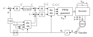
Figure 1: Control diagram of PMSM.
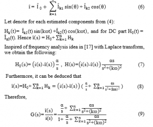
Considering the transfer function : its gain is one at and , and almost zero if not. It implies the convergence when , and other convergences of harmonic observer components.
Applying proposed observer, a method of feature extraction can be developed. Specifically, the line current is collected and transformed into the synchronous reference frame to obtain PVM, which is used as the faulty signature for the PMSM diagnosis. The amplitude of second order harmonic is computed and on-line monitored using the observer. Accordingly, whenever there is an increase in the amplitude, the alarm signal can be issued warning the fault.
3. PMSM model
The mathematical model of the PMSM in the synchronous reference frame can be expressed by [18]:
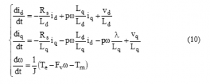
where
id, iq: d-axis and q-axis stator currents, respectively;
vd, vq: d-axis and q-axis stator voltages, respectively;
w: Angular velocity of the rotor;
l: Amplitude of the flux induced by the permanent magnets of the rotor in the stator phases;
Rs: Resistance of stator windings;
Ld, Lq: d-axis and q-axis inductances;
Te: Electromagnetic torque, ;
Tm: load torque; J: Inertia coefficient; and Fv: Friction coefficient.
Figure 1 shows the control diagram of PMSM, which is designed with the speed and stator current controllers. The line currents (ia and ib) and the rotor position (q) are the feedback of the controllers. In the next section, the simulation will be carried out to provide the necessary data for the feature extraction.
4. Estimation results
In order to demonstrate the performance of the observer, simulation of PMSM is developed in the following conditions:
- The motor is simulated using the model given in Eq. (10) of the Section 3; and the motor parameters are given in Table 2;
- The PMSM is inverter-fed and controlled to operate in speed control mode, shown in Figure 1. The reference speed is set equal to 500 rpm;
- In order to simulate the faulty condition, a resistor is added to one phase of the motor creating an unbalance condition in the stator windings, as illustrated in Figure 2, which is similar to inter-turn short circuit
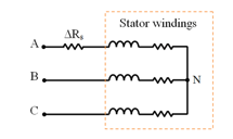
Figure 2: Stator windings with additional resistance [19].
- Three levels of load torque are applied to the PMSM system, i.e Tm = 0.05 N.m; Tm = 0.15 N.m; and Tm = 0.075 N.m, shown in Figure2; They are selected to observe whether the amplitude of the second order harmonic in the PVM signal varies due to load conditions or the appearance of fault.
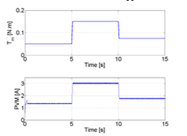
Figure 3: Torque level applied to the PMSM (upper) and PVM of stator currents (lower).
- The PVM is calculated by Eq. (11) from the two-axis currents (id, iq), which are obtained by the Park transformation of the line currents (ia, ib).
![]()
Table 1: Data of the permanent magnet synchronous motor
| Motor voltage | Vnom | 20.12 V |
| Motor current | Inom | 3.42 A |
| Load torque | Tmax | 0.2259 N.m |
| Line-line stator resistance | Rs | 0.57 Ω |
| Line-line stator inductance | Ls | 0.64 mH |
| Torque constant | Kt | 0.0592 Nm/A |
| Total inertia coefficient | J | 1.7721.10-5 N.m/rad/s2 |
| Voltage constant | Ke | 6.2 Vpeak L – L/krpm |
If the load torque depicted in Figure3 (upper) is applied to the motor, the PVM is correspondingly obtained as in Figure3 (lower).
The PVM is used as the input of the observer which computes the amplitude of second order harmonic by using the algorithm presented in section 2. The implementation of this observer is illustrated in Figure4, in which K = 10 that is obtained by tuning.
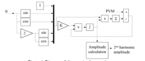
Figure 4: Diagram of observer implementation.
In order to create a reference for validation of the estimated results of the observer, the PVM is analyzed by Fast Fourier Transform algorithm. As a result, the spectral of PVM are obtained and depicted in Figs. 5, 6 and 7 for load torque levels of 0.05 N.m, 0.15 N.m and 0.075 N.m respectively. It can be seen in all figures that the amplitudes of second order harmonics of the PVM in faulty conditions are 0.04 A, 0.013 A and 0.07 A corresponding to the three load torque levels, which are much greater than that of healthy state (nearly equal zero).
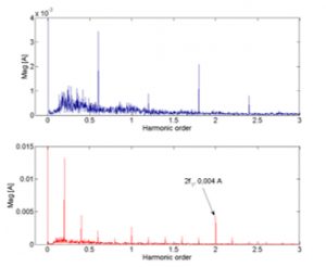
Figure 5: Three first harmonics in the FFT spectral of PVM: healthy condition (upper) and faulty condition (lower) (Tm = 0.005 N.m)
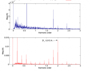
Figure 6: Three first harmonics in the FFT spectral of PVM: healthy condition (upper) and faulty condition (lower) (Tm = 0.15 N.m)
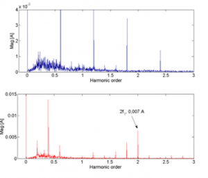
Figure 7: Three first harmonics in the FFT spectral of PVM: healthy condition (upper) and faulty condition (lower) (Tm = 0.075 N.m)
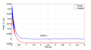
Figure 8: Observation results of 2nd harmonic amplitude of PVM Tm = 0.05 N.m
Following this, the simulation is implemented with three selected level of load torque. Simultaneously, the observer is utilized to calculate the second order harmonic amplitude. Figs. 8, 9 and 10 present the results of amplitude calculation at three given load torque levels, which are respectively compared with the FFT analysis results in Figs. 5, 6 and 7.
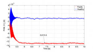
Figure 8: Observation results of 2nd harmonic amplitude of PVM (Tm = 0.15 N.m)
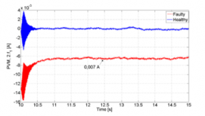
Figure 9: Observation results of 2nd harmonic amplitude of PVM (Tm = 0.075 N.m)
It can also be seen in these figures that there is an increase in the amplitude due to the fault, which varies dependent on the level of load torques. As can be seen, the FFT calculation and the observed results are in good agreement that successfully demonstrates the performance of the observer.
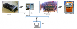
Figure 10: Test-bed of PMSM
The observer is also validated with experiment data to show the possibility of extracting the feature in the real condition which is disturbed by noise and other harmonics originated from the machine construction. The estimation is carried out offline with the data of currents and rotor position at the test-bed, depicted in Figure 10. The test-bed is composed of a Hurst PMSM, an inverter, an auto-transformer, and a real-time controller board (DSP) which allows to send the control signal to the inverter from the personal computer. The data of currents, voltages, and rotor position are acquired by using dedicated sensors. The auto-transformer is used to transform the 400 V AC voltage of the main grid into an appropriated level to supply the inverter.
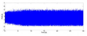
Figure 11: PVM of stator currents (experiment).
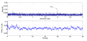
Figure 12: Observation results of 2nd harmonic amplitude of PVM (experiment).
The acquired stator currents are used to calculate the PVM, shown in Figure 11. Figure 12 presents the FFT analysis of the PVM (upper) in which the magnitude of the second order harmonic can be observed. It is then compared to the feature extraction result by the observer. The level of second order harmonic magnitude observed is at the mean value of around 0.013 A, agreed with the value in FFT analysis.
In summary, as an application of the proposed observer, the procedure for detecting inter-turn short circuit fault can be proposed that consists of following main steps:
- Acquire samples of stator currents and rotor position;
- Compute PVM of the stator currents;
- Calculate the amplitude of the second order harmonic by using the proposed observer;
- Evaluate the amplitude levels of second order harmonic in the PVM signal for the fault tripping mechanism to
detect inter-turn short circuit.
5. Conclusion
In this paper, a feature extraction based on observer has been presented in which the second order harmonics in the PVM of line currents can be successfully managed. This harmonics is not observed in the simulation PVM signal. However, it is recorded in the faulty condition at different amplitude levels due to the load variation. The feature has been also extracted from the experimental PVM signal to show the performance of the observer in the noised conditions. The advance of proposed observer-based method to FFT-based method is that it can be applied to the online feature extraction during the operation of the PMSM. Moreover, the only second order of harmonic of the PVM is analyzed that allows to obtain a narrow window of frequency in signal analysis.
As a future work, the faults characterized by different faulty frequencies and other signals in the motor will be investigated for the extraction and fault diagnosis. The works will be focused on the validation of this technique on the evaluation of further harmonic components, which can theoretically arise from different types of faults in the PMSM.
Conflict of Interest
The authors declare that there is no conflict of interests regarding to the publication of this paper.
- Y. Chen, S. Liang, W. Li, H. Liang, C. Wang, “Faults and Diagnosis Methods of Permanent Magnet Synchronous Motors: A Review,” Applied Sciences, 9(10), 2116, 2019, doi:10.3390/app9102116.
- F. Alvarez-Gonzalez, A. Griffo, B. Wang, “Permanent magnet synchronous machine stator windings fault detection by Hilbert-Huang transform,” The Journal of Engineering, 17, 3505-3509, 2019, doi: 10.1049/joe.2018.8173.
- Z. Gao, C. Cecati, S. Ding, “A Survey of Fault Diagnosis and Fault-Tolerant Techniques – Part I: Fault Diagnosis with Model-Based and Signal-Based Approaches,” IEEE Transactions on Industrial Electronics, 62, 3757-3767, 2015, doi: 10.1109/TIE.2015.2417501.
- M. Heydarzadeh, M. Zafarani, E. Ugur, B. Akin, M. Nourani, “A model-based signal processing method for fault diagnosis in PMSM machine,” in IEEE Energy Conversion Congress and Exposition, Cincinnati, Ohio, 2017, doi: 10.1109/ECCE.2017.8096575.
- S. Neild, P. McFadden, M. Williams, “A review of time-frequency methods for structural vibration analysis,” Engineering Structures, 25(6), 713-728, 2003, doi: 10.1016/S0141-0296(02)00194-3.
- E. Liu, G. Niu, S. Tang, B. Zhang, J. Williams, R. Martin, C. Moore, “Permanent Magnet Synchronous Motor Winding Fault Simulation and Diagnosis,” in Proceedings of the Annual Conference of the PHM Society, 2019, doi: 10.36001/phmconf.2019.v11i1.886.
- H. Liang, Y. Chen, S. Liang, C. Wang, “Fault detection of stator inter-turn short-circuit in PMSM on stator current and vibration signal,” Applied Sciences, 8(9), 1677, 2018, doi: 10.3390/app8091677.
- J. Faiz, H. Nejadi-Koti, Z. Valipour, “Comprehensive review on inter-turn fault indexes in permanent magnet motors,” IET Electric Power Applications, 11(1), 142-156, 2017, 10.1049/iet-epa.2016.0196.
- T. Nakai, H. Fujimoto, “Harmonic current suppression method of pmsm based on repetitive perfect tracking control,” in IECON 2007-33rd Annual Conference of the IEEE Industrial Electronics Society, 2007, doi: 10.1109/IECON.2007.4460265.
- F. Alvarez-Gonzalez, A. Griffo, B. Sen, J. Wang, “Real-time hardware-in-the-loop simulation of permanent-magnet synchronous motor drives under stator faults,” IEEE Transactions on Industrial Electronics, 64(9), 6960-6969, 2017, doi: 10.1109/TIE.2017.2688969.
- B. M. Ebrahimi, J. Faiz, “Feature extraction for short-circuit fault detection in permanent-magnet synchronous motors using stator-current monitoring,” IEEE Transactions on Power Electronics, 25(10), 2673-2682, 2010, doi: 10.1109/TPEL.2010.2050496.
- Z. Ullah, J. Hur, “A comprehensive review of winding short circuit fault and irreversible demagnetization fault detection in PM type machines,” Energies, 11(12), 3309, 2018, doi: 10.3390/en11123309.
- S.-T. Lee, J. Hur, “Detection technique for stator inter-turn faults in BLDC motors based on third-harmonic components of line currents,” IEEE Transactions on Industry Applications, 53(1), 143-150, 2016, doi: 10.1109/TIA.2016.2614633.
- F. Çira, M. Arkan, B. Gümüş, “A new approach to detect stator fault in permanent magnet synchronous motors,” in 10th International Symposium on Diagnostics for Electrical Machines, Power Electronics and Drives (SDEMPED), 2015, doi: 10.1109/DEMPED.2015.7303708.
- T. A. Shifat, J. W. Hur, “An Effective Stator Fault Diagnosis Framework of BLDC Motor Based on Vibration and Current Signals,” IEEE Access, 8, 106968-106981, 2020, doi: 10.1109/ACCESS.2020.3000856.
- T. Boileau, N. Leboeuf, B. Nahid-Mobarakeh, F. Meibody-Tabar, “Synchronous demodulation of control voltages for stator interturn fault detection in PMSM,” IEEE Transactions on Power Electronics, 28(12), 5647-5654, 2013, doi: 10.1109/TPEL.2013.2254132.
- N. T. Trinh, F. Vidal-Naquet, “Current harmonic suppression for permanent magnet synchronous motors,” in International Aegean Conference on Electrical Machines and Power Electronics (ACEMP) & 2019 International Conference on Optimization of Electrical and Electronic Equipment (OPTIM), 2019, doi: 10.1109/ACEMP-OPTIM44294.2019.9007209.
- R. Krishnan, Permanent Magnet Synchronous and Brushless DC Motor Drives, Taylor & Francis, 2009.
- H. G. Vu, H. Yahoui, H. Hammouri, “An experimental investigation of new electromagnetic field signal for stator asymmetric fault detection of doubly fed induction generators,” International Transactions on Electrical Energy Systems, 29(6), e12019, 2019, doi: 10.1002/2050-7038.12019.