
Curved Pyramidal Metamaterial Absorber: From Theory to an Ultra-Broadband Application in the [0.3 – 30] GHz Frequency Band
Volume 6, Issue 2, Page No 29-35, 2021
Author’s Name: Zeinab Fneish1,2,3,a), Hussam Ayad1, Moncef Kadi2, Jalal Jomaa4, Ghaleb Faour3
View Affiliations
1Lebanese University, Physics Departement, Faculty of Science, Beirut, 2038, Lebanon
2Normandie University, Ecole superieur d’ingenieur ESIGELEC, Research Institute, Rouen, 76800, France
3Scientific Research National Center (CNRS), Beirut, 2038, Lebanon
4Maaref University, Beirut, 2038, Lebanon
a)Author to whom correspondence should be addressed. E-mail: fneichzeinab@gmail.com
Adv. Sci. Technol. Eng. Syst. J. 6(2), 29-35 (2021); ![]() DOI: 10.25046/aj060204
DOI: 10.25046/aj060204
Keywords: Metamaterial absorber, Relative Absorptive Bandwidth, Absorption, Resonance, Curved Altitude, Pyramidal Absorber, Broadband Response

Export Citations
For its importance nowadays in a wide range of applications such as the anechoic chamber, we introduce a microwave ultra-broadband polarization-independent metamaterial absorber (MA) in the Ultra High Frequency (UHF)/ Super High Frequency (SHF) frequency bands. Through this work, we improved the Relative Absorptive Bandwidth (RAB) of the conventional pyramidal absorber (CPA) by modifying its altitude to a curved shape. As a result, the RAB increased from 25.9 % to 71.82 % with an absorptive level greater than 90% paving the way to an optimized structure for a broader band of absorption. As a second target, we looked for widening the broadband absorption of the CPA in the low-frequency region. To achieve this aim, we introduced two new prototypes. The first with a total thickness of 12.7 cm, consisting of 35 curved resonant layers where numerical simulations show an enhanced design with an absorption band from 0.3 GHz to 30 GHz referring ta a RAB of 182%. The second prototype consists of a cell containing different pyramidal absorbers grouped in-plane in a unit cell; such structures operate in complementary bands. This prototype is dedicated to combining these bands of absorption. After that, an enhancement is presented of this latest to reach a well-combined band with a RAB of 128.69%. We used for simulation, testing, and collecting results the High-Frequency Structure Simulator (HFSS) tool.
Received: 20 September 2020, Accepted: 04 February 2021, Published Online: 10 March 2021
1.Introduction
This paper is an extension of work originally presented at the 7th Mediterranean Congress of Telecommunications (CMT) conference [1] where we presented an enhanced prototype of a broadband electromagnetic Metamaterial Absorber (MA).
Because of its matched impedance due to the electric and magnetic resonance, the MA is able to omit the reflection by strongly absorbing the incident wave in the dielectric [2]. Based on the latter proposition and in different frequency bands [3-6], other designs of MAs have been introduced. Because its principle is based on resonance, the absorption bandwidth of MAs relies on narrow resonant frequencies. However, broadband absorption is an important factor in many applications one of them is the anechoic chamber. To overcome this issue, the literature proposes to increase the number of simple resonators with size variation either in longitudinal directions [6] as the pyramidal Absorber (PA) structure by stacking patches resonators or in transverse directions [7]. One of the novelties addressed in this article is a novel prototype that combines these two ways in one model in such a way that the PA structure is used as a part of a unit cell that has different PAs with size variation in the transverse direction.
Because its negligible incident angle dependence [8] and its negligible polarization dependence due to its symmetrical design geometry, the PAs structures achieve a great importance. PA is composed of a periodic array of multilayered patches forming a quadrangular pyramid where these pyramids possess resonant absorption modes at multi-frequencies in each patch layer. Due to the stacked multi-dimensional patches, we obtain a resonant response on successive multi-frequencies, which the overlapping conduct to a total absorption of the incident wave over a broad band of frequency.
Researches are rarely attempting to resolve the broadband PA below Ultra High Frequency (UHF)/ Super High Frequency (SHF) bands even though many articles have been published [9-12] focusing on the former issue in the microwave, Terahertz (THz), infrared and visible regions.
A metamaterial absorber at this region suffers from a big dimension view of its wavelength dependence. In literature, most of the miniaturized MA that is operative in low frequencies has a narrow band response [13]. Besides, from the industrial point of view, regarding the absorber operation, there exists always a problem of immensity in the frequency band [0.3-1 GHz]. Also, in the latest anechoic chamber, the absorption at low frequency is achieved by two main ways: through heavy ferrite material or by a 1-meter thickness of pyramidal Urethane foam. This specific band gains a high importance because it includes the region of the telecommunication waves. That is why in this work, we design an ultra-broadband PA working in UHF and above regions. We will use a high permittivity dielectric material as a substrate to decrease the dimension of resonators. Moreover, we will enhance the absorption response of a pyramidal design by adding a new factor in optimization. Then the enhanced pyramidal will be used as a unit in two novel prototypes that can achieve an ultra-broadband of absorption.
The first section contains the theoretical model analysis of a conventional PA that is considered as the basic’s unit in our broadband design. The study is promoted by simulation results. The second section highlights the effect of using the curved altitude on enhancing the absorption response of the CPA by means of numerical simulations highlighting the improvement of the RAB. After that, two novel prototypes based on PA units are presented aimed to make the absorption response broader in the UHF/SHF band.
All calculations were performed on a High-Performance Cluster (HPC) of 24 cores with a systems memory of 192 GB RAM. Discrete frequency analysis mode was adjusted to make simulation results with very high precision.
2. Conventional Pyramidal Structure
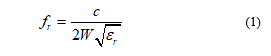
Based on the design equation of the simple patch resonator (1), the resonant absorption frequency fr is related to the side W of the patch and relative permittivity of the dielectric substrate (εr) [14]. Then, we can conclude that its response is limited to a narrow band of absorption. For that, stacking multi-dimensional patches is proposed in the literature by PA structures as an efficient way that can widen the band of absorption.
 PA design provides broadband absorption. It consists of a periodic array of pyramids with a quadrangular cross shape and a homogeneous metal ground in the bottom, the latter blocking any transmission of the incidence wave (S21 = 0).
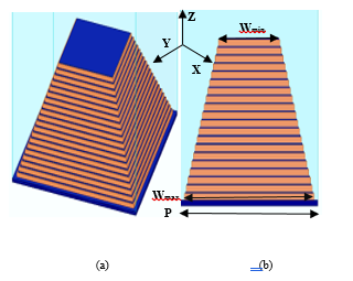 Figure 1: Design of an ultra-broadband PMA, (a) 3-D illustration of the simulation MA, (b) Side view of the PMA unit cell [1].
In this model, the thickness of the metallization layer and the dielectric layers in each patch layer are optimized to be; tm=35 μm, td = 140 μm respectively. The metal used is copper with electric conductivity of σ =5.8×10⁷ S/m. FR4 is used for the dielectric substrate with the relative permittivity of 4.4 and loss tangent equal to 0.02. In this primary model, 20 resonator layers are chosen.
In the simulation, the periodic boundary conditions are assigned along the x and y-directions. A wave port is launched along the z-direction with E field polarized along the y-direction.
RAB defined in (2) is the factor that describes the absorption bandwidth performance of an absorber.
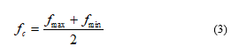
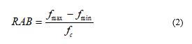 where fc is the central frequency of the absorptive band presented in (3) is given by:
 Where fmax and fmin are the upper and lower limits of a frequency range with a specific absorption level, respectively.
The absorption coefficients as a function of frequency from 10 GHz to 28 GHz were shown in Figure 2. There are 20 absorption peaks with an absorbance of approximately above 80%, corresponding to the number of dielectric patches between two neighboring metal interfaces.
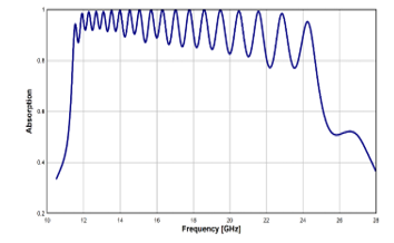 Figure 2: The simulation absorption response of the optimized pyramidal structure with dimensions of: Wmin =2.975 mm, Wmax=6.3 mm, P= 6.65mm, tm= 35μm, td= 140 μm [1]
As shown in Figure 3, Electric and Magnetic field distributions are plotted at three frequencies (11.5, 17, and 20.45 GHz).
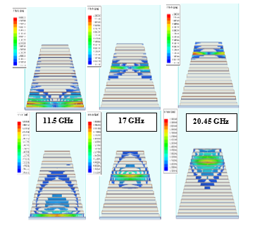 Figure 3: Obtained results of the Magnetic and Electric Magnitude distributions taken at three different resonance frequencies [1]
Results show that each two adjacent metal layers spaced with a dielectric layer can localize an electric and magnetic field at special resonant frequencies. Such resonances lead to zero-reflection by impedance matching to the free space at resonance.
From figure 3, we can observe that, at lower frequencies, the electromagnetic field is localized at the bottom layers of the pyramid. As the frequency is increased, the electromagnetic fields are localized in the upper layers of the pyramid. Since the layers of the pyramid are gradually decreased in width from the bottom to the top, they resonate at different successive frequencies that ensure an ultra-broadband absorption response. Based on this theoretical study, as the number of layer increases, the absorption window broadens gradually due to additional resonant frequencies
3. Curved Altitude Enhancing Factor
In this section, we include the numerical simulations that show the improvement in the RAB by considering the curved altitude modification on the pyramidal structure. The latter modification adds a new degree of freedom that can improve any pyramidal structure. The unit cell of the pyramidal structure in Figure 1 is considered as a criterion for evaluation of the impact of applying a curved altitude to the pyramidal structure.
Figure 4 shows three different forms of altitudes applied to the same structural parameters. We take the sawtooth altitude (Figure 4 (a)), the linear altitude (Figure 4 (b)), and the curved altitude (Figure 4 (c)).
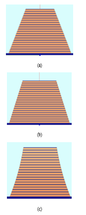 Figure 4: Diverse altitude design shapes of a Pyramidal structure. (a) Sawtooth Altitude, (b) Linear Altitude, and (c) Curved Altitude [1].
The curve altitude is drawn by a 3-point arc and optimized for the sake of achieving the best outcomes. In Figure 5, we plot the frequency-dependent absorption response for the designs shown in Figure 4.
The simulation results show that the level of absorption in linear and sawtooth altitudes is below 90% at a higher frequency, and it can cover a broad band of absorption but with an oscillator level of absorption (Figure 5 (a) and (b)). This oscillation phenomenon is explained by the need to decrease the difference in dimension between the highest patches on top to ensure nearer resonant frequencies. This result guided us to think about a novel altitude shape. With the curved altitude design, the resonance peaks, at the higher frequency, became nearer to each other and well combined that explains the increase in the RAB. Therefore, the Curved PA reaches 71.82 % RAB with an absorption level above 90% showing a larger absorption compared to that obtained by other altitude forms (see Table 1). This result paves the way to found a new parameter in optimizing such a design.
Table 1: Relative Absorption Bandwidth for different altitude form obtained by simulation results.
| RAB with Absorption level above 80% | RAB with Absorption level above 90% | |
| Sawtooth Altitude | 63.3% | 25.9% |
| Linear Altitude | 46.3% | 33.3% |
| Curved Altitude | 73.4% | 71.82% |
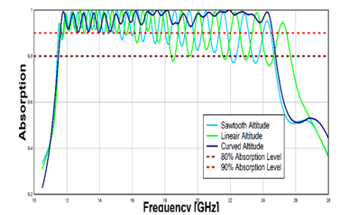 Figure 5: Absorption response for diverse altitude design shapes: Sawtooth Altitude, Linear Altitude, and Curved Altitude.
4. Absorber Prototypes with an Ultra-Broadband Absorption Spectrum
In this section, we will present two novel structures that can achieve broader absorption results by increasing the number of resonators either in transverse or longitudinal directions as addressed in the subsections below.
As we cited before, our study is directed to get a broad absorption band at lower frequencies. For that, according to the design equation (1) to get a low resonant frequency response, we shall increment the dimension of the considered patch in addition to the relative permittivity of the substrate material.
After the full parametric study, we reached a state in which we can tune the operating frequency to drive the new design to become absorptive in the UHF band by using dielectric material with εr = 55 and modifying the fundamental patch to be 72 mm.
4.1. The prototype of Adding Supplementary Patches by Altitude
Due to the role of the conic foam form in the anechoic chamber and for the goal of enlarging the band of absorption, we increased the number of supplementary patches in altitude by 15 using the same stitching method to the pyramid scaled to low frequency consisting of 20 layers as shown in Figure 6 (a). Built up from 35 stacked patches (see Figure 6(b)), the new prototype makes it possible to get a sharp peak at the top; this step can help in decreasing the interface between an electromagnetic wave and the design leading to a higher absorption compared to reflection.
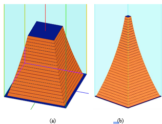 Figure 6: Optimized Pyramidal Design. (a) Prototype of optimized pyramid in UHF Band. (b) Prototype of the Pyramid Absorber after adding 15 patches, the biggest patch is 72 mm in length and the smaller one at the top is 11.7mm [1].
First, we adjust an optimized model of PA with an optimized curved altitude to be operative in the UHF region (Fig.6(a)). Figure 7 displays the spectrum of absorption of such model, it shows an absorptivity exceeding 80% in the frequency band [300-625] MHz. In this structure, we inserted the 15 supplementary layers by height (Fig. 6(b)). Figure 8 aims to verify that the proposed new design reached an ultra-broadband of absorption covering the UHF/SHF frequency regions.
Theorically, the new design should gives 35 resonant peaks of absorption referring to the basic operation of PA that declare that every patch must resonates in a unique peak of frequency. Luckily, the achieved outcomes crossed over the expectations with an additional factor of absorption at higher frequencies.
In the range [0.3 GHz – 1.92 GHz] of absorption (Phase I), we can explain the absorptive results to the successive resonant absorption modes that occurred at multi-frequencies as expected (fig.9). The reason behind the plots of the electric and magnetic field distributions in Figure 9 is to understand physically the absorption took place in Phase I. In resonant mode, both magnetic and electric resonance exist where they lead to a matching between the absorber impedance and the free space impedance then the wave is absorbed in the dielectric.
Phase II [1.92 GHz- 30 GHz] , with a level greater than 90% (Fig. 8 (b)) the ultra broad-band continues. In this region, the reason for absorption can be linked to a strong coupling between spaced patches due to the formation of some absorbing modes (see Figure 10). Two main factors clarify the observation: the high permittivity of the considered material that causes a high absorption and the conical geometry with a peaked top that may be responsible for the decrease in the reflection, and To make sure about this result, it has to be experimentally validated.
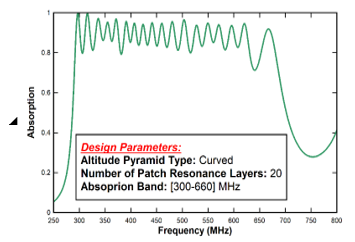 Figure 7: The absortption response of Figure 3(a) in the UHF band [1]
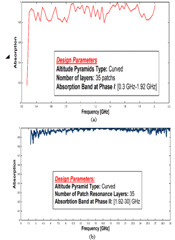 Figure 8: Absorption response of the EP design of Figure 3(b) in the UHF/SHF band after adding 15 layers. (a) Phase I of absorption. (b) Phase II of absorption [1]
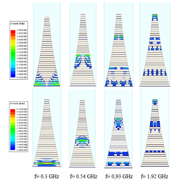 Figure 9: Simulated Electric magnitude distributions at some frequencies at Phase I of absorption [0.3 GHz – 1.92 GHz] [1]
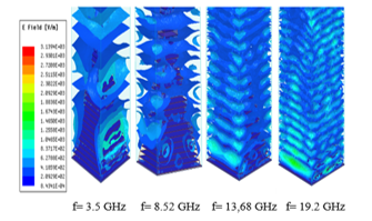 Figure 10: Simulated Electric magnitude distributions at some frequencies of the second phase of absorption [1]
4.2. The prototype of combining pyramids with complementary bands planar in one unit cell
In this section, we test the efficiency of adding supplementary resonators in the transverse direction to have the broadest absorption response. For that, we apply a novel idea that consists of grouping two kinds of curved and optimized PAs that operate on complementary frequency bands in a one-unit cell. This combined unit cell should also respect the geometrical symmetry that permits to make the model insensitive to the wave polarization as shown in Figure 11.
For that, we adjust two PAs with the same material properties to be absorptive in complementary bands (Figure 12).
As shown in Figure 12, structure 1 operates in the lower band covering [0.29-0.68 GHz] and structure 2 operates in the complementary band covering [0.68-1.48 GHz] with an absorption level greater than 80% in these two structures.
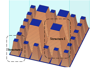 Figure 11: Structure of the combined structure operating in complementary bands
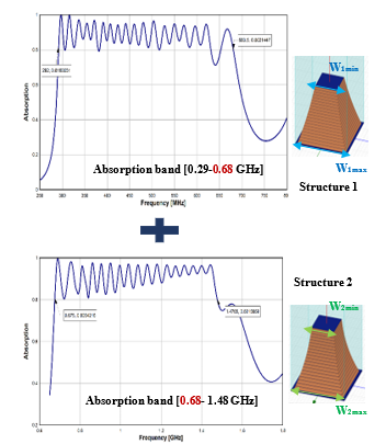 Figure 12: The operating absorption band of structures composing the unit cell with geometrical dimensions: W1max=72mm; W1min=33mm; W2max=31.5 mm; W2min= 14.7mm.
This design imposes a geometrical spacing between pyramids with the same dimensions that can degrade the grouping performance of complementary bands. For that, the periodicity between pyramids is taken to be as minimum as possible in such a way to get the pyramids closed to each other and prevent any additional spacing between the same pyramid’s dimensions.
To resolve this geometrical disadvantage an enhanced design is presented inserting a third pyramid as shown in Figure 13. The latest pyramid is structured and optimized to operate in a medial band covering [0.42 -0.99 GHz].
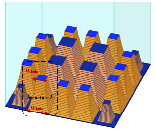 Figure 13: Enhanced Model of the combined structure, considering these geometrical dimensions for structure 3: W3max =50.22 mm; W3min = 21.06 mm.
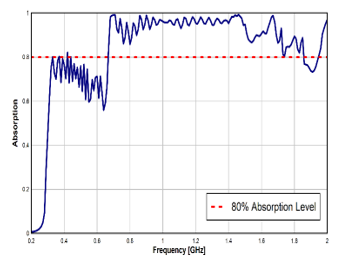 Figure 14: Absorption response of the first combined design presented in Figure 11.
From Figure 14, it is shown that the bands are not combined properly, what is particularly striking is the loss of absorption in the lower frequency band due to the increase in the distance between patches of the same size. Increasing the distance between patches will affect the damping coefficient of the structure that directly determines the level of absorption.
The enhanced structure comes to resolve such a problem by adding a third structure operating in a middle band. Results show that the bands are now combined better but a part of the lower band is still below 80% of absorption (Figure 15). By this result, we obtained an absorption band covering [0.41-1.89 GHz] with an absorption level greater than 80%. Such band refers to a RAB of 128.69 %. By this enhanced prototype, the combination is successfully obtained from [0.41 GHz-1.89 GHz]. Such a result shows that there is an extra band of absorption from [1.48 GHz- 1.89 GHz]. Figure 10 shows the absorbing modes that cause a strong coupling between spaced patch; such phenomenon represents the cause of the observed extra band of absorption.
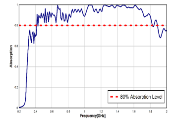 Figure 15: The absorption level of the design presented in Figure 13.
5. Conclusion
Due to the remarkable characteristics of the pyramidal design, we covered a full theoretical study in this paper. We take this structure as a basic model in our study by different geometrical shapes. The curved altitude is found as an enhancing factor where the relative absorption bandwidth increase from 63.3 % to 73.4 % with an absorption level greater than 80 %. Added to these results, we presented two novel prototypes based on the PA that can achieve a broader absorption response.
Generally, the broadband objective can be achieved by increasing the number of resonators with size variation either in transverse or longitudinal directions. That is was applied in this article based on pyramidal units instead of simple patches where they were combined in-plane and in altitude. Each idea was showed its efficiency in broadening the absorption band. We reached a RAB of 182.83 % by applying the curved pyramid of 35 layers and 128.69 % when applying the transverse combining method. The novelty in the ways of patches structuring applied in this article, admits to a RAB values unreachable in many broadband absorber essays in literature.
For achieving important results from the considered prototypes, there is a need for experimental testing after fabrication.
Acknowledgment
The Lebanese University (LU) and the National Center of Scientific Research (CNRS) and the support this work.
- Z. Fneish, H. Ayad, M. Kadi, F. Mazeh, J. Jomaah, G. Faour, “Ultra Broadband Curved Pyramidal Absorber Metamaterial in the UHF/SHF Region,” in 7th Mediterranean Congress of Telecommunications 2019, CMT 2019, IEEE: 1–4, 2019, doi:10.1109/CMT.2019.8931391.
- N.I. Landy, S. Sajuyigbe, J.J. Mock, D.R. Smith, W.J. Padilla, “Perfect metamaterial absorber,” Physical Review Letters, 100(20), 207402, 2008, doi:10.1103/PhysRevLett.100.207402.
- H. Tao, N.I. Landy, C.M. Bingham, X. Zhang, R.D. Averitt, W.J. Padilla, “A metamaterial absorber for the terahertz regime: design, fabrication and characterization,” Optics Express, 16(10), 7181–7188, 2008, doi:10.1364/OE.16.007181.
- A.-X. Wang, S.-B. Qu, H. Dai, G. Zhang, W.-J. Wang, M.-B. Yan, “Design of Ultrathin Five-band Polarization Insensitive Metamaterial Absorbers,” in 2019 IEEE 2nd International Conference on Electronic Information and Communication Technology (ICEICT), IEEE: 658–661, 2019, doi:10.1109/ICEICT.2019.8846323.
- M.A. Ghaderi, P. Enoksson, R.F. Wolffenbuttel, “CMOS Compatible Fabrication of Mid Infrared Microspectrometers Based on an Array of Metamaterial Absorbers,” in 2019 20th International Conference on Solid-State Sensors, Actuators and Microsystems & Eurosensors XXXIII (TRANSDUCERS & EUROSENSORS XXXIII), IEEE: 1580–1583, 2019, doi:10.1109/TRANSDUCERS.2019.8808691.
- C.-H. Lin, R.-L. Chern, H.-Y. Lin, “Polarization-independent broad-band nearly perfect absorbers in the visible regime,” Optics Express, 19(2), 415–424, 2011, doi:10.1364/OE.19.000415.
- A. Sellier, Absorbants à métamatériaux: étude théorique et expérimentale, 2014.
- F. Ding, Y. Cui, X. Ge, Y. Jin, S. He, “Ultra-broadband microwave metamaterial absorber,” Applied Physics Letters, 100(10), 103506, 2012, doi: 10.1063/1.3692178.
- M. Lobet, M. Lard, M. Sarrazin, O. Deparis, L. Henrard, “Plasmon hybridization in pyramidal metamaterials: a route towards ultra-broadband absorption,” Optics Express, 22(10), 12678–12690, 2014, doi: 10.1364/OE.22.012678.
- Q. Liang, W. Yu, W. Zhao, T. Wang, J. Zhao, H. Zhang, S. Tao, “Numerical study of the meta-nanopyramid array as efficient solar energy absorber,” Optical Materials Express, 3(8), 1187–1196, 2013, doi: 10.1364/OME.3.001187.
- Q. Liang, T. Wang, Z. Lu, Q. Sun, Y. Fu, W. Yu, “Metamaterial-based two dimensional plasmonic subwavelength structures offer the broadest waveband light harvesting,” Advanced Optical Materials, 1(1), 43–49, 2013, doi: 10.1002/adom.201200009.
- J. Zhu, Z. Ma, W. Sun, F. Ding, Q. He, L. Zhou, Y. Ma, “Ultra-broadband terahertz metamaterial absorber,” Applied Physics Letters, 105(2), 21102, 2014, doi: 10.1109/JPHOT.2018.2888971.
- S.T. Bui, Y. Yoo, K.W. Kim, D.L. Vu, Y. Lee, “Small-size metamaterial perfect absorber operating at low frequency,” Advances in Natural Sciences: Nanoscience and Nanotechnology, 5(4), 45008, 2014, doi: 10.1088/2043-6262/5/4/045008.
- H. Ayad, Antenna Performance Control using Metamaterials, 2012.