Cyclic Evaluation of Capacity of Recovered Traction Battery after Short-Circuit Damage

Adv. Sci. Technol. Eng. Syst. J. 6(1), 879–885 (2021);
 DOI: 10.25046/aj060197
Presented paper discusses possibilities related to the recovery of the damaged lithium batteries after the short-circuit. The recovery procedure was applied on the selected traction LiFePO4 40Ah cell which was initially short-circuited. After the short-circuit, the damaged cell has visible damage of the electro-mechanical properties. For the recovery of damaged traction cell as much as possible, the experimental recovery procedure has been proposed. For the realization of this recovery procedure, the automated workplace for the cell discharging and charging with the proposed algorithm was created. For verification of the proposed recovery algorithm, the traction cell was tested with a delivered ampere-hour test at the various discharging currents. Results of the delivered ampere-hour test of the recovered cell were compared to results of delivered ampere-hour tests of the new cell. From the final evaluation is seen that the proposed recovery algorithm can recover up to 90% of capacity within a wide range of discharge and charge current.
1.Introduction
Batteries (in general form) are increasingly applied in fully electric vehicles or hybrid electric vehicles, energy storage systems, and other consumer product. The increasing of usage lithium batteries requires their bigger production and minimization of their ecological impact like footprints of carbon dioxide. Moreover, the raw materials access must be ensured, and the cost of materials must be kept low, then production rates will dramatically rise in the next several years. To secure enough battery materials, the spent lithium for batteries, especially those for hybrid electric vehicles or electric vehicles, must be recycled or recovered and used in other energy storage systems [1-5].
In present, complete recycling of lithium batteries is very costly so recycling is unprofitable. Production of batteries from recycled materials is unattractive for manufacturers because is up to 5 times more expensive than the new battery production from newly extracted materials. One of the ways to increase number of reused batteries is to regenerate them. The batteries used in cars are unusable in a vehicle when its usable capacity falls below 60%, but can still be used, for example, like energy storage in the photovoltaic system. In this simpler application, battery can safely serve until the real end of life comes. It is assumed that up to 60% of li-ion batteries from vehicles can be used in this way [6-10].
Currently, the R&D institutions are not only involved into the research on recovery of raw materials, but also on reuse or second life of batteries which cannot fulfil the requirements of their original application area but are highly usable in less demanding application. Best example of battery second life is application of batteries from hybrid electric vehicles (HEV) or fully electric vehicles (EV) in small or medium battery storage systems (BSS) for example photovoltaic systems [11–13].
On the other side, there is also an issue that is common if operation of battery cells is considered. We can talk about improper storage or operation of cells which can resulting into the damage caused for example by deep discharge, over current discharging or short-circuit. Therefore, recovery or regeneration of such cells or harmed batteries is an important topic, due to the environment and the price of new batteries [14–18]. Nowadays, the recovery processes mainly used for NiMH and batteries lead-acid which was used in hybrid electric vehicles or large electricity storage systems. In present, lithium-based cells are largely used for e-mobility, so the topic of lithium battery recovery is more and more important, because of high lithium price [19–22].
Therefore, within the presented paper, the recovery procedure of damaged battery caused by application of long-term short-circuit is being presented. The focus is given on the traction battery cell Sinopoly LiFePO4 – 40Ah/128Wh because LiFePO4 battery type are often used as traction batteries for electric or hybrid electric vehicles. Initially is being described the procedure of the application of long-term short-circuit, followed by the detection and evaluation of the damages caused by this improper operation. Consequently, the proposal procedure of regeneration is being described, while it is based on the pulsed charging with defined amplitude of charging current and durations of pluses, followed by adequate regeneration breaks. As an evaluation of suitability of proposed regeneration approach, the experimental test of the recovered battery capacity was realized, while received results have been compared to the similar tests of undamaged new cell.
2. Short-circuit damage of traction battery
During the operation of traction batteries, several hazardous conditions which are related to the behavior of the batteries can occur. These conditions can cause damage to the battery itself. Results of operation in inappropriate conditions primarily reflect into the open-circuit voltage (OCV) drop and significant loss of the capacity. If battery operation in hazardous condition is lasting, it can cause damage to the internal structure which can lead to damage of the package of the battery. In this paper is focus on operation at long-term short-circuit. Because unwanted hazardous operational conditions result in damage of battery structure, it is important to find the most suitable recovery procedure which can be applied for battery regeneration as near as possible to its nominal state.
In this paper, the attention is focused on the investigation of regeneration 40 Ah-128 Wh Sinopoly LiFePO4 3.2 V cell after short-circuit. In Table 1 are listed main parameters of tested cell.
Table 1: Parameters of selected cell
| Electrical Parameter | Sinopoly LiFePO4 3.2 V 40 Ah | |
| Nominal voltage | 3.2 | (V) |
| Maximum charging voltage | 3.65 | (V) |
| Minimum voltage | 2.5 | (V) |
| Discharge current – maximum (continuous) | 3 | (C) |
| Discharging current – optimal | 13 | (A) |
| Charging current – maximum | 60 | (A) |
| Charging current – optimal | 20 | (A) |
| Operating temperature | −45 to +85 | (°C) |
| Capacity | 40 | (Ah) |
| Package material | plastic | (-) |
2.1. Experimental application of the short-circuit
For obtain a reference cell which can be used for recovery with proposal algorithm, selected LiFePO4 3.2 V, 40 Ah, 128 Wh battery cell was selected. Therefore, selected cell was short-circuited for obtaining reference short-circuited cell. Short-circuit, which is worst scenario of operation from safety point of view. On Figure 4 shown test set-up used for experiment of the short-circuit. This configuration uses mechanical switch rated for very high current for star of short-circuiting test. Thermo-vision camera FLIR E5 and thermo-vision camera FLIR SC 660 used for thermal analysis during short-circuit.
 Figure 1: Block diagram of set-up for short-circuit test
The measurement of current during short circuit test was provided by current meter APPA A18, while measured values were stored on NI PXI with measurement cards NI PXI 1031 using LabVIEW. For the evaluation of battery dimensions and shape changes from pictures, camera Canon EOS 6D was used.
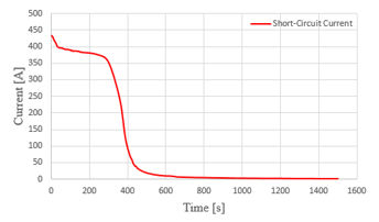 Figure 2: Current profile during the short-circuit experiment
On new battery cell which was formatted during manufacturing process was used for short-circuiting test. Secondary formatting was realized before short-circuiting test within laboratory conditions. Before short-circuiting test, battery open circuit voltage was 3,24 Vdc.
Figure 2 shows the current waveform during the short-circuit experiment. From this figure we can see that after short-circuiting, discharging current of the battery reached up to 430 A. Following more than 300 s, discharging current of the battery was over 350 A, than in next 100s is visible rapid fall of discharging current. After more than 600 s of test, current was reduced to the value of 11.5 A and finally to 2.7 A. The duration of this test was 25 min.
During short-circuited test, the battery discharging current reached more than 10C what is 3-times higher than maximal continuous discharging current determined from manufacturer. Even due to this critical operational condition, the maximum surface temperature recorded during experiment reached 49.2 °C (Figure 3), while during short-circuit test the ambient temperature was 18 °C. This maximum temperature was measured at the end of the short-circuit test and the safety pressure valve was inactive during whole duration of short-circuit.
 Figure 3: Maximal temperature during short-circuit test
The result of the short-circuit was visible mechanical change of the battery internal structure which cause change dimension of package. Figure 4 indicates structural damage after the end of the experiment, whereby depth of the package raised from 46 mm up to 54 mm, height of the package has risen from 186 mm up to 186.5 mm, and width had changed by 0.5 mm, i.e. from 116 mm down to 115.5 mm.
 Figure 4: Changes of dimensions of the tested cell after experiment of long-term short-circuit
3. Regeneration procedure application after long-term short-circuit
After the short-circuit test, the tested cell was left resting for 22 days. After this rest period, geometrical dimension of cell was checked again while no dimensional or shape change was observed compared to measured dimensions immediately after the short-circuit test. Consequently, the regeneration procedure which is explained by table 2. Was applied. The proposal procedure is based on the sequential charging with pulse charging current. This charging sequence is split into six subsequences. After finish of each subsequence, approximately 16 h resting period is applied. Each pulse subsequence duration is 100 min is divided into four cycles which duration is 25 min. The main difference between the cycles is the charging current amplitude (Table 2).
Table 2: Parameters of the regeneration procedure after long-term short-circuit.
| Subsequence | Duration | Charging current amplitude | Maximal charging voltage |
| 1 | 25 min ×
4 cycle = 100 min |
Increasing after each cycle =
0,5 – 2A |
3.65 V |
| 2 | 25 min ×
4 cycle = 100 min |
Increasing after each cycle =
2,5 – 4A |
3.65 V |
| 3 | 25 min ×
4 cycle = 100 min |
Increasing after each cycle =
4,5 – 6A |
3.65 V |
| 4 | 25 min ×
4 cycle = 100 min |
Increasing after each cycle =
6,5 – 8A |
3.65 V |
| 5 | 25 min ×
4 cycle = 100 min |
Increasing after each cycle =
8,5 – 10A |
3.65 V |
| 6 | 25 min ×
4 cycle = 100 min |
Increasing after each cycle =
10,5 – 12A |
3.65 V |
Capacity of cell was tested with delivered ampere-hour test after regeneration and after formatting procedure, while the results have been presented within [23].
During initial capacity testing the cell showed similar performance to reference, unused new cell up to 80 A of discharge current. However, for maximal 3C discharging current, the recovered cell showed just less than half of the capacity (Figure 5).
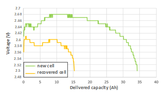 Figure 5: Voltage waveform during discharge with 3C discharging current for regenerated (yellow) and referenced cell (green)
After 28 days of storage, recovered battery was tested ten times in a row with delivered ampere-hour test. Differences in capacity values between repeated delivered ampere-hour tests were under 2%. The main issue, which was not satisfactory for the recovered cell, was the fact that for higher currents (above 2C) the battery lost its performance by more than 50 %. Therefore, second regeneration was applied once more, consequently resting period of 22 days was applied followed by formatting procedure. After this second regeneration procedure, once the cyclic testing of the capacity of regenerated battery was realized.
4. Cyclic testing of the capacity of recovered LiFePO4 traction cell
Before this cycling testing, it is necessary to charge recovered batteries as well as reference one (non-damaged, unused and formatted cell). CC&CV charging (Constant Current and Constant Voltage) is recommended for selected types of batteries. Capacity of both batteries was verified by test of delivered ampere-hours.
For the battery capacity test, five discharging and charging strategies were chosen. Each strategy is specific by a different value of discharging and charging current, while the values of discharging currents was chosen based on manufacturer recommendations of selected cell 13A-120A (0.3-3C). Cyclic experiments have been made, i.e. recovered battery had continuously undertaken verification for each of charging and discharging test for 5 times to prove robustness of proposed regeneration procedure [24-25].
 Figure 5: Block diagram of set-up for capacity testing with delivered ampere-hour test
4.1. Test of the discharged capacity
In figures 6 to Figure 10 can be seen voltage waveforms of battery cell during constant current discharge for 5 different current values (0.3C-3C). Each situation compares the situation for recovered cell and for reference (new) cell. From individual results is visible, that recovered battery exhibits the same performance as undamaged new cell.
 Figure 6: Cyclic discharging (I = 13A)
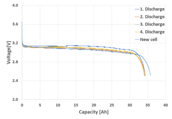 Figure 7: Cyclic discharging (I = 20A)
 Figure 8: Cyclic discharging (I = 40A)
 Figure 9: Cyclic discharging (I = 80A)
Each discharging test of recovered cell, i.e. for each value of discharge current, the measurement was validated for 4 times in order to prove stable value of recovered capacity. Simultaneously, there is a small difference between new and recovered cell. When comparing capacity for individual discharging currents, the highest difference of app. 2 Ah is visible for low discharging currents (Figure 6 – Figure 8). For higher values difference is reduced /Figure 9 – Figure 10).
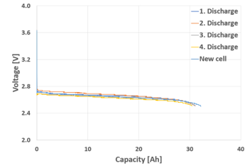 Figure 10: Cyclic discharging (I = 120A)
Within the datasheet of tested battery type it states that it is necessary to monitor the value of the temperature when discharging the cell with a current of 120 A. Temperature profile during whole discharging process by current of 120 A of recovered cell can be seen in Figure 11. From this figure is can be seen that temperature is reaching approximately 37.3 °C at the end of the discharging process. The value is much lower than critical discharging temperature listed in datasheet, which value is 85°C. This temperature profile was recorded for each discharging sequence.
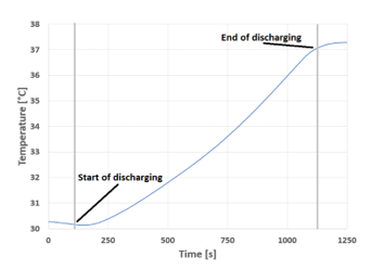 Figure 11: Temperature profile of recovered cell during discharge with 120A
The other two figures (Figure 12 and Figure 13) are representing reference results for individual situations, while independently the results for recovered and undamaged, new formatted cells are interpreted. Here the voltage waveforms are being showed during discharge with different discharging current values. At the beginning of discharging process there is a voltage drop. Voltage drop magnitude depends on the magnitude of the discharge current. The higher value of the discharge current cause the greater the voltage drop. This is caused by the effect of internal resistance of the cell. The difference between Figure 12 and Figure 13 is not markedly great, i.e. recovered cell exhibits similar behavior to undamaged. Therefore, it can be said that application of proposed capacity recovery algorithm has positively influenced the internal resistance of the cell as well.
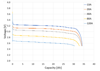 Figure 12: Voltage profile waveforms of recovered cell for various discharging currents
 Figure 13: Voltage profile waveforms of new cell for various discharging currents
4.2. Test of charged capacity
Similary to the test of the discharging process, the test of the charging process was realized for recovered and new cell.
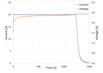 Figure 14: Charging waveforms of voltage and current (ICC = 20A)
The recovered cell was tested several times to prove stability of the recovered capacity once again. Figure 14 shows the cell voltage and current waveforms during charging profile. Here we can see the value of the constant current (in this case 20A) and the value of the charging voltage (3.65V). The charging profile is reflecting constant current, constant voltage procedure (CC/CV), what is an optimal charging method of tested type of bateries.
 Figure 15: Cyclic charging (I = 20A)
 Figure 16: Cyclic charging (I = 40A)
 Figure 17: Cyclic charging (I = 60A)
In Figure 15 to Figure 17 are the voltage waveforms during charging proces. Individual figures are specific by the value of charging current. Each graph shows 3 measurements for recovered cell and one measurement for new cell. The graphs show that charging process of new cell exhibits higher capacity if low value of charging current is applied (Figure 15). This process was also visible during discharge process by low values of current. The higher the charging current, the smaller the capacity differences between the recovered and new cell.
Figure 18 and Figure 19 are representing reference voltage profiles during charging process. Figure 18 is shown that maximum capacity of recovered cell is achieved at 33 Ah, while voltage is at the level of 3,65 V. From figure 19 can be seen that the capacity of new cell achieves approximately 37 Ah at maximum voltage level 3,65 V. Based on this results we can state, that recovered cell lost about 10% of its nominal capacity. This result is also confirmed by the voltage waveform from Figure 12 and Figure 13 where is seen, that recovered cell provides less capacity than new. However, even due to reduction of available capacity, the recovery algorithm enables to recover more than 90% of damaged cell capacity.
 Figure 18: Reference waveforms of shorted cell based on the current
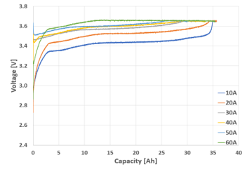 Figure 19: Reference waveforms of new cell based on the current
5. Conclusion
This paper present charging algorithm for recovery of lithium phosphate traction batteries after long-term short circuit. This recovery algorithm was applied to short-circuited Sinopoly LiFePO4 3.2V 40Ah cell. Proposal algorithm was verified with delivered ampere-hour tests. Result of these tests was compared to delivered ampere-hour test of same type battery which was, new and formatted. From comparison of tests of new and recovered battery was found that proposed algorithm can recover up to 90% within wide range of discharge and charge currents.
Conflict of Interest
The authors declare no conflict of interest.
Acknowledgment
This publication was realized with support of Operational Program Integrated Infrastructure 2014 – 2020 of the project: Innovative Solutions for Propulsion, Power and Safety Components of Transport Vehicles, code ITMS 313011V334, co-financed by the European Regional Development Fund.
- M. Frivaldsky, J. Cuntala, P. Spanik, A.Kanovsky, ”Investigation of thermal effects and lifetime estimation of electrolytic double layer capacitors during repeated charge and discharge cycles in dedicated application,” ELECTRICAL ENGINEERING, 100(1), 11-25, 2018
- S. Chamnan-arsa, K. Uthaichana, B.Kaewkham-ai, ”Modeling of LiFePO4 battery state of charge with recovery effect as a three-mode switched system,” Proceedings of the 2014 13th International Conference on Control, Automation Robotics & Vision (ICARCV), Singapore, 1712–1717, 2014, doi:10.1109/ICARCV.2014.7064574.
- J. Koscelnik, M. Frivaldsky, M. Prazenica, R. Mazgut, “A Review of Multi-elements Resonant Converters Topologies,” ELEKTRO 10th International Conference, Rajecke Teplice, SLOVAKIA, 2014
- H.D. Yoo, E. Markevich, G. Salta, D. Sharon, D. Aurbach, “On the challenge of developing advanced technologies for electrochemical energy storage and conversion,” 17 (3), 110-121, ISSN 1369-7021, 2014, https://doi.org/10.1016/j.mattod.2014.02.014
- P. Spanik, J. Cuntala, M. Frivaldsky, P. Drgona, “Investigation of Heat Transfer of Electronic System through Utilization of Novel Computation Algorithms,” ELEKTRONIKA IR ELEKTROTECHNIKA, 123(7) , 31-36, 2012
- V. D’Angelo, S. Cannavacciuolo, S. Lecce, V. Bendotti, O. Pennisi, “Enhanced hotplug protection in BMS applications. Part I: Theoretical Aspects and Practical Issues,” 2019 AEIT International Conference of Electrical and Electronic Technologies for Automotive (AEIT AUTOMOTIVE), Torino, Italy, 1-5, 2019.
doi: 10.23919/EETA.2019.8804513. - M. A. Boukhal, I. Lagrat, O. Elbannay, “Implementation of a lithium-ion battery state of charge estimation algorithm for BMS on the real time target NI myRio,” 2019 International Conference on Wireless Technologies, Embedded and Intelligent Systems (WITS), Fez, Morocco, 1-5, 2019.
doi: 10.1109/WITS.2019.8723849. - M. Frivaldsky, B. Dobrucky, G. Scelba, P. Spanik, P. Drgona, “Bidirectional Step-Up/Step-Down DC-DC Converter with Magnetically Coupled Coils,” Communications – Scientific Letters of the University of Zilina, 15(3), 21-25, 2013
- C. Huang-Jen, L. Li-Wei, P. Ping-Lung, T. Ming-Hsiang, “A novel rapid charger for lead-acid batteries with energy recovery,” IEEE Trans. Power Electron. 21(3), 640–647, 2006, doi:10.1109/TPEL.2006.872386.
- C. Sen, N. C. Kar, “Battery pack modeling for the analysis of battery management system of a hybrid electric vehicle,” Vehicle Power and Propulsion Conference, 207– 212, 2009, doi: 10.1109/VPPC.2009.5289848
- P. Spanik, R. Sul, M. Frivaldsky, “Performance Investigation of Dynamic Characteristics of Power Semiconductor Diodes,” ELEKTRONIKA IR ELEKTROTECHNIKA, 3, 3-6, 2010
- A. F. Moghaddam, A. Van Den Bossche, “An active cell equalization technique for lithium ion batteries based on inductor balancing,” in 2018 9th International Conference on Mechanical and Aerospace Engineering (ICMAE). IEEE, 274–278, 2018
- M. Cacciato, G. Nobile, G. Scarcella, G. Scelba, A. G. Sciacca, “Energy management optimization in stand-alone power supplies using online estimation of battery SOC,” 18th European Conference on Power Electronics and Applications (EPE’16 ECCE Europe), Karlsruhe, 1-10, 2016
doi: 10.1109/EPE.2016.7695559 - M. Galad, P. Spanik, M. Cacciato, G. Nobile, “Comparison of common and combined state of charge estimation methods for VRLA batteries, “ 2016 ELEKTRO, Strbske Pleso, 220-225, 2016,
doi: 10.1109/ELEKTRO.2016.7512069 - Y. Cai, Z. Zhang, Y. Zhang, Y. Liu, “A self-reconfiguration control regarding recovery effect to improve the discharge efficiency in the distributed battery energy storage system,” Proceedings of the 2015 IEEE Applied Power Electronics Conference and Exposition (APEC), Charlotte, NC, USA,, 1774–1778, 2015. doi:10.1109/APEC.2015.7104587.
- P. Spanik, R. Sul, M. Frivaldsky, P. Drgona, “Performance Investigation of Dynamic Characteristics of Power Semiconductor Diodes,” ELEKTRONIKA IR ELEKTROTECHNIKA, 3, 3-6, 2010
- M. E. Orchard, M. Lacalle, B. E. Olivares, J. F. Silva, R. Palma-Behnke, P. Estevez, B. Severino, W. Calderon-Muoz, M. Cortez, “Information-Theoretic Measures and Sequential Monte Carlo Methods for Detection of Regeneration Phenomena in the Degradation of Lithium-Ion Battery Cells,” IEEE Transactions on Reliability. 64(2), 701–709, 2015, doi:10.1109/TR.2015.2394356.
- M. Cacciato, G. Nobile, G. Scarcella, G. Scelba, “Real-Time Model-Based Estimation of SOC and SOH for Energy Storage Systems,” IEEE Transactions on Power Electronics, 32(1), 794-803, 2017.
doi: 10.1109/TPEL.2016.2535321 - P. Drgona, A. Prikopova, M. Frivaldsky, M. Priecinsky, “Simulation Based Method for Design and Application of Digital Control System, “Communications – Scientific Letters of the University of Zilina, 13(2A), 32-37, 2011
- J. Koscelnik, M. Prazenica, M. Frivaldsky, S. Ondirko, “Design and Simulation of Multi-element Resonant LCTLC Converter with HF Transformer,” ELEKTRO 10th International Conference, Rajecke Teplice, SLOVAKIA, 2014
- B. Dobrucky, M. Frivaldsky, P. Drgona, I. Kurytnik, “Measurement of swtitching losses in power transistor structure,” ELEKTRONIKA IR ELEKTROTECHNIKA, 2, 75-78, 2008
- M. Frivaldsky, P. Drgona, P. Spanik, “Experimental analysis and optimization of key parameters of ZVS mode and its application in the proposed LLC converter designed for distributed power system application,” INTERNATIONAL JOURNAL OF ELECTRICAL POWER & ENERGY SYSTEMS, 47, 448-456, 2013
- M. Frivaldsky, J. Adamec, M. Danko, P. Drgona, “Traction battery (40 Ah LiFePO4) recovery after long-term short circuit,” 2020 International Symposium on Power Electronics, Electrical Drives, Automation and Motion (SPEEDAM), Sorrento, Italy, 299-304, 2020. doi: 10.1109/SPEEDAM48782.2020.9161868.
- M. Frivaldsky, B. Dobrucky, M. Prazenica, J. Koscelnik, “Multi-tank resonant topologies as key design factors for reliability improvement of power converter for power energy applications,” ELECTRICAL ENGINEERING, 97(4), 287-302, 2015
- P. Spanik, M. Frivaldsky, P. Drgona, J. Kandrac, “Efficiency Increase of Switched Mode Power Supply through Optimization of Transistor’s Commutation Mode,” In: ELEKTRONIKA IR ELEKTROTECHNIKA, 9, 45-52, 2010
No related articles were found.