
Ferromagnetic Core Reactor Modeling and Design Optimization
Volume 6, Issue 1, Page No 810-818, 2021
Author’s Name: Subash Pokharela), Aleksandar Dimitrovski
View Affiliations
Department of Electrical and Computer Engineering, University of Central Florida, Orlando, 32816, USA
a)Author to whom correspondence should be addressed. E-mail: pokharelsbs@ieee.org
Adv. Sci. Technol. Eng. Syst. J. 6(1), 810-818 (2021); ![]() DOI: 10.25046/aj060190
DOI: 10.25046/aj060190
Keywords: Magnetic equivalent circuit (MEC), Leakage permeance, Finite element analysis (FEA), Multi-Objective (MO) Optimization, Genetic algorithm (GA)

Export Citations
This article presents an analytical model of a single-phase ferromagnetic core power in- ductor (reactor) based on a magnetic equivalent circuit (MEC). The MEC model consists of magnetomotive forces (MMFs) and reluctances for all flux paths: magnetic core and leakage flux paths. The MEC elements are found established on the characteristics of the ferromagnetic material and the reactor’s dimensions. Then the inductances of the reactor are determined using the MEC for a group of Silicon Steel (Si-Fe) sheets, which are juxtaposed with the inductances obtained using the finite element analysis (FEA) method. This comparison corroborates the MEC presented here. Furthermore, for the unsaturated (linear) region of the B-H characteristics of the same sets of Si-Fe materials, the inductive reactance closed-form solution of the reactor is obtained as a function of the design parameters. As an application example of the presented analytical model, reactor design optimizations (single-objective and multi-objective) are formulated and solved based on the derived closed-form reactance expression resulting in a reactor not only optimized in reactance but also in terms of material use and size.
Received: 30 August 2020, Accepted: 13 January 2021, Published Online: 05 February 2021
1. Introduction
This article augments the underlying work initially introduced in the 2019 North American Power Symposium (NAPS) [1].
Inductors (or the reactors in power engineering) are fundamental and most uncomplicated circuit elements that provide economical, sturdy, and efficient solutions to a spectrum of power system intricacies. The inductors have been used to limit fault and load current, compensate reactive powers, filter harmonics, damp the transients, and balance the loads, to mention a few applications in the electric power system. As a result of the significant expense and restricted usefulness for sufficient and optimal AC flow controls with FACTS devices, inductors are considered a superior alternative in power systems [2]. The use of reactors can be in conjunction with improving electric power quality, especially in the ever-changing contemporary power networks. The reactors can be connected either in series or parallel with the network based on a particular application. Contingent upon the voltage and power ratings, they can be either dry-type or oil-submerged sort. Usually, dry-type series reactors are made with air cores, and oil-immersed shunt types are made with ferromagnetic cores. Powdered core reactors, which are manufactured by the compression of the very fine particles of the magnetic materials, are preferred for high-reliability military and space applications because they are robust against shocks, vibrations, and nuclear radiations. Also, flux containment is better in powdered core compared to the ferromagnetic cores [3]. A simple schematic of a single-phase (1 − Φ) ferromagnetic core reactor for use in power systems is shown in Figure 1.
The inductor is symmetrical with non-ferromagnetic (air) gaps in the center of the inner leg. Over the gaps, there is AC winding connecting to the AC circuit. The gaps are used to limit the magnetic flux in order to prevent reactor’s saturation from the rated operating supply. The core of ferromagnetic reactors is made of a material with high permeability that acts as an excellent conductor for magnetic flux. The ferromagnetic core’s ability to conduct and concentrate the magnetic flux flow and, consequently, the reactor’s inductance is dictated by its permeability. The relationship between the flux flow in the ferromagnetic core and the current supply through the coils of an electromagnetic device (like the reactor) is nonlinear. The rate-of-change (ROC) of flux for the field strength shifts from moderate to rapid to low when the operating condition shifts from the inception to linear to the saturated region. Generally, magnetic power devices’ operation is not recommended in the saturation region, where more increment in MMF supply produces a minuscule change in flux. The operation of such devices in the saturation region increases the magnetizing current, responsible for increased losses and possible hazardous operating conditions. For some applications which work on the principle of the magnetic amplifier (MA), like continuously varying series reactor (CVSR) and fault current limiters (FCL), the inductance of the device is changed without any moving parts. The inductance variation is achieved with the help of DC bias supply by controlling the permeability and saturation of the ferromagnetic core as described in [2, 4]. The use of the laminated ferromagnetic core is the general practice to lower core losses; the ferromagnetic core in Figure 1 is shown as a solid rectangular core for simplicity only.Placing non-ferromagnetic gaps with magnetic properties similar to free space in the ferromagnetic core is also common. The effective permeability and the inductance of the device get reduced by such non-ferromagnetic gaps. However, the device’s usable range of operation gets increased with dominant reluctance in the magnetic circuit. Likewise, the non-ferromagnetic gaps assume a crucial part in making the flux flow sensitivity lower to external conditions like temperature. The adequate selection of the air gap dimension is an essential job of the reactor designer because there is a need to struck an equilibrium between avoiding core saturation with a significant gap and imposed constraints to achieve the desired value of the inductance.
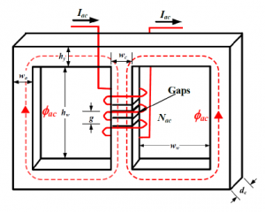
Figure 1: Ferromagnetic core reactor and its dimensions
FEA based methods are usually adopted for accurate parameter calculations and characterization of the electromagnetic devices. This numerical method can be tedious with a tremendous computational burden. It also lacks closed-form solutions. Therefore, it is not suitable for the repetitive design processes and dynamic analyses of magnetic power devices [5, 6]. In [7] and [8], the authors introduced the magnetic equivalent circuit (MEC) based method a long time ago. MEC is an alternative magnetic field modeling method for electromagnetic devices with a considerably reduced computational resources requirement. The MEC approach is based on the design inputs, material characteristics, and physical device geometry. It represents such devices with lumped magnetic circuit components: magnetomotive forces (MMFs) and reluctances. The MEC representation is considered coarser than the FEA but more acceptable than the electrical-equivalent lumped parameter models, which are based on fundamental equations. Hence, MEC is considered a bargain between those approaches in terms of computational resource need and accuracy [9, 10]. MEC approach is based on the design inputs, material specifications, and geometry of the device. The inductance calculation of a device is straightforward with this approach. MEC has the ability to accommodate local saturation effects; however, because of the eddy current and skin effects, the MEC representation becomes challenging. A comprehensive understanding of the device in consideration and a significant engineering judgment is required to generate a reluctance network with spatial discretization [9]–[13].
A great deal of engineering time and experience can be avoided with the optimization-based design process, which can produce a better design with less engineering effort [14]. A reactor’s design can involve many performance targets, some more important than others, with a set of constraints. With multi/many-objective design optimization, the feasible solution space might be discontinuous and non-convex. The evolutionary algorithms are typically chosen for such problems. A large number of design evaluations are necessary to produce a Pareto optimal front, and approximate analytical models make such computations efficient. In this article, the constrained single objective (SO) and multi-objective (MO) optimization design formulations, coupled with the detailed MEC-based analytical model that captures the reactor’s electromagnetic behavior, are presented. These design examples signify the importance of computationally efficient and accurate analytical MEC models for the reactor’s design optimization.
The article is structured as follows. Section 2 proposes an adequately precise yet simple MEC for a gapped ferromagnetic core reactor. The inclusion of the fringing fluxes in the MEC proposed in the previous section improves its accuracy. The methodology for the confirmation of the MEC model is presented in Section 3. The next section follows the methodology introduced with a case study for a set of Silicon Steel (Si-Fe) ferromagnetic materials. The design optimization examples are presented in Section 5, facilitated by the reactance expressions obtained from the validated MEC. Based on the proposed MEC, its validation, and optimization examples, conclusions are drawn in Section 6.
2. Magnetic Equivalent Circuit
The dimensions of the simple single-phase gapped ferromagnetic core reactor are shown in Figure 1. The gaps (air) in the core make the leakage flux not influential for the reactor’s magnetostatic characterization. For this reason, an arbitrary winding configuration choice is made for this device. The reactor features two windows of width ww and height hw. wo and wc are the widths of the exterior and middle leg, respectively. The central leg has non-ferromagnetic gaps of elevation g which stretches dc into the surface, which is the same throughout the reactor. Both top and bottom yokes have the same height of hy.
Figure 2 represents one of the simplest possible MECs of the reactor. The reluctances (resembling resistors from electric circuits) in the proposed MEC are positioned to interpret the accurate reactor physical structure. Similarly, the MMF source position (resembling voltage source from the electric circuit) in the MEC indicates the winding position in the reactor. The ferromagnetic core reluctances are denoted by R1 − R7, dependent on the magnetic flux through the corresponding elements. In MEC, these reluctance are shown to be a function of flux.
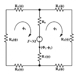
Figure 2: Magnetic equivalent circuit
However, the non-ferromagnetic air gap reluctance (R8 in Figure 2) is fixed and does not depend on the corresponding flux. The MMF source in the middle leg of the proposed MEC is the product of the number of winding turns (N) and current supply through it (I), i.e., F = NI. In Figure 2, loop fluxes are represented by φ1 and φ2, making the inner leg branch flux to be (φ1 − φ2) in the specified direction.
For a representative branch k, the generalized reluctance is:
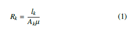
In equation (1), Ak and lk are cross-sectional area normal to the flux flow direction and length of branch element, respectively, and µ is the permeability (absolute) of the material used. The absolute permeability depends on the type of flux path, based on which the reluctances can be categorized into:
2.1 Core Piece Reluctance
The reluctances of ferromagnetic core pieces are intrinsically nonlinear. The reluctance of each ferromagnetic element in the MEC depends on the material property, physical geometry, and supply through the winding around the core. The core piece’s absolute permeability can be demonstrated as a function of either flux density (B) or flux intensity (H). Considering the symmetry of the reactor, based on (1), the characteristic core piece reluctances can be written as:
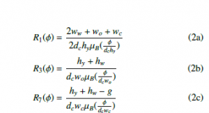
Also, R1(φ) = R2(φ) = R4(φ) = R5(φ) and R3(φ) = R6(φ). Each branch reluctance in (2) has absolute permeability represented as the functions of flux density through them. In [15], the author describes the process of finding these absolute permeabilities, which can be summarized by the following expressions.
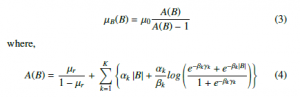
In equation (4), B represents the magnetic flux density; µr and µ0 are the relative and absolute permeabilities, respectively. Here, anhysteretic characteristics are considered with the reactor operating in the linear region. Moreover, α, β, and γ are the permeability function parameters for select core materials.
An iterative numerical search is needed for each branch of the MEC corresponding to the core piece ferromagnetic components to find a value of reluctance, given some initial values for the flux density. Figure 3 shows the flowchart summarizing this iterative process. The absolute permeability calculation is the first step of the iterative process. For mesh circuit analysis, permeability as a function of flux density is preferred. Using the absolute permeability (µ ≡ µB(B)), the reluctance of each piece can be calculated using (1). In the next step, each branch is represented in the standard general form: a series combination of an MMF source and the reluctance.
Based on the complete circuit element formation, mesh analysis is carried out to find the fluxes through each loop. Except for the first iteration, as indicated in the flowchart, the stopping criteria for the iterative process are the maximum number of iterations and branch flux relative error between consecutive iterations.
2.2 Air Gap Reluctance
In the MEC model of Figure 2, the reluctance R8 is the air gap reluctance. It is a constant reluctance without any dependence on the flux passing through it. Following (1), the reluctance of the air gap is given by:

While getting reluctance in (5), it is assumed that the cross sectional flux flow between the top and bottom of the air gap is streamlined. However, there exists a portion of a flux that flows in the vicinity of the air-gap corners spreading in all directions, which is known as the fringing flux. Because of this flux, the effective cross-sectional area of the air gap is increased, resulting in decreased air gap reluctance. The fringing fluxes should be incorporated into the air gap reluctance computation to make the MEC highly accurate.
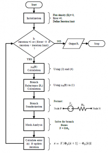
Figure 3: Iterative non-linear reluctance calculation flowchart
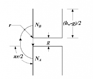
Figure 4: Fringing permeance calculation
The Ampere’s circuital law, which relates the current to the associated magnetic field, can be described by (6) representing the magnetic field intensity H(A/m) over a closed path c to be equivalent to the current enclosed by that path (Ienclosed.)
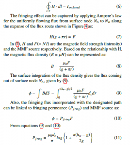
For the central leg with air gap, the depth and the width are the same; therefore, the total fringing permeance is four times the Pfring.
Hence, the air gap reluctance can be given by:
![]()
3. MEC Validation Methodology
A meshed circuit analysis based on Kirchhoff’s laws from electric circuits can be adopted to solve the proposed MEC once each MEC element is determined. This analysis gives flux through each branch and loop of the MEC. The physical law of energy conversation holds for the MEC. Therefore, a balance between the energy generated by the MMF source(s) and energy dissipated into the reluctances always exists. The energy balance principle can be exploited to find the overall equivalent inductance of the inductor directly. From [16] the reactor’s inductance is:
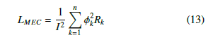
Here, 1 ≤ k ≤ n is the index representing each branch in the MEC with a total number of branches being n; while Rk and φk are the reluctance and flux through the branch k respectively. Furthermore, the winding coil has current I following through it.
By performing different analyses (magnetostatic/transient) using the software packages based on FEA can give the inductance of a reactor. A three-dimensional (3-D) model of an inductor with minimal error tolerance set up can compute the inductance (apparent/incremental) accurately in the FEA software package.
The proposed MEC of the reactor is verified by comparing the equivalent inductances obtained from MEC as described in (13) using MATLAB R [1], and the FEA based approach using ANSYS Maxwell R [2]. The following case study presents the comparative analysis.
4. Case Study
A contextual analysis for the affirmation of the presented analytical model is carried out in this section, followed by the closed-form reactance calculation based on the validated model.

Figure 5: Candidate ferromagnetic material characteristics
4.1 MEC Validation
A single-phase reactor considered for the MEC validation has the parameters, as shown in Table 1.
Table 1: Gapped core reactor parameters
A set of magnetic core materials (Si-Fe) is considered with accompanying qualities (relative permeability, permeability function parameters, and maximum flux densities) extracted from [17]. The magnetic properties (B-H curves) for these materials generated according to [18] are shown in Figure 5. The two approaches described in the previous section are applied to calculate and compare the inductance of the reactor made up of each of the given materials.
For both linear and non-linear regions of the magnetization characteristics of Si-Fe, it is clear that the anhysteretic curve of Hiperco50 is considerably different from the others, as can be seen in Figure 5.
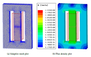
Figure 6: FEA simulation Results for Si-Fe Hiperco50 core
Figure 6 shows 3-D FEA results for the reactor with the Si-Fe Hiperco50 core with the parameters from Table 1. The adaptive meshing has been applied to the model to make the simulation more accurate. The figure also shows the flux density distribution throughout the core, and it can be seen that the middle leg has the highest flux density.
For every core materials from the group, the inductances using both approaches and relative error between them are summarized in Table 2. The errors are within 1% for each of the materials. This minimal range of errors across a group of Si-Fe materials confirms the accuracy of the proposed MEC.
4.2 Reactance Calculation For a 60 Hz system, a single-phase inductor’s reactance can be expressed as: |
Table 2: Inductance comparison
| Si-Fe Materials | Inductance (mH) | % Error | |
| MEC | FEA | ||
| M19 | 7.853 | 7.880 | 0.348 |
| M36 | 7.905 | 7.871 | -0.427 |
| M43 | 7.910 | 7.935 | 0.310 |
| M47 | 7.831 | 7.904 | 0.925 |
| Hiperco50 | 8.012 | 8.081 | 0.850 |

here, Rm is the equivalent reluctance of the reactor. A circuit reduction on MEC can be applied to obtain it, as shown in Figure 7.
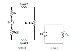
Figure 7: MEC reduction
As the design of the reactor is symmetrical, a circuit simplification by the parallel combinations of the reluctances corresponding to the yoke and vertical leg transforms the MEC from Figure 2 to Figure 7a. Furthermore, the series reluctances in a single loop MEC in Figure 7a can be combined to achieve the simplest MEC as in Figure 7b. Accordingly:
![]()
In Figure 7, Ry ≡ {R1 = R2 = R4 = R5} and Rl ≡ {R3 = R6}. A further break down of (16) for a linear operation region (in the magnetization characteristic curve) returns:
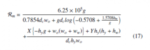
A symbolic mathematical computation program called MATHEMATICA R [3] has been used to obtain this simplified expression. For different core materials, the coefficients X and Y in (17) are summarized in Table 3.
Table 3: Reactance coefficients
| Si-Fe Materials | Coefficients | |
| X | Y | |
| M19 | 44.324 | 66.486 |
| M36 | 58.996 | 88.494 |
| M43 | 51.342 | 77.012 |
| M47 | 86.369 | 129.554 |
| Hiperco50 | 36.473 | 54.710 |
5. Design Optimization
5.1 Single Objective Optimization
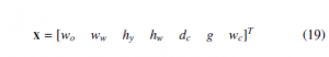
An example of a single objective optimization problem is set up using the expression for the reactance of the reactor. The use of minimal material for the core is the objective while complying with several design constraints. Here, it is assumed that the reactor core is made up of Si-Fe M36 material. The design constraints include the target reactance, flux density limits for each element of MEC (n = 8), and minimum and maximum limits for the design parameters. The design parameter vector (19) consists of all design parameters. Their ranges and the initial points are summarized in Table 4.
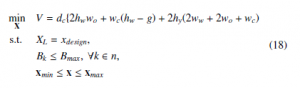
In (18), Bmax = 1.25 T is the maximum flux density in the linear region of the B-H curve for Si-Fe M36, and xdesign = 2 Ω.
Table 4: Domain of design parameters
| Parameters | xmin (m) | xmax (m) | xinitial (m) |
| wo | 0.0762 | 0.1016 | 0.0889 |
| ww | 0.0559 | 0.0762 | 0.0635 |
| hy | 0.0762 | 0.1016 | 0.0889 |
| hw | 0.3739 | 0.5080 | 0.4572 |
| dc | 0.0762 | 0.1016 | 0.0889 |
| g | 0.0015 | 0.0023 | 0.0020 |
| wc | 0.0762 | 0.1016 | 0.0889 |
A non-linear solver called ’Knitro’ with YALMIP toolbox from MATLAB R has been used to solve this non-linear optimization problem. Table 5 summarizes the optimization results.
Table 5: SO optimization results
| Parameters | Value (m) | Parameters | Value (m) |
| ww | 0.0559 | wo = wc | 0.0762 |
| hy | 0.0762 | hw | 0.3739 |
| g | 2.286 × 10⁻³ | dc | 0.0762 |
The optimal (minimum) ferromagnetic core material volume is found to be 1.0452 × 10⁻²m3. An approximate ’back-of-theenvelope’ calculation for the volumetric minimization of the reactor with some educated guess regarding the constraints verifies the presented results. The air-gap (g) is very sensitive towards the reactance and the flux density in the core; however, it has a minimal impact on the reactor’s total ferromagnetic volume. Therefore, the constraint set x other than g can be guessed towards the minimum limit to get the minimum ferromagnetic volume. If x is chosen to be xmin, the ferromagnetic volume would be 1.0457 × 10⁻³m3.
The optimal ferromagnetic volumes for different Si-Fe materials are summarized in Figure 8. In the figure, the ferromagnetic volumes are very near each other; however, the price difference between the materials will impact material selection.
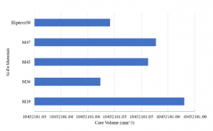
Figure 8: Optimal core volume comparison
5.2 Multi-Objective Optimization
Reactance is the most important characteristic of the ferromagnetic core inductor. In addition to the core material volume minimization, an additional objective of reactance maximization is introduced here. The multi-objective (MO) optimization searches a vast design space and is quite effective in finding optimal machine designs. An evolutionary population-based genetic algorithm [19] is implemented to solve a MO reactor optimization problem. A genetic algorithm (GA) can find multiple solutions from a population of solution candidates in one execution, which is not possible with classical optimization [14].
The goal of this design example is to come up with a singlephase power reactor design that has a reactance of at least Xmin, and maximum ferromagnetic core flux density below Bmax. It is desirable to minimize the reactor’s ferromagnetic core material volume and maximize the reactance at the rated system conditions.
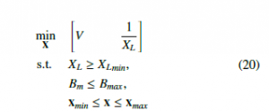
The ferromagnetic core material used in this optimization problem is the same material used for single objective optimization problem described in the previous section (Si-Fe M36). The optimal reactor would have a reactance of at least 1.5 Ω (Xmin) and the flux density of the 1.25 T (Bmax) so that the operation of the reactor is within the linear region of the characteristics curve of the selected core material for the rated supply. In 20, the flux density has been bounded only for the middle leg flux density because it is the dominant flux density region. The gapped middle leg flux density can be approximated by:

The parameter bounds are the same as in the previous section, given in Table 4. The free parameter vector is represented by (19). The symbols in parameter vector are as defined in Table 1. It is assumed that the window spaces are sufficient for the winding.
The fitness function for the MO optimization problem can be defined as:
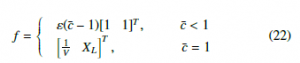
In (22), ε–a small positive number (in order of 10−10)– does not have an influence on the optimization outcomes but is appropriate for the observation of the optimization progress. And, c¯ is the aggregate constraint of the MO problem, which is:

where, nc is constraint number (here, nc = 2). Once XL and Bm have been evaluated using (14) and (21), constraint functions can be put together as (24):
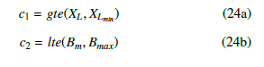
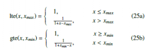
where, gte() and lte() are greater-than-or-equal-to and less-than-or-equal-to functions, respectively. These functions are defined as:
The MO optimization is carried out using GOSET [20], a MATLAB-based genetic optimization toolbox. The optimization has been performed with a population size of 1500 over 2000 generations with the specifications described by Table 6, and the parameter bounds given in Table 4.
Table 6: Genetic algorithm parameters
| Parameters | wo | ww | hy | hw | dc | g | wc |
| Encoding | log | log | log | log | log | log | log |
| Chromosome | 1 | 1 | 1 | 1 | 1 | 1 | 1 |
Table 7 summarizes the GA options carried out in the different steps of the MO optimization.
Table 7: Summary of GA options implemented
| GA | Elitist nondominated sorting GA(NSGA-II) [21] |
| Selection | Tournament selection |
| Death | Random replacement |
| Gene repair | Hard limiting |
| Scaling | Offset scaling |
Figure 9 represents the objective space at the end of the optimization, where each point represents the objectives of the corresponding design. The objective space plot is according to the fitness function definition. Therefore, reactance is plotted against the reciprocal of the ferromagnetic core material volume. The design points can be divided into nonviable, dominated, and nondominated design sets. The nonviable designs are near the origin and the negative axes of the objective space. The figure indicates the distinct design sets which are viable but dominated or nondominated.
Figure 10 shows only the nondominated designs with the axes representing the reactance and the material volume. This plot clearly shows the tradeoff between the objectives. A sample design on the Pareto optimal front is also indicated. The parameters representing the sample design are summarized in Table 8.
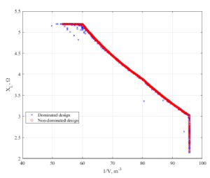
Figure 9: Objective design space
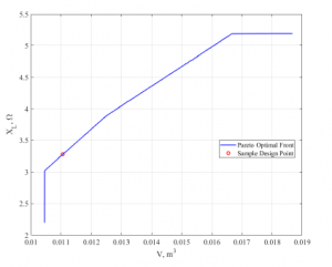
Figure 10: Pareto frontier boundary
Table 8: Sample design results
| Parameters | Values (m) | Parameters | Values (m) |
| wo | 0.085 | ww | 0.05589 |
| hy | 0.076233 | hw | 0.3739 |
| dc | 0.0762 | g | 0.001524 |
| wc | 0.0762 |
For the sample design, the ferromagnetic material volume is 0.011176 m3, and the reactance of the inductor is 3.32 Ω. This reactance is above the minimum limit XLmin, and the flux density is found to be 1.137 T, which is less than the flux density limit Bmax.
To check the validity of the sample design obtained above, a 3-D FEA model is created again with the parameters from Table 8. The magnetostatic analysis from FEA shows that the reactance of the sample design is 2.96 Ω, which is ≈ 12% off from the MO optimization results. It is a fairly good result considering the simplicity of the model used, and more accurate than a spreadsheet-based design typically used by manufacturers.
6. Conclusions
In this article, a systematic analytical representation was proposed for a 1-Φ ferromagnetic core air-gapped inductor based on MEC. For a set of Si-Fe materials for core, the proposed MEC was substantiated after collating the inductances obtained by using the 3-D FEA method. The minuscule error of the inductance values throughout the entire group of materials validated the proposed model. Furthermore, when the ferromagnetic core is in the unsaturated (linear) region of the operation, an inductor reactance expression was derived as a function of design parameters. To illustrate one of the applications of the suggested systematic model, both SO and MO optimization problems were formulated and solved. They prove the MEC’s applicability for obtaining optimal reactor designs for a specific application and highlight its efficiency and importance.
The future work will include reactor design improvements with more complex models, including more detailed flux leakages, and analyses (loss and thermal), as well as data from tests on the physical device with comparison of computational and experimental results.
Conflict of Interest
- S. Pokharel, A. Dimitrovski, “Analytical Modeling of A Ferromagnetic Core Reactor,” in 2019 North American Power Symposium (NAPS), 1–6, 2019, doi:10.1109/NAPS46351.2019.9000352.
- A. Dimitrovski, Z. Li, B. Ozpineci, “Magnetic Amplifier-Based Power-Flow Controller,” IEEE Transactions on Power Delivery, 30(4), 1708–1714, 2015, doi:10.1109/TPWRD.2015.2400137.
- C. W. T. McLyman, Transformer and inductor design handbook, CRC press, 2017.
- A. Dimitrovski, Z. Li, B. Ozpineci, “Applications of saturable-core reactors (SCR) in power systems,” in 2014 IEEE PES T&D Conference and Exposition, 1–5, 2014, doi:10.1109/TDC.2014.6863404.
- A. Deihimi, “Improved model of saturated regions in Magnetic Equivalent Cir- cuits of highly saturated electromagnetic devices,” in 2008 11th International Conference on Optimization of Electrical and Electronic Equipment, 45–50, 2008, doi:10.1109/OPTIM.2008.4602385.
- M. Moallem, G. E. Dawson, “An improved magnetic equivalent circuit method for predicting the characteristics of highly saturated electromagnetic devices,” IEEE Transactions on Magnetics, 34(5), 3632–3635, 1998, doi: 10.1109/20.717858.
- E. Lwithwaite, “Magnetic equivalent circuits for electrical machines,” in Pro- ceedings of the Institution of Electrical Engineers, volume 114, 1805–1809, IET, 1967.
- C. Carpenter, “Magnetic equivalent circuits,” in Proceedings of the Institution of Electrical Engineers, volume 115, 1503–1511, IET, 1968.
- M. Amrhein, P. T. Krein, “3-D Magnetic Equivalent Circuit Framework for Modeling Electromechanical Devices,” IEEE Transactions on Energy Conver- sion, 24(2), 397–405, 2009, doi:10.1109/TEC.2009.2016134.
- S. D. Sudhoff, B. T. Kuhn, K. A. Corzine, B. T. Branecky, “Magnetic Equiv- alent Circuit Modeling of Induction Motors,” IEEE Transactions on Energy Conversion, 22(2), 259–270, 2007, doi:10.1109/TEC.2006.875471.
- J. Cale, S. D. Sudhoff, Li-Quan Tan, “Accurately modeling EI core inductors using a high-fidelity magnetic equivalent circuit approach,” IEEE Transactions on Magnetics, 42(1), 40–46, 2006, doi:10.1109/TMAG.2005.859439.
- B. N. Cassimere, S. D. Sudhoff, D. H. Sudhoff, “Analytical Design Model for Surface-Mounted Permanent-Magnet Synchronous Machines,” IEEE Trans- actions on Energy Conversion, 24(2), 347–357, 2009, doi:10.1109/TEC.2009. 2016139.
- A. Taher, S. Sudhoff, S. Pekarek, “Calculation of a Tape-Wound Transformer Leakage Inductance Using the MEC Model,” IEEE Transactions on Energy Conversion, 30(2), 541–549, 2015, doi:10.1109/TEC.2015.2390260.
- S. D. Sudhoff, Optimization-Based Design, 1–44, Wiley-IEEE Press, 2014, doi:10.1002/9781118824603.ch01.
- S. D. Sudhoff, Magnetics and Magnetic Equivalent Circuits, 45–112, Wiley- IEEE Press, 2014, doi:10.1002/9781118824603.ch02.
- S. Pokharel, A. Dimitrovski, “A Gapless Ferromagnetic Core Reactor – Mag- netic Equivalent Circuit and Inductance,” in 2019 IEEE Power Energy Soci- ety General Meeting (PESGM), 1–5, 2019, doi:10.1109/PESGM40551.2019. 8973400.
- S. D. Sudhoff, Selected Magnetic Steel Data, 443–444, Wiley-IEEE Press, 2014, doi:10.1002/9781118824603.app3.
- G. M. Shane, S. D. Sudhoff, “Refinements in Anhysteretic Characterization and Permeability Modeling,” IEEE Transactions on Magnetics, 46(11), 3834–3843, 2010, doi:10.1109/TMAG.2010.2064781.
- D. S. Weile, E. Michielssen, “Genetic algorithm optimization applied to electro- magnetics: a review,” IEEE Transactions on Antennas and Propagation, 45(3), 343–353, 1997, doi:10.1109/8.558650.
- S. Sudhoff, Y. Lee, “GOSET Manual Version 1.03,” Available from Scott Sudhoff, Purdue University School of Electrical and Computer Engineering, 2004.
- K. Deb, A. Pratap, S. Agarwal, T. Meyarivan, “A fast and elitist multiobjective genetic algorithm: NSGA-II,” IEEE Transactions on Evolutionary Computa- tion, 6(2), 182–197, 2002, doi:10.1109