An Innovative Angle of Attack Virtual Sensor for Physical-Analytical Redundant Measurement System Applicable to Commercial Aircraft

Adv. Sci. Technol. Eng. Syst. J. 6(1), 698–709 (2021);
 DOI: 10.25046/aj060176
The angle of attack is a critical flight parameter for commercial aviation aircraft, because automatic envelope protection systems rely on it to keep the aircraft within its safe flight envelope. Faulty measurements of the angle of attack could have catastrophic effects, leading to aircraft loss of control in flight and fatalities, as demonstrated by the recent accidents involving the Boeing 737-MAX. This paper presents a novel approach to the measurement of the angle of attack, which uses one virtual sensor and two physical sensors to implement a physical-analytical redundant system that is robust to a single fault of the physical sensors. The virtual sensor is based on an innovative and reliable estimator of the angle of attack. It was originally developed to provide General Aviation pilot with an accurate indication of trend toward stall, and has been suitably customized to fit its application to commercial aviation. One of the peculiarities of the redundant measurement system is that its implementation on-board several existing commercial aviation aircraft only needs the integration of a software code and does not require any installation of additional physical sensors. The proposed approach demonstrated very interesting performance, assessed in simulation through several Monte Carlo analyses. Its exploitation could contribute to reduce the angle of attack related accidents, improving the safety of the air transport system.
1. Introduction
This paper is an extension of work originally presented in SYSTOL’19 [1]. The original work defined an innovative method for the estimation of the angle of attack (AoA), which does not require any physical sensor dedicated to the measurement of the AoA. The present paper proposes a novel measurement system. It exploits the innovative estimator described in [1] and two physical sensors of the AoA, usually available on commercial aircraft, to compute a more reliable measurement of the angle of attack, which is robust to a single fault of the physical sensors. The paper defines the architecture and the algorithms of the proposed measurement system and discusses in depth its performance, which has been assessed through Monte Carlo simulations.
Loss of Control – In Flight (LOC-I) defines a condition in which the flight crew is unable to maintain the control of an aircraft while it is flying, resulting in an unrecoverable deviation from the intended flight path. LOC-I is the most significant cause of fatal accidents in General Aviation (GA): there are approximatively 37 fatal LOC-I accidents per year in Europe involving GA aircraft, leading to 67 persons on average losing their lives every year (for fixed-wing aircraft only) [2]. The LOC-I accidents can result from several contributing factors, which can act individually or in combination. They often result from failure to prevent or recover from a stall. An aircraft stalls if it exceeds the critical angle of attack and it may occur at any indicated airspeed. Hence, the only use of an airspeed indicator is unreliable to detect the proximity to stall. The measurement of the angle of attack could complement the airspeed information, prevent to enter an upset condition and allow performing safer manoeuvers. General Aviation aircraft often are not equipped with AoA sensors. The availability of suitable methods or affordable and reliable instruments to estimate or measure the angle of attack and to display its current value to the pilot would be dramatically beneficial for this aircraft category. Indeed, it could facilitate earlier detection of danger conditions and could permit adjusting power and configuration to avoid displacing the aircraft from the intended path. Additionally, the knowledge of the angle of attack could reduce the pilot workload [3], [4].
Based on these motivations, several methods for the estimation of the angle of attack are described in the literature. Many methods use the Kalman Filter [5]-[9], which exploits nonlinear kinematics equations for the propagation of the AoA estimation, and measurement models, coupled with suitable measurements, to correct the estimation. Usually, this approach is model-based and requires the knowledge of the aircraft aerodynamic model [5]-[7]. The estimator proposed in [8] does not need the aerodynamics of the aircraft neither other aircraft parameters; but the method works properly only if the aircraft dynamics are excited by continuously changing pitch and yaw angles. Model-based estimation methods that do not use the Kalman Filter are proposed in [10] and [11]; both these approaches require as input a detailed model of the aircraft aerodynamics. In [10] the data fusion of GPS (Global Positioning System) and IMU (Inertial Measurements Unit) sensors together with the aerodynamic information allow computing the angle of attack, whereas in [11] a Bayesian estimator provides it. In [12] the angle of attack calculation only relies on inertial data, but obtained estimation accuracy is not good in windy and turbulent conditions. The authors of [13] estimate the AoA by using a complementary filter. The steady state low frequency component of the estimation is obtained by solving algebraically the angle of attack kinematic equation, in which the AoA derivative is set equal to the pitch rate. The angle of attack high frequency content is considered coincident with the pitch rate. However, this simple method provides estimations which are characterized by high mean error and standard deviation. A Virtual Sensor is presented in [14]. It uses a Functional Pooling Non-linear Auto-Regressive with eXogenous excitation (FP-NARX) methodology that provides very good performance. However, this method requires the availability of a wide set of flight data, which shall cover the whole flight envelope of the aircraft in order to identify the NARX model that reconstructs the AoA behavior. Model-free virtual sensors for the angle of attack measurement are available in the literature, too. They mainly use neural networks [15], [16], which has the drawback to need huge amount of data for the training of the network.
This paper is an extension of the work presented in [1], which describes an innovative approach to estimate the angle of attack, developed and patented [17] by the Italian Aerospace Research Centre (CIRA) and ASPEN Avionics. The new AoA estimator aimed at dramatically improving the safety of GA aircraft, by providing an immediate, accurate, and clear visual display of trend toward stall and stall margin. It does not need the installation of external dedicated sensors, which is the key factor in limiting the adoption of angle of attack instruments by General Aviation pilots. The AoA computation exploits an Extended Kalman Filter and the measurements provided by navigation sensors that are more reliable than physical angle of attack sensors. The main innovative feature of the proposed method with respect to what already proposed in the literature is that it does not need detailed information about the aerodynamics of the aircraft neither huge amount of flight data for calibration/training. It only requires the knowledge of few aircraft parameters, easily gathered from the Pilot Operating Handbook (POH), and the execution of a short calibration flight, to carry out just once. This calibration flight is aimed at identifying the relevant aircraft aerodynamic parameters needed to tune the algorithm for the estimation of the angle of attack. The proposed estimator is operative on-board several hundreds of private General Aviation aircraft since July 2015 without experiencing any problem.
The availability of reliable information about the angle of attack is very valuable to commercial aircraft, too. Higher levels of automation support the piloting tasks of commercial aircraft: the envelope protection systems exploit the angle of attack measurement to implement automatic corrective actions if the aircraft is approaching its flight envelope boundaries. These systems should improve the flight safety. However, in case of wrong angle of attack measurement, they could lead to LOC-I and fatalities, especially if the aircraft is performing critical flight phases such as take-off or landing. In fact, LOC-I is the leading cause of fatal accidents in commercial aviation and it is one of the accident categories with the lowest survivability ratio [18].
These statistics are confirmed by the recent flight accidents in March 2019 [19] and in October 2018 [20], which involved the Boeing 737-8 (MAX) operated by the Ethiopian Airlines and by the Lion Air, respectively. The investigation reports state that both the aircraft had a failure of one angle of attack sensor that dramatically affected the behavior of the envelope protection system. The Boeing 737 MAX has two independent physical sensors to measure the angle of attack, one sensor on each side of the forward fuselage. These sensors consist of an external vane, which rotates to align with the local airflow, connected to an internal resolver that measures the rotation angle. The aircraft is also equipped with a stability augmentation function, called the Maneuvering Characteristics Augmentation System (MCAS), which aims to improve the aircraft handling characteristics. Specifically, the MCAS was introduced to counteract the aircraft tendency to pitch-up when it flies at elevated angles of attack. This unwanted behavior is an effect of the new engines that were installed in the 737 MAX with respect to the previous 737 models. During the Ethiopian Airlines accident flight, soon after the lift-off, the left and right vanes provided different measurements of the AoA: the left measurement reached 74.5 degrees, while the right sensor showed a maximum value of 15.3 degrees. The difference between left and right AoA measurements (about 59 degrees) remained constant until the end of the recording [21]. The erroneous measurement of the angle of attack was not detected and it affected the pitch command. Indeed, the MCAS considered valid the left sensor’s measurement and pushed down the nose of the aircraft several times. The crew tried to keep the aircraft along its planned flight path, but lost the control and the aircraft crashed. Figure 1, that is an excerpt of [21], shows the angle of attack measurements before the crash, pointing out the failure of the left sensor. The Flight Data Recorder of the Lion Air accident also registered differences between the measurements of the angle of attack (about 20 degrees) provided by the left and right sensors, as shown in Figure 2, taken from [22]. The erroneous angle of attack measurement produced multiple alerts and repetitive MCAS activations, which combined with pilot distractions due to numerous ATC communications contributed to the flight crew difficulties to control the aircraft and leaded to the crash after a steep dive.
Faulty angle of attack measurement was the cause of other incidents in the past, such as the crash of the Airbus A320-232 operated by XL Airways Germany on 27th November 2008 [23] and the incident of the Airbus A321-231 operated by Lufthansa (flight 1829) on 5th November 2014. In this last case, the fault of the angle of attack sensor caused the anti-stall system to push down the nose of the aircraft, but since the aircraft was flying at high altitude, the crew was able to react, avoiding catastrophic results [24]. All these incidents remark that the availability of a fault tolerant system for the measurement of the angle of attack is very valuable. Triplex redundancy of physical sensors could be a solution to be robust with respect to a single sensor fault; however, triplex hardware redundancy is not always implemented for angle of attack sensor (the Boeing 737 MAX is an example).
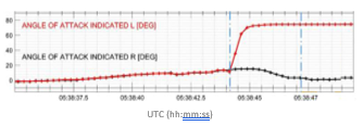 Figure 1: AoA measurements for the Ethiopian Airlines accident [21]
 Figure 2: AoA measurements for the Lion Air accident [22]
The authors of the present paper deem that a suitable customization of the AoA estimator developed for GA aircraft and presented in [1] and [17] could help addressing the issues discussed for Commercial Aviation aircraft. Indeed, it could be exploited as an additional virtual sensor that, coupled with existing physical sensors and suitable voting algorithms [25]-[27], allows to implement a physical-analytical redundant measurement system that is robust to a single fault of the physical sensors. This measurement system could significantly improve the safety of the aircraft, reducing the occurrence of LOC-I related accidents, saving human lives, and avoiding the economic impact on the airliners and the aircraft manufacturers consequent to those accidents. The main benefit of this research to the industry consists in the possibility to achieve this result without the need for hardware modification to the existing aircraft, installation of additional physical sensors or change to the avionics hardware architecture. In fact, the proposed approach just requires the installation of the software code for the computation of the robust angle of attack measurement, which exploits as input the measurements provided only by the sensors already available on-board.
The next sections of the paper detail the proposed approach. The innovative AoA estimator is first described in section 2. Next, a possible application to commercial aviation aircraft is proposed, defining the architecture and the algorithms to implement a robust fault tolerant measurement system. Finally, section 4 shows the performance of the proposed method, assessed in simulation through Monte Carlo analysis. A section of conclusion ends the paper.
2. Angle of Attack Virtual Sensor
The design of the proposed angle of attack estimator was originally based on the following requirements:
- to be applicable to a wide set of aircraft;
- to exploit the information commonly available for GA aircraft;
- the installation of specific additional sensors shall not be required.
These requirements imply that the estimation method shall not require the knowledge of the detailed aerodynamic model, that is specific of each type of aircraft.
The proposed approach works in two steps. First, the parameters of the estimation algorithm are tuned through a calibration procedure, which consists in performing a flight test that shall be executed just once. Next, normal operations are carried out, that is, the estimator could compute the angle of attack during the flight.
The proposed method uses the measurements provided by sensors which are usually exploited for primary navigation and does not need a dedicated angle of attack sensor. It guarantees that the measurement’s accuracy is independent upon the installation of the AoA sensor. It is worthy to note that the same set of sensors is used both for the calibration and in the normal operations. Figure 3 shows the basic concept of the virtual sensor. The following subsections details the calibration procedure and the angle of attack computation.
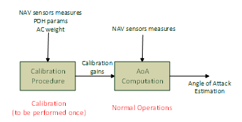 Figure 3: AoA virtual sensor basic concept
2.1. Calibration Procedure
The calibration procedure aims at identifying the lift curve of the aircraft and consists in flying steady and wing leveled at two different airspeed values (set points), which are close to the boundaries of the aircraft flight envelope. The test is repeated for each aircraft configuration that has significantly different aerodynamic characteristics. The calibration requires the knowledge of:
- few parameters available in the POH: MTOW (Maximum Take-off Weight), SEW (Standard Empty Weight), Stall Speed and Maximum Speed in clean and flapped configurations
- aircraft weight (it is worthy to remark that the weight shall be known only during the calibration flight and not during normal operations of the virtual sensor).
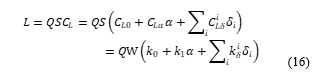
The lift (L) is assumed linear with respect to the angle of attack (α) and to the deflection of the longitudinal aerodynamic surfaces ( ):
![]() where Q is the dynamic pressure, CL is the lift coefficient, S is the aerodynamic reference surface, , and are the lift aerodynamic derivatives. The contribution to the lift of all the longitudinal surfaces deflection is assumed negligible, except for the flaps ( ). Two flap configurations are considered for GA aircraft, clean and full flap. Each configuration has a different lift curve, which is still assumed linear and is uniquely identified by its slope ( ) and intercept (CL0). The calibration procedure is performed for both the configurations, the corresponding aerodynamic derivatives CL0, are computed, and a linear variation for these derivatives is assumed to compute their values for intermediate configurations of the flaps. This approach implies that the values of CL0 and depend on the deflection of the flaps, whereas the explicit dependence in equation (1) of L on could be delated; therefore, the equation (1) could be reformulated as:
where Q is the dynamic pressure, CL is the lift coefficient, S is the aerodynamic reference surface, , and are the lift aerodynamic derivatives. The contribution to the lift of all the longitudinal surfaces deflection is assumed negligible, except for the flaps ( ). Two flap configurations are considered for GA aircraft, clean and full flap. Each configuration has a different lift curve, which is still assumed linear and is uniquely identified by its slope ( ) and intercept (CL0). The calibration procedure is performed for both the configurations, the corresponding aerodynamic derivatives CL0, are computed, and a linear variation for these derivatives is assumed to compute their values for intermediate configurations of the flaps. This approach implies that the values of CL0 and depend on the deflection of the flaps, whereas the explicit dependence in equation (1) of L on could be delated; therefore, the equation (1) could be reformulated as:
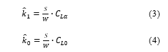
![]() where W is the aircraft weight and the parameters , named calibration gains, are defined as follows (the dependence of CL0, , and on is not shown for the sake of conciseness):
where W is the aircraft weight and the parameters , named calibration gains, are defined as follows (the dependence of CL0, , and on is not shown for the sake of conciseness):
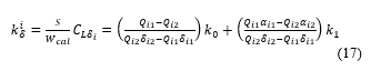
 During the calibration flight, the aircraft weight is denoted as Wcal and the calibration gains (a set for each configuration) are computed as defined in [17]:
 where is the pitch angle. All the variables on the right-hand sides of the above equations represent measurements gathered during the calibration flight and the subscripts 1 and 2 refer to the set point index (two set points for each aircraft configuration). Therefore, the calibration gains could be easily evaluated.
Replacing (5) and (6) in (2) and rearranging, we get the lift equation applicable during normal operations [17]:
 where Wconv is the actual aircraft weight if it is known, otherwise it is a conventional weight given by [17]:
![]() The values of the constants C0 and C1 are computed with the aim to optimize the angle of attack estimation error.
The values of the constants C0 and C1 are computed with the aim to optimize the angle of attack estimation error.
2.2. Angle of Attack Computation
After the completion of the calibration procedure, the virtual sensor can estimate the angle of attack. The estimation algorithm exploits an Extended Kalman Filter (EKF), which combines the knowledge of the lift curve, identified during the calibration, with the measurements get from ADS (air-data system), GPS and IMU. The EKF state vector includes five variables, that is, the angles of attack (α) and sideslip (β) and the wind velocity components (WN, WE, WD), expressed in North-East-Down (NED) reference frame. Classical kinematic equations in polar form [28] describe the dynamics of the aerodynamic angles, whereas stochastic zero-order Gauss-Markov processes [29] are used to represent the wind velocity behavior. These equations are applicable to any type of aircraft [17]:
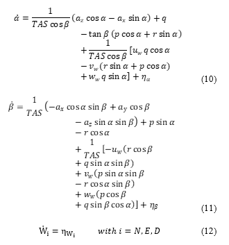 where:
- ax, ay and az are the inertial acceleration components in the body reference frame (provided by the IMU);
- p, q and r are the angular rates components (roll, pitch and yaw rate) in the body reference frame (provided by the IMU);
- TAS is the module of the true air speed (provided by the ADS);
- are process noises, which are assumed zero mean multivariate Gaussian with covariance matrix Qnoise;
- uw, vw and ww are the wind velocity components expressed in the body reference frame and computed as:
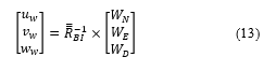 is the Transformation matrix from body axes to NED axes.
The measurement vector is given by the inertial velocity components ( , , in the NED reference frame (provided by the GPS) and the normal load factor (Nz) in body axes (provided by the IMU). The following equations are used [17]:
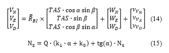
where:
- Nx is the axial load factor;
- are measurement noises, which are assumed zero mean multivariate Gaussian with covariance matrix Rnoise;
- k1 and k0 are the calibration gains.
The last measurement equation holds in the hypotheses of thrust aligned to the X-body axis (that is, with negligible contribution to the normal load factor) and small angle of attack approximation. If a measurement of the current thrust is available, then the contribution along the normal load factor could be added in the equation to remove the approximation. Finally, it is also worthy to note that if the calibration gains k1 and k0 are computed using the conventional weight instead of the actual one, then an approximation is introduced that affects the computation of the right-hand side of the equation (15) and consequently of the angle of attack. The availability of the measurement of the actual weight allows removing this approximation and improving the estimation results.
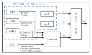 Figure 4: Physical-analytical redundant angle of attack architecture
3. Fault Tolerant Angle of Attack Measurement System for Commercial Aircraft
The proposed angle of attack estimator is applicable to commercial aviation aircraft after a suitable customization. Commercial aircraft are already equipped with one or more (but sometimes less than three [25]) physical angle of attack sensors. Indeed, the angle of attack measurement is nowadays a critical flight parameter as well as other primary navigation measurements. The introduction of a virtual sensor provides an additional and independent measurement, which in conjunction with the physical sensors, allows implementing a single fault tolerant measurement system based on physical-analytical redundancy. Figure 4 shows a possible architecture of the proposed angle of attack measurement system, which exploits two physical sensors of the AoA.
The following subsections detail the customization of the estimator with respect to the one developed for GA aircraft and the voting algorithms applied to compute the consolidated AoA measurement out of the three AoA inputs.
3.1. Virtual Sensor Customization to Commercial Aviation
Some of the assumptions introduced in the design of the estimator for GA application can be removed if the estimator is applied to commercial aircraft.
First, in commercial flight an estimation of the aircraft weight is entered in the aircraft Flight Control Computer (FCC) before each flight, therefore it is a known parameter (although roughly) that can be provided as input to the AoA estimator. The use of a fuel consumption model allows computing the weight variation during the flight execution. Consequently, in the equations (7) and (8) the conventional weight can be replaced by the actual one and equation (9) is not used. Moreover, it is worthy to note that the availability of two physical sensors of the angle of attack allows improving the knowledge of the aircraft weight online while the aircraft is flying. Indeed, when the physical measurements coincide (that means supposedly the physical sensors are working properly), the value of the aircraft weight in the AoA estimation algorithm could be tuned (within a reasonable range) to force the virtual sensor measurement to converge to the physical ones. A suitable strategy can be defined to perform periodically this check and possibly to update the aircraft weight.
Second, commercial aircraft have several control aerodynamic surfaces and their configuration affects the lift curve of the aircraft. The deflection of each of these control surfaces is available to the FCC and it shall be used as an additional input to the AoA estimation algorithm. This consideration implies a modification to the aerodynamic modelling. The lift equation is more complex than the one defined by equation (7). It shall consider the effect of all the relevant aerodynamic surfaces, which in first approximation are assumed having a linear effect (however, quadratic, cubic or in general polynomial effects could be also used). Accordingly, the lift is given by:
 where δi is the deflection of the i-th aerodynamic surface and is an additional calibration gain for each surface (more than one gain could be introduced for each surface if nonlinear effects are considered). Concerning the calibration process, the main differences with respect to the General Aviation aircraft are:
- an increased number of set points during the calibration flight shall be gathered, due to the increased number of calibration gains that shall be computed;
- the measurement of the deflection of each aerodynamic control surface is available and could be used as input to the calibration computation;
- the angle of attack measurement is available during the calibration (provided by the physical sensors), therefore it shall not be replaced by the pitch angle measurement.
The calibration test is performed first gathering two set points at different speeds (close to the aircraft’s envelope limits) in clean configuration. The measurements in these set points allow the computation of the gains k0 and k1 by using equations (5) and (6), in which the angle of attack measurements replace the pitch angle ones. Next, two additional set points are gathered for each aerodynamic surface. These set points are collected again at two different speeds; only the aerodynamic surface related to the gain to be computed is deflected, whereas the deflections of all the other surfaces are null. Each gain is computed through:
 where the subscripts i1 and i2 identify the two set points related to the i-th surface; α, δ and Q are measured and k0 and k1 are already computed at this stage.
The availability of measurements of the actual weight of the aircraft and of the aerodynamic control surfaces deflection allows removing the approximations introduced in the estimator algorithm designed for GA application, leading to a significant improvement of the estimation accuracy.
 Figure 5: Effect of faulty AoA measurement on the airspeed computation [21]
Finally, it is worthy to remark that, during normal operations, the angle of attack computed by the estimator shall be completely independent from the AoA measurements provided by the physical sensors, in order to implement correctly the analytical redundancy. The estimator, as shown in Figure 4, exploits the measurements from GPS, AHRS and ADS sensors. GPS and AHRS are completely independent from the vane sensor. On the other hand, the AoA measured by the vane is usually exploited to correct the raw value of the static pressure measured by the ADS, in order to compensate for errors due to sensor position and aerodynamic effect. The corrected static pressure is then used by the air data computer to calculate the true airspeed, which therefore is influenced by the AoA measured by the vane. The effect of the AoA on the computation of the airspeed is pointed out by the data of the Ethiopian Airlines accident flight. Figure 5, excerpt of [21], shows the computed airspeed based on the static pressure corrected with left and right angle of attack measurements. The erroneous AoA values, provided by the left sensor, produced corrected static pressure values greater than the true ones and consequently the computed airspeed values are lower than the true ones.
The row static pressure values (before applying the correction based on the AoA measurement) from both sides were identical, as shown in Figure 6 [21]. The different static pressure measurements highlighted in Figure 5 were therefore only due to the AoA correction. This effect should be considered in the selection of the inputs to the angle of attack estimation algorithm. Specifically, the uncorrected values of all the air data sensors shall be provided to the estimator. Possibly corrections of these inputs depending on the angle of attack shall be based on the AoA value computed by the estimator itself, at the previous computation time step. This approach guarantees the independence of the measurements provided by the analytical and physical sensors and used as input to the voting algorithm.
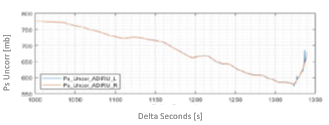 Figure 6: Static pressure reconstruction without AoA correction [21]
3.2. Voting and Signal Validity Check Algorithms
The voting algorithm consists in generating one single angle of attack measurement (consolidated value) out of three input signals of a triplex redundant architecture. Different voting techniques are available in the literature. The proposed approach applies a weighted voting, in which the consolidated signal is computed through a weighted mean of the valid inputs:
 where α is the consolidated value, αi is the i-th measurement, and pi is the i-th weight. Several choices could apply to the definition of the weights. They can be all equal, or a bigger weight could be assigned to the median input [25], or the weights could be all different, based on some metrics or criteria [26]. For each signal we define a weight that is inversely proportional to the supposed precision of the sensor providing the measurement. Assuming the input measurements are affected by a Gaussian error with standard deviation σi, the following weights are used:
![]() where Fi is the validity flag of the i-th measurement, which is null if the input measurement is invalid, otherwise it values 1. To check the validity of each input, the algorithm computes at each time step the difference between the measurements of the angle of attack provided by the available sensors, and for each couple of sensors compares the difference (Dij) with a suitable threshold (Tij):
where Fi is the validity flag of the i-th measurement, which is null if the input measurement is invalid, otherwise it values 1. To check the validity of each input, the algorithm computes at each time step the difference between the measurements of the angle of attack provided by the available sensors, and for each couple of sensors compares the difference (Dij) with a suitable threshold (Tij):
 If both the differences related to the i-th measurement exceed the related thresholds (that is, the above relations involving the signal αi are not satisfied) continuously for a predefined number of samples Ns, the i-th measurement is declared invalid and Fi is set equal to zero. Consequently, the computation of the consolidated value does not use the i-th measurement, because related weight is null. The thresholds are given by:
![]() The values of both the constant Cij and the number of samples Ns used to check conditions (21) to (23) are selected as a trade-off, in order to maximize the capability to detect invalid signals while minimizing the false alarm rate.
The values of both the constant Cij and the number of samples Ns used to check conditions (21) to (23) are selected as a trade-off, in order to maximize the capability to detect invalid signals while minimizing the false alarm rate.
4. Angle of Attack Measurement System Performance
The performance of the proposed measurement system has been assessed in simulation through Monte Carlo analyses. The Monte Carlo technique is a procedure for numerically obtaining an estimation of the statistical characterization (mean, variance, cumulative probability, etc.) of a function’s output. To this end, the input parameters of the function vary independently according to their statistical characterization, and the output of the function is computed for each realization of these inputs. The statistics of the output are then evaluated. Results presented in this section concern the angle of attack estimator (also including the calibration procedure) and the triplex redundant measurement system. A simulation tool was implemented as test harness to execute the analyses.
4.1. Simulation Tool
The simulation tool is implemented in Matlab/Simulink environment and is composed of:
- The main routine, which allows:
- setting up the flight test manoeuver,
- varying the inputs of the Monte Carlo analysis according to their statistical characterization
- computing the performance metrics.
- A simulation model, presented in Figure 7, which includes:
- AC Model – the detailed parametric models for the simulation of the aircraft, the atmosphere (winds and turbulence) and the on-board sensors.
- AP – an autopilot that is able to perform automatically the requested test manoeuver.
- Algorithms Feature – a module implementing the algorithms for the angle of attack estimation.
- Save Results – a module that saves the simulated inputs and computed outputs.
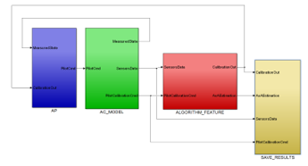 Figure 7: Simulation model for Monte Carlo analyses
- A routine that implements the triplex redundant AoA measurement system and computes the consolidated angle of attack.
The aircraft is modelled using the flight mechanics equations of a six degrees of freedom rigid body [30] and comprises a detailed aerodynamic model, also reproducing the stall phenomenon. The aircraft model has been validated in flight through the CIRA experimental aircraft [31]. The simulation of the relevant atmospheric phenomena is based on the ISA standard atmosphere [30] and the Dryden turbulence model [32]. The atmosphere model includes horizontal constant winds (variable with altitude), three-dimensional turbulence disturbances, and vertical gust (represented through “1-cosine” model) [32]. The three-dimensional turbulence is modelled by applying appropriate forming filters to band-limited white noise; the longitudinal, lateral, and vertical components ( ) of the spectra of these forming filters are given by:
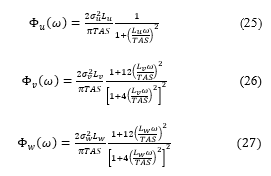 where (Lu, Lv, Lw) and (σu, σv, σw) represent the turbulence scale lengths and intensities, respectively. The vertical gust velocity (Vvg) is computed through:
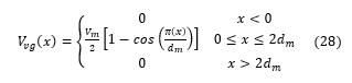 where Vm is the maximum gust magnitude and dm is the gust half-width.
The sensors model simulates actual sensors (ADS, AHRS, GPS) that measure the signals needed by the algorithms under test. The models of the ADS and AHRS compute the measurements of the generic signal (sm) at time tk by adding bias (bs) and Gaussian noise ( ) to the true signal value (st):
![]() A low pass filter is then applied to the signal sm, in order to emulate the sensors dynamics (frequency band limitation). The GPS model also introduces a data latency ( ) in the measurements, which is assumed negligible for the other sensors [33]:
A low pass filter is then applied to the signal sm, in order to emulate the sensors dynamics (frequency band limitation). The GPS model also introduces a data latency ( ) in the measurements, which is assumed negligible for the other sensors [33]:
![]() The data sheets of commercial off the shelf sensors are used to define bias, noise, latency and low pass filter characteristics. The sensors model allows injecting a failure in the measurement, such as additional bias, drift, or data freezing. In the Monte Carlo analyses, this feature was used only to simulate the failure of the angle of attack physical sensors.
The data sheets of commercial off the shelf sensors are used to define bias, noise, latency and low pass filter characteristics. The sensors model allows injecting a failure in the measurement, such as additional bias, drift, or data freezing. In the Monte Carlo analyses, this feature was used only to simulate the failure of the angle of attack physical sensors.
4.2. Monte Carlo Analyses
Three different Monte Carlo analyses were performed to assess the performance of the following functionalities:
- calibration of the AoA estimation algorithm,
- AoA estimation,
- fault tolerant AoA measurement system.
The first two analyses were carried out considering three different classes of GA aircraft (light, medium and heavy airplanes). Indeed, the AoA estimation algorithm and its calibration procedure were originally designed for this category of aircraft. It is worthy to remark that this choice is conservative, because, as explained in the previous sections, improved results are obtained if the AoA estimator is applied to commercial aircraft. In the considered analyses the following parameters of the simulation model varied according to their statistical characterization, in order to obtain an accurate statistical assessment of the algorithms under investigation:
- aircraft weight, centre of gravity and inertia matrix;
- sensors’ measurement error (bias and white noise);
- initial flight conditions;
- atmospheric conditions: horizontal wind (direction between 0 and 360 degrees, intensity up to 20Kts), turbulence (three levels of turbulence intensity), vertical gusts (cosine shape).
Uniform distribution is assumed for all these parameters, in order to get conservative results [34].
The last Monte Carlo analysis assumes the availability of a triplex AoA measurement (two physical sensors plus the AoA estimator) and assesses the performance of the proposed angle of attack measurement system, only considering the angle of attack trajectories and regardless of the aircraft being a GA or a commercial aircraft.
4.3. Performance Assessment Results
The first Monte Carlo analysis allowed getting a statistical characterization of the calibration gains and then of the aircraft lift model. The analysis comprised 1000 simulation runs for each of the considered aircraft classes. The actual aircraft weight, which is required as input to the procedure, was corrupted with a measurement error
![]() where Wm and Wt are measured and true weights, respectively, and is a random noise that varies from one simulation run to the other with uniform distribution in the range [-0.03, 0.03] (that is, the measurement error is in the range ±3% of the true weight). Concerning the model of the atmosphere, the turbulence level varied randomly between 0 and 1. Figure 8 and Figure 9 present the results for one of the considered aircraft categories, showing the estimation of the coefficients CL0 and CLα normalized with respect to their true values, which are known in simulation.
where Wm and Wt are measured and true weights, respectively, and is a random noise that varies from one simulation run to the other with uniform distribution in the range [-0.03, 0.03] (that is, the measurement error is in the range ±3% of the true weight). Concerning the model of the atmosphere, the turbulence level varied randomly between 0 and 1. Figure 8 and Figure 9 present the results for one of the considered aircraft categories, showing the estimation of the coefficients CL0 and CLα normalized with respect to their true values, which are known in simulation.
 Figure 8: Normalized CL0 ceofficient computed in the calibration
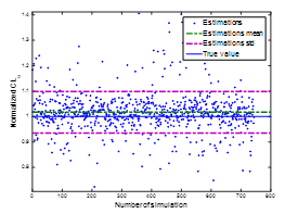 Figure 9: Normalized CLα ceofficient computed in the calibration
Due to the turbulence and to the poor performance of the used autopilot, not all the 1000 calibrations were successful (the success rate was about 75%), that is, the aircraft was not able to keep the required stationary flight condition for a predefined period. The mean error on the CL0 estimation, computed on the successful tests, is about 20%, whereas the mean value of the estimated CLα is very close to its true value. In order to assess the effect of these errors on the AoA estimation, a subset (250 samples) of the calculated couples (CL0, CLα) was used to estimate the angle of attack in the same conditions flown to perform the calibration. The accuracy of the estimation, evaluated as the mean of the root mean square error (RMS), is 0.64 degree.
The second Monte Carlo focused on the AoA estimation. Several typical manoeuvers were considered, such as level flight, turn, climb, descend, stall, stall in sideslip, stall in turn. A dedicated Monte Carlo analysis was performed for each of these manoeuvers. In each run, the calibration gains k1 and k0 were randomly drawn from the results obtained in the calibration Monte Carlo analysis for the same aircraft category. The number of simulations performed in each Monte Carlo Analysis was chosen in order to have a stable root mean square (RMS) error and to get the 95% confidence level on the probability to have the RMS below a given threshold. Indeed, given a condition PX to check (such as, the RMS error is below the threshold), the confidence interval on the satisfaction of the condition can be computed as [35], [36]:
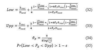 where Ntest is the number of tests performed in the Monte Carlo analysis, ksuc is the number of tests in which the condition PX is satisfied, Pr denotes the probability, and is the fixed confidence parameter ( = 0.05 in our case). Figure 10 and Figure 11 show the trend of RMS mean and standard deviation for one Monte Carlo, used to select the number of runs.
The metrics applied to assess the estimator performance are:
- the mean estimation error (MEE), which represents a measurement of the estimation accuracy in static conditions;
- the root mean square error (RMS), which indicates the overall accuracy of the estimation;
- the correlation between true and estimated angle of attack (CORR), which measures the capability of the estimator to track the dynamic behavior of the true value.
The assessment of the estimator’s performance considers all the error’s sources that are present during operative conditions, including unknown aircraft weight, sensors’ error, and the effect of wind, turbulence and vertical gust. Of course, it produces a degradation of the accuracy with respect to ideal conditions. In level unaccelerated flight, under all possible aircraft configurations and turbulence levels, the MEE is lower than 1.5 degrees. The estimator is able to compute the angle of attack with RMS error varying from about 0.9 degrees for level flight under all possible environmental disturbances to less than 3 degrees for dynamic stall manoeuver, representing the worst-case condition. The average correlation factor between estimated and true angle of attack is bigger than 0.9, confirming the capability to track the dynamics. A sensitivity analysis highlighted that the main source of estimation error is the approximation introduced on the aircraft weight. Indeed, while actual aircraft weight in the simulator randomly varied with uniform distribution within the range [WSEW, WMTOW], the weight used by the estimator is constant in all the simulation runs and is equal to the conventional weight. The value of the conventional weight was selected to get conservative errors when approaching stall, that is, the angle of attack estimation is bigger than its actual value, also at cost of increasing maximum error. This choice derives from the need to anticipate the stall condition. It also allows using optimized algorithms (not described in the present paper) to post process the error when the AoA increases, in order to get very reliable and accurate indication about stall approaching. The knowledge (also rough) of the actual aircraft weight (usually available for commercial aircraft) could significantly improve the estimation performance. Figure 12 presents the estimation of the angle of attack in level flight condition and in presence of a vertical gust, with length equal to 150 meters and maximum amplitude equal to 1600 feet per minute.
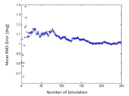 Figure 10: Mean of the RMS error versus number of simulation runs
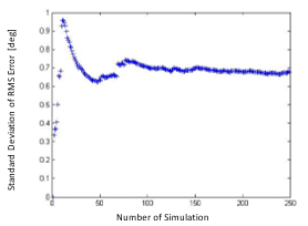 Figure 11: Standard deviation of the RMS error versus number of simulation runs
The final Monte Carlo aimed at assessing the capability of the redundant measurement system to detect a faulty sensor before its effects become significant and dangerous. To this end, one of the physical measurements of the angle of attack is corrupted by injecting one of the following faults, at a given time of the flight:
- constant bias, randomly selected in the range [5, 15] degrees;
- drift with slope randomly selected in the range [0.5, 5] degrees per second;
- signal freezing at a constant value.
The simulation lasts 90 seconds for each run (for the stall manoeuver it can end before 90 seconds if the aircraft stalls). The measurements are sampled at 10 Hz and the fault is injected 10 seconds after the start. The performance of the system is assessed by measuring the error of the consolidated angle of attack (output of the triplex redundant measurement system) with respect to the true angle of attack. Specifically, the mean and the standard deviation of the RMS error are evaluated. Moreover, the percentage of missed fault detections (that is, the percentage of faults that are not detected by the system) and of nuisance alarms (that is, the percentage of declaration of invalid measurement when the fault is not present) are assessed. Monte Carlo analyses are carried out in four different flight conditions: climb, descent, cruise disturbed by a vertical gust, stall. In the first three conditions, the angle of attack is almost stationary; therefore, only bias and drift faults are added to the measurements of one physical AoA sensor (the freezing of the signal does not produce relevant errors). Bias, drift and signal freezing are used in the stall manoeuver, in which the angle of attack varies significantly during the test. All the Monte Carlo analyses are repeated twice. In the first set of analyses, the measurement system does not compensate for the estimation error due to the approximated aircraft weight (due to the use in the estimation of the conventional weight instead of the actual one). Table 1 shows the results for this test case. In the second set of Monte Carlo simulations, the estimated AoA is corrected by removing a constant offset, before providing it as input to the voting algorithm. The offset is computed as the mean difference, on a sufficiently long time, between the estimated AoA and the angle measured by the physical sensors, when these sensors measure about the same values (that means supposedly they are working properly). This procedure allows to compensate for, although roughly, the error due to the approximated weight. Table 2 presents the results for the second set of Monte Carlo analyses, whereas Figure 13 shows the results of one simulation run, in which the aircraft performs a stall manoeuver and one physical sensor of the angle of attack experiences a constant bias fault.
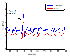 Figure 12: Angle of attack estimations for level flight with vertical gust
Table 1: Results of Monte Carlo analyses for the triplex redundant measurement system (without compensation for unknown aircraft weight)
| Fault | RMS mean [deg] | RMS std [deg] | False alarm % | Missed alarm % | |
| Climb | Bias | 0.67 | 0.18 | 6.4% | 0% |
| Drift | 0.47 | 0.15 | 7.2% | 0% | |
| None | 0.24 | 0.09 | 1.6% | 0% | |
| Descent | Bias | 0.68 | 0.19 | 0.8% | 0% |
| Drift | 0.48 | 0.16 | 0.8% | 0% | |
| None | 0.23 | 0.08 | 0.4% | 0% | |
| Cruise | Bias | 0.70 | 0.17 | 4.8% | 0% |
| Drift | 0.49 | 0.16 | 4.0% | 0% | |
| None | 0.24 | 0.09 | 0% | 0% | |
| Stall | Bias | 1.34 | 1.00 | 22.4% | 5.6% |
| Drift | 1.08 | 1.11 | 26.4% | 0% | |
| Freeze | 1.08 | 1.06 | 28.8% | 0% | |
| None | 0.26 | 0.08 | 13.6% | 0% |
Table 2: Results of Monte Carlo analyses for the triplex redundant measurement system (with compensation for unknown aircraft weight)
| Fault | RMS mean [deg] | RMS std [deg] | False alarm % | Missed alarm % | |
| Climb | Bias | 0.62 | 0.16 | 0% | 0% |
| Drift | 0.39 | 0.09 | 0% | 0% | |
| None | 0.20 | 0.06 | 0% | 0% | |
| Descent | Bias | 0.63 | 0.16 | 0% | 0% |
| Drift | 0.40 | 0.08 | 0% | 0% | |
| None | 0.20 | 0.06 | 0% | 0% | |
| Cruise | Bias | 0.64 | 0.15 | 0% | 0% |
| Drift | 0.40 | 0.08 | 0% | 0% | |
| None | 0.20 | 0.06 | 0% | 0% | |
| Stall | Bias | 0.89 | 0.30 | 1.6% | 0% |
| Drift | 0.63 | 0.22 | 2.4% | 0% | |
| Freeze | 0.73 | 0.23 | 2.8% | 2.8% | |
| None | 0.21 | 0.04 | 1.2% | 0% |
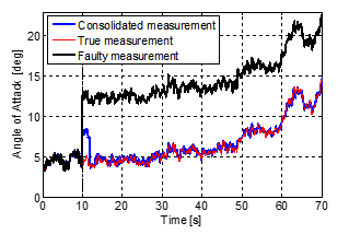 Figure 13: Angle of attack measurement for a stall manoeuver and a constant bias fault on one physical sensor
The improvements due to the weight error compensation are significant in all the examined metrics. As expected, a better estimation of the angle of attack leads to a reduction of the RMS error on the consolidated measurement and to a more effective detection of the faulty sensor. For all the considered flight phases and fault types, the mean RMS error is far below 1 degree also when the fault is present. The false alarm rate is always null, except for the stall maneuver in which however it is very low. The measurement system is able to detect all the injected faults, except for the case of measurement freezing, in which only 7 cases on 250 are missed (2.8%). Although these results are already very good, an optimization of the parameters of the voting and signal validity check algorithms could improve the result for both false and missed alarm percentage. Further investigations will be dedicated to this issue in the future.
5. Conclusion
This paper presented an original angle of attack measurement system applicable to commercial aviation aircraft. The system is based on a triplex physical-analytical redundancy, which only requires two physical sensors of the angle of attack. Indeed, the third sensor is virtual; it is an innovative angle of attack estimator, originally developed to provide General Aviation pilots with a maintenance free and low cost but accurate indication of trend toward stall and stall margin. This estimator does not require any angle of attack dedicated sensor, neither detailed information about the aerodynamics of the specific aircraft, which is identified during a short calibration flight, carried out just once. The customization of the virtual sensor for the application to commercial aircraft, described in the present paper, allows getting better performance, due to the possibility to exploit additional information (such as, aircraft weight and deflection of the aerodynamic control surfaces), which usually are not available to General Aviation aircraft.
The physical-analytical redundant architecture defined in this paper provides a measurement system which is robust to a single fault of the angle of attack sensors. It could significantly improve the safety of the aircraft, reducing the occurrence of LOC-I related accidents, saving human lives, and avoiding the economic impact consequent to those accidents. It has the peculiarity to be applicable to the existing commercial aircraft by installing just a software code that implements the proposed algorithms, without the need to modify the on-board avionics instrumentation.
The performance of the proposed measurement system was assessed through Monte Carlo simulations. To this end, a high-fidelity simulation environment was implemented, which includes the models of aircraft, atmosphere, on-board sensors and an autopilot. The simulations highlighted very interesting results of both the angle of attack estimator and the overall measurement system. The latter is able to provide a consolidated angle of attack measurement with a mean RMS error far below 1 degree, also when a fault is present. Concerning the detection of the faults, it is generally successful; both missed and false alarm percentages are close to zero for all the examined cases. An optimized tuning of the proposed algorithms will probably further improve these results.
Future works will be focused on the validation of the system through real-time simulations and in-flight trials.
- A. Vitale, F. Corraro, N. Genito, L. Garbarino, L. Verde, “Innovative Real Time Estimator for Redundancy of Angle of Attack Sensors in Commercial Aircraft,” in Proc. 4th Conference on Control and Fault Tolerant Systems SYSTOL’19, 2019, doi: 10.1109/SYSTOL.2019.8864783.
- General Aviation Joint Steering Committee – Loss of Control Working Groups, Final Report, 2014.
- M. Bromfield, B. Dillman, “The Effects of Using an Angle of Attack System on Pilot Performance and Workload during Selected Phases of Flight,” Procedia Manufacturing, 3, 3222-3229, 2015, doi: 10.1016/j.promfg.2015.07.873.
- ICAO, “Manual on aeroplane upset prevention and recovery training,” Doc 10011, 2014.
- C. Ramprasadh, H. Arya, “Multi-stage fusion algorithm for estimation of aerodynamic angles in mini aerial vehicle,” in Proc. 49th AIAA Aerospace Science Meeting, 2011, doi: 10.2514/1.C031322.
- A. Cho, Y.S. Kang, B.J. Park, and C.S. Yoo, “Airflow angle and wind estimation using GPS/INS navigation data and airspeed,” in Proc. 13th Int. Conf. Control, Automation and Systems (ICCAS), 2013, doi: 10.1109/ICCAS.2013.6704159.
- S. Leutenegger, A. Melzer, K. Alexis, and R. Siegwart, “Robust state estimation for small unmanned airplanes,” in Proc. IEEE Int. Conf. Control Applications, Antibes, France, 2014, doi: 10.1109/CCA.2014.6981466.
- T.A. Johansen, A. Cristofaro, K. Sorensen, J.M. Hansen, T.I. Fossen, “On estimation of wind velocity angle-of-attack and sideslip angle of small UAVs using standard sensors,” in Proc. 2015 International Conference on Unmanned Aircraft Systems (ICUAS), 2015, doi: 10.1109/ICUAS.2015.7152330.
- A. Wenz, T.A. Johansen and A. Cristofaro, “Combining model-free and model-based angle of attack estimation for small fixed-wing UAVs using a standard sensor suite,” 2016 International Conference on Unmanned Aircraft Systems (ICUAS), 2016, doi: 10.1109/ICUAS.2016.7502583.
- H. Long and S. Song, “Method of estimating angle-of-attack and sideslip angle based on data fusion,” in Proc. International Conference on Intelligent Computation Technology and Automation, 2009.
- M. Shaqura, C. Claudel, “A hybrid system approach to airspeed, angle of attack and sideslip estimation in Unmanned Aerial Vehicles,” in International Confonference on Unmanned Aircraft Systems ICUAS 2015, 2015, doi: 10.1109/ICUAS.2015.7152355.
- R.D. Colgren, “Method and system for estimation and correction of angle-of-attack and sideslip angle from acceleration measurements,” U.S. Patent 6273370, November 1, 1999.
- Ramprasadh, S. Prem, L. Sankaralingam, Parag Deshpande, Ravi Dodamani, Suraj C S, “A Simple Method for Estimation of Angle of Attack,” IFAC-PapersOnLine, 51 (1), 353-358, 2018, doi: 10.1016/j.ifacol.2018.05.048.
- P.A. Samara, G.N. Fouskitakis, J.S. Sakellariou, S. Fassois, “Aircraft angle-of-attack virtual sensor design via a functional pooling narx methodology,” European Control Conference ECC2003, 2003, doi: 10.23919/ECC.2003.7085229.
- A. Lerro, M. Battipede, P. Gili, A. Brandl, “Survey on a Neural Network for Non Linear Estimation of Aerodynamic Angles,” in Intelligent Systems Conference, 2017, doi: 10.1109/IntelliSys.2017.8324240.
- A. Lerro, M. Battipede, P. Gili, A. Brandl, “Aerodynamic angle estimation: comparison between numerical results and operative environment data,” CEAS Aeronautical Journal, 11, 249–262, 2020, doi:10.1007/s13272-019-00417-x
- N. Genito, F. Corraro, L. Garbarino, A. Vitale, E. De Lellis, D. Bibby, S. Rieb, K. Jones, “System and method for angle of attack indication with no dedicated sensors and aircraft information,” Patent WO 2016 / 164624, https://patents.google.com/patent/WO2016164624A1/en, October 13, 2016.
- IATA, “Loss of Control In-Flight Accident Analysis Report, 2019 edition,” ISBN 978-92-9264-002-6, 2019.
- Aircraft Accident Investigation Bureau (AIB), “Aircraft Accident Investigation Preliminary Report – Ethiopian Airlines Group – B737-8 (MAX) Registered ET-AVJ – 28 NM South East of Addis Ababa, Bole International Airport – March 10, 2019,” Report No. AI-01/19, 2019.
- Komite Nasional Keselamatan Transportasi, “Aircraft Accident Investigation Report – PT. Lion Mentari Airlines – Boeing 737-8 (MAX); PK-LQP – Tanjung Karawang, West Java – Republic of Indonesia – 29 October 2018,” 2018.
- The Federal Democratic Republic of Ethiopia, Ministry of Transport, Aircraft Accident Investigation Bureau “Interim Investigation Report on Accident to the B737-8 (MAX) Registered ET-AVJ operated by Ethiopian Airlines on 10 March 2019,” Report No. AI-01/19, 09 March, 2020.
- FINAL KNKT.18.10.35.04, “Aircraft Accident Investigation Report,” PT. Lion Mentari Airlines, Boeing 737-8 (MAX), PK-LQP, Tanjung Karawang, West Java Republic of Indonesia, 29 October 2018.
- Bureau d’Enquêtes et d’Analyses pour la sécurité de l’aviation civile, “Report – Accident on 27 November 2008 off the coast of Canet-Plage (66) to the Airbus A320-232 registered D-AXLA operated by XL Airways Germany,” 2010.
- German Federal Bureau of Aircraft Accident Investigation (BFU), “Interim Report,” BFU 6X014-14, 2015.
- D. Ossmann, H.D. Joos, P. Goupil, “Enhanced Sensor Monitoring to Maintain Optimal Aircraft Handling in Case of Faults,” Journal of Guidance, Control, and Dynamics, 40(12), 3127-3137, 2017, doi: 10.2514/1.G002341.
- D. Berdjag, J. Cieslak and A. Zolghadri, “Fault detection and isolation of aircraft air data/inertial system,” Progress in Flight Dynamics, GNC, and Avionics, 6, 317-332, 2013, doi: 10.1051/eucass/201306317
- C. Seren, P. Ezerzer, G. Hardier, “Model-based techniques for virtual sensing of longitudinal flight parameters,” Int. Journal of Applied Mathematics and Computer Science, 25(1), 23-38, 2015, doi: 10.1515/amcs-2015-0002.
- R. E. Maine, K. W. Iliff, “Application of Parameter Estimation to Aircraft Stability and Control,” NASA-RP-1168, June 1986.
- A. Gelb, Applied Optimal Estimation, M.I.T. Press, ISBN 0-262-20027-9, Cambridge, Massachusetts, 1989.
- B. Etkin, Dynamics of Atmospheric Flight, John Wiley & Sons, 1972.
- A. Fedele, N. Genito, A. Vitale, L. Garbarino, “Experimental aircraft system identification from flight data: Procedures and Results,” CEAS 2013 Air & Space Conference, 2013.
- MIL-STD-1797A, “Flying Qualities of Piloted Aircraft,” 1990.
- L. Garbarino, N. Genito, V. Baraniello, E. De Lellis, and A. Vitale, “Low Cost Air Data System For UAV In-Flight Experimentation,” Society of Flight Test Engineers – 23rd European Chapter Symposium, 2012.
- B.R. Barmish, C.M. Lagoa, “The Uniform Distribution: A Rigorous Justification for its use in Robustness Analysis,” Mathematics of Control, Signals, and Systems, 10, 203-222, 1997, doi: 10.1007/BF01211503.
- R. Tempo, G. Calafiore, F. Dabbene, Randomized Algorithms for Analysis and Control of Uncertain Systems, Springer-Verlag, New York, 2005.
- X. Chen, K. Zhou, J.L. Aravena, “Fast Universal Algorithms for Robustness Analysis,” in Proceeding of the 42nd Conference on Decision and Control, 2003, doi: 10.1109/CDC.2003.1272897.