Novel Infrastructure Platform for a Flexible and Convertible Manufacturing

Adv. Sci. Technol. Eng. Syst. J. 6(1), 356–368 (2021);
 DOI: 10.25046/aj060141
Sales behavior and the technical development of products influence their fabrication. As market influences become increasingly volatile and unpredictable, factories will have to adapt their manufacturing to market trends even more in the future. Adaptation is referred to as convertibility and can be achieved, among other things, by mobile and intercompatible machines. Enabling machines to be mobile, its power supply must be wireless and it should be possible to locate it on the shop floor at any time. With the help of the infrastructure platform Intelligent Floor, machines in future factories can be made more mobile than they are today. In combination with the novel autonomous guided vehicle BoxAGV, the platform offers a cost-efficient and highly flexible solution for in-house transport tasks. The transport of goods can be performed based on lot size one and thereby opens a wide field in logistics automation. This paper is an extension of work originally presented in MELECON 2020 and describes the concept and the functionality of the open platform that is implemented so far. It shows how to apply the platform to a real industrial manufacturing environment and highlights the resulting manufacturing benefits. Finally, the next development steps on the platform and machine side are presented.
1. Introduction
These statements are verified in section 2 by using the automobile production as an example. Adapting today’s productions to the new requirements, the Intelligent Floor (IF) poses as a universal platform for the building infrastructure and helps to achieve a flexible and convertible production. The IF is a raised floor that is currently under development. It is designed as a modular floor with individual panel elements that have sensor and actuator functionalities. The V0.5.x prototype can already supply production equipment by wireless power and measures the weight of objects on the floor panel. Furthermore, the IF has an Light Emitting Diodes (LED) display system in each panel included that is built-up with four LED stripes and located in a cross shape on the top of one panel.
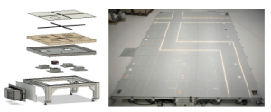
Figure 1: Exploded view of the IF and the prototype V0.5.2 test set-up, which has a size of 10m×7m (L×W). When the picture was taken, as an example a walking path in the production was reproduced by the IF.
The IF consists of the four main components substructure, control and power unit, module inserts and panel (Figure 1). It receives its sensor and actuator capabilities from the module inserts or individually configurable panels. The IF basic version is already equipped with a detection and display functionality. Due to the modular design as a raised floor, the flexible positioning of machines on the IF is made possible through an omnipresent media supply. The IF can generate advantages for users and operators of production facilities that would not be achievable with conventional solutions. Two prototypes of the IF are currently being tested in the ARENA2036[1] using specific use cases of the convertible production.
A first prototype V0.1.1 of the novel Autonomous Guided Vehicle (AGV), hereafter named BoxAGV and shown in Figure 2. It is based on a simple frame construction made of aluminum profiles, to which four meccanum wheels are attached. The four drive motors are connected each to an inverter that receive their commands from the controller in real-time. The BoxAGV has installed a camera for identifying the route, which is mounted centrally in the frame. By using the Wireless Power Transfer (WPT) the battery of the vehicle can be charged dynamically. The entire vehicle technique is embedded in a standard box [1] made of polypropylene with the outer dimension 600mm×400mm×213mm (L×W×H). It offers after its integration still 50% of the origin transport volume.
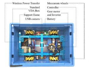
Figure 2: Design of the first BoxAGV prototype V0.1.1, where frame, driving and control components are built-in a standard VDA box.
The combination of IF and BoxAGV meets the requirements of convertible production in terms of logistics flexibility and usability better than the solutions known so far. To verify this hypothesis, a study has been started in the ARENA2036. Using a 70m2 large-scale demonstrator of the IF that interacts with two BoxAGV prototypes, highlights the expected gains for future logistics systems. To initiate a technical discourse, the novel concept is therefore introduced in this paper and evaluated based on a real field application. Additional to the logistic applications, further use cases of the IF are outlined and the importance of WPT for mobile applications is analyzed in more detail.
2. Convertible Production
To understand the purpose of the IF and its benefits for the users, it is essential to get to know more about convertible production. Scientists, in particular the production technology institutes of the University of Stuttgart, have been researching the subject of convertible production since more than 25 years, e.g. [2]–[7]. One of the central findings of their research work, carried out so far, is that in response to the fast changing requirements of the global market, production equipment must be designed to be more modular, mobile and compatible with each other. This is a fundamental of the future factories production concept. To implement this concept is necessary in order to be able of continuing producing economically with a high value-added share. Taking the automotive industry as an example, it will be outlined which factors drive the change in requirements and what kind of solutions can be helpful.
2.1 Driving Factors
The requirement to transform existing production systems to convertible production systems will be illustrated based on two general market developments. These market developments are described using the automotive industry as an example. Based on the research study [8], the number of registered automobile models has increased by 349% between 1990 and 2014 in Germany. In addition, the number of possible equipment options increased with the model variants, so that today almost every new car allows several hundred million of configuration options and is consequently built as a one-off. The second market trend is the shortening of a model’s life cycle. While the life cycle of a Volkswagen Golf 1 was nine years in 1983, it has been reduced to just four years in 2012 [9]. These two market movements are critical not only for the automaker, but also for all their suppliers, who must adapt their products and production facilities to market developments.
The driving force behind the increase in the number of variants and the reduction in product lifecycle times is the interaction between the market and suppliers. The customer’s desire for choice and product individualization is matched by a large number of competing manufacturers who expect to gain sales advantages by offering variants ever faster. The ongoing connection of people through the Internet means that the market and suppliers are better connected than before. This means that a reduction in the number of variants and an extension of the life cycle time cannot be expected in future. Therefore, it is necessary for product makers to adapt their production concepts to the actual situation and to move to convertible production concepts [10, 11]. Here it is important to couple the product life cycle with the life cycle of the production machine. Thus, the rigid coupling of product and machine is not critical if the period of the product life cycle is equal to or longer than the life cycle of the machine. However, the case in which the life cycle of a product is much shorter than that of a machine is critical for automated manufacturing. This causes production difficulties: Machines can no longer be planned, built and commissioned as quickly as the product life cycle requires. As shown in Figure 3, it is therefore necessary to implement a system that synchronizes both life cycles. This synchronization is the main task of the convertible production, as shown by the example in subsection 2.3.
2.2 Solution
There are many possible solutions for synchronizing product and machine life cycles. Two solutions will be highlighted in this paper: Transparency in the production process and faster product changeovers. Transparency is understood as the knowledge of the current position and status of all objects in the production process. Especially with knowledge of the material positions, the flow of goods can be optimized and non-production-related idle times can be reduced or eliminated. By shortening production time, more products can be produced in the same time period. As a result, the proportion of production costs allocated to the product becomes smaller, enabling the product to be produced cheaper. A solution to manage the increase in the speed of product changeovers is the use of modular, manufacturer independent and compatible production equipment. In some cases, solutions for defined manufacturing steps already exist, as it can be shown in the next subsection 2.3.

Figure 3: Product and machine lifecycle coupled by the convertible production.
2.3 Example
The relationship between product and machine life cycle is to be demonstrated using the example of wire harness production. In this case, the product is a wire harness (Figure 4). A wire harness is composed of different wires of various lengths and with a range of wire terminations. The use of wire harnesses is particularly widespread in the automotive industry. For example, an average equipped Volkswagen Golf 7 has a wiring harness with almost 1,000 different wires of a total length around 1.6km and weighing up to 60kg [12]. Each individual wire must be prepared individually for installation in the car. Due to the high demand quantities in the automotive industry, this requires a fully automatic machine that cuts wires to length, marks, strips and terminates them with a connector. Figure 5 shows a wire processing machine, type Zeta 640/650 that is manufactured by Komax. The machine is able to prepare up to 36 different wires with a cross-section from 0.22 to 6mm2 [13].
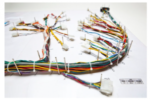
Figure 4: Wire harnesses are used in various industries, like in the consumer industry for wiring household appliances. One of its main advantages is the significantly reduced assembly time compared to single wire installation. Photo: TES.
Today, wiring harnesses take into account the vehicle equipment features ordered by the customer and they are built-to-order. This is done in order to reduce the overall vehicle weight and thus also reduce fuel consumption and exhaust emissions. Such a production strategy leads to a large number of theoretical combinations, which [12] puts at 425 billion. Due to the high variance of the wire harness design as a result of changing vehicle equipment options and cyclical model changes, the wire processing machine is modular in itself. For example, there are up to 13 process modules for the model shown, which take over the feeding of different sized ferrules or the wire labeling. This enables the machine operator to react quickly to product changes. With the help of the modular machine design strategy, the fast-moving product cycle is coupled with the long-lasting machine cycle.

Figure 5: Wire processing machine for the fully automatic production of prepared wires for the use in wire harnesses. Photo: Komax.

Figure 6: The photo shows a wire harness production facility where workers assemble prefabricated wires into a wire harness. Photo: OWC.
Looking at the subsequent production process of the wire harness manufacturing, it is obvious that the fully automatic wire preparation is followed by a completely manual production process. As shown in Figure 6, the prepared wires are now assembled by hand on a pin board to form a complete wire harness. So far, it has not been possible to build a machine for the automatic production of wire harnesses with a development and construction time that is shorter than the product life of a wire harness. Alternatively, it would also be possible to build a modular machine or a combination of individual system modules that are capable of producing complex wire harness layouts automatically. However, this has not yet been achieved either. Thus, product and machine life cycles for wire harness manufacturing in the automotive industry are not synchronized by machines, but manually by workers as shown in Figure 6.
The example of wire harness production can also be applied to other production processes in and outside of the automotive sector. It highlights the demands made on the machine life cycle in terms of flexibility, modularity and degree of automation.
At the same time, fully automatic machines should also be durable and robust investment assets that must guarantee a high output over their life cycle. Therefore, it is necessary to readjust the balance between product and machine life cycle by using new processes and elements from the field of convertible production. The IF described below is a new element from the field of convertible production. It uses an example from intralogistics to show how product and machine life cycles can be synchronized with each other based on machines.
3. Intelligent Floor
The Figure 7 shows a test surface of the IF prototype V0.5.1, which consists of 12 identically constructed panels, their control and power units and its substructure. In addition to the IF basic functionality of visualization and detection, a WPT unit is built into each panel. One panel has a surface area of 1m×1m and a thickness of 46mm.The IF is constructed as a modular raised floor, which is adjustable in its height. In this specific case, the IF has a total height of 40cm. The prototype V0.5.x is designed to carry static loads of min. 1,500 kg/m2. A special feature of the IF is the interconnection of the energy units to form a DC24V grid. This enables higher power to be provided at single points within the grid than could normally be provided by just the power supply unit of each panel. Furthermore, each panel has a control unit for processing its sensors and actuators. The Panel Controller (P-CTRL) is the central element of the control unit and communicates with the higher-level control system, the Section Controller (S-CTRL), over the 100Mbps Ethernet network. The S-CTRL itself manages by definition up to 256 panels. It can be implemented as a physically present controller or a cloud-based solution. Neighboring sections can be combined to a cluster, where the Cluster Controller (C-CTRL) is software-based controller. The IF prototype V0.5.x panels are already hot-plug capable and have the following sensor/actuator capabilities:
- The sensor system for object detection, which is based on load cells, is integrated into the substructure of the IF. Each load cell can measure up to 1,000 kg. Since each stand of the floor is equipped with a load cell, a network of weight values is built up over the area, which enables object detection with a positional accuracy of approx. 0.5m.
- The panel’s surface is divided into four quadrants by LED stripes consisting each of up to 144 LED/m. The LEDs are controlled individually, in groups or all together in color and brightness by the P-CTRL.
- The IF contains up to four module slots, where Figure 7 shows one with a DC24V/240W WPT unit equipped module slot. In the IF prototype V0.5.2, the module slots contain further functionalities. For example, there are installed an e-paper display modul, a radio-based object localisation module and a power socket to provide three-phase current AC400V/16A instead of the WPT unit.
- Depending on the application, it may be useful to combine other functions in addition to the basic functions. This can be done in one panel or over a certain panel area. As the example in Figure 11 shows, the visualization functionality and the WPT unit were used here to charge a BoxAGV.

Figure 7: Prototype V0.5.1 of the IF, which was setup for test purposes in the
ARENA2036. It is assembled from 12 equal panels, each using one module slot for functionality expansion. The module is a 240W WPT unit. Further, all stands are equipped with load cells, measuring the loads applied to the floor continuously.
3.1 Localization
The object localization in prototypes V0.2 and V0.5 is realized with the help of bending beam load cells, which are mounted under each stand of the substructure. During a measurement process, the weight force acts on the bending beam and generates an elastic deformation. This strain is converted into an electrical signal by the four strain gauges glued to the bending beam. In order to convert the signal into a weight value, the strain gauges are connected in a Wheatstone bridge and are made available to the P-CTRL by a subsequent measuring amplifier with an analog-to-digital converter. The controller forwards the weight values to a database located in the S-CTRL over the Ethernet network at intervals of 1 second. The database is designed as a ring buffer with a storage capacity of 256 panels, equal to one section, and a buffer time of 60min. This allows the access to a total of 921,600 weight values.
In order to detect static or moving objects on the IF, the weight values of a time point that are above a defined threshold are extracted from the database. Since the position of the load cells is fixed and each weight value can be uniquely assigned to a load cell, it is possible to detect moving objects. The weight value itself can serve as an indicator of which type of object is being detected. For example, a measured value of 50 to 120kg is an indication of a human being. Object detection can be further refined by comparing the change in weight of several neighboring panels. If the weight sensors of panel A measure the mass m at time t0 and the weight sensors of panel B , which lies next to panel A , measure the mass m at time t1 > t0, it can be assumed that an object with mass m moves in time t1 − t0. Since the distance s between the panels A and B is known due to the uniform structure, the velocity v of the object is known as well. This is useful as another indicator of object types. For example, people in production areas typically move at speeds between 0.8 and 1.6m/s. The object detection gains reliability if weight and velocity values are now combined.
Another possibility of object localization is currently being implemented in a panel of the IF prototype V0.5.2. With the help of a film-based sensor technology that is installed directly under the floor surface, the measuring accuracy and robustness is evaluated. Thus, the substructure of the IF’s next prototype will be simplified and made ready for further applications outside industrial use.
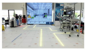
Figure 8: The prototype V0.2.1 uses the LED visualization system to show a walkway on the production area and serves as orientation for visitors. In the top left corner of the photo, an area with mobile production equipment can be seen. A red no-entry zone visually warns visitors that they are not allowed to enter this area.
3.2 Visualization
In the prototype V0.2.1, LED stripes with an LED density of 144 LED/m are installed. Thus, a pixel density of 284 px/m2 is achieved. In the panels of the prototypes V0.5.x, the pixel density has been reduced to 116 px/m2, which is sufficient for information purposes and for steering the BoxAGV. Each LED is from type WS2812B and can be controlled in its color and brightness by the P-CTRL. One LED stripe is embedded in an aluminum profile, on which a translucent cover protects the LEDs. They are wired to a connection box for the data and power supply from the P-CTRL and the DC5V source. In version V0.5.x, the panel is connected via cable to the control and power supply. This connection will no longer be necessary in the following prototype generation to ensure a fast and ergonomic change of the panels.
Since the LED visualization system is mounted on the panel in a cross shape, a chessboard-like grid is created on the surface when several panels are installed. Static dot and line patterns, but also dynamic patterns can be displayed in this grid. Thereby the synchronous visualization is performed by the S-CTRL, which updates all P-CTRLs connected to the section at the same time. As shown in Figure 8, the visualization system enables man/machine and inter-machine communication easily. For example, dynamic LED markings can replace static adhesive tape markings for indicating temporary storage locations for materials. As well it can be used as a guidance system for workers to find other persons or specific objects. Instead of separate ANDON displays, production states can be visualized to the worker on the IF. Moreover, it can also be used for zone identification and in combination with a secure object detection, for safeguarding hazardous areas in production environments. This application example is described in more detail in the subsection 3.4.
3.3 Wireless Power Transfer
Convertible production demands high standards for the mobility of production equipment. To ensure mobility, machines must be freely positionable on the shop floor. Today’s usual cable- and tube-based media supply of machines is contrary to the mobility requirements of convertible production. Therefore, the use of WPT systems is promising. The WPT primary units shown in Figure 9 transmit up to 240W unidirectionally to a static, machine-side secondary unit.
The voltage level is DC24V on both WPT sides. The efficiency achievable during energy transfer is 91% over an air gap of 5mm. As the technical data indicate, the WPT system shown is provided for low-power applications. For example, a workshop cart with electrical label printer was equipped with a secondary side, in order to operate the printer on each charging point of the IF. In addition to the low-power system, a mid-power system is available, whose transfer power is 1,000W with an efficiency of 90% and a transfer distance of up to 10mm. Also a high-power system is already in the prototype V0.5.2 in operation. It is able to transfer a power of 3kW at a distance of 15 to 40mm. Its max. lateral offset of 40mm from the centers of both coils helps to charge machines easily. The IF panel’s design allows to operate up to four WPT units, so that in theory an energy density of max. 12kW/m2 can be achieved.
However, since mobile and thus lightweight production equipment is required for convertible production in particular, the required electrical power is usually rather low. As described in [14], power densities of less than 4kW/m2 are enough for most applications. Fixed and semi-fixed production equipment with a higher power demand, can be supplied using conventional socket units in the raised floor system. One of the most significant challenges of convertible production is the location-independent and dynamically adaptable energy supply of the production equipment. Unfortunately, this challenge can only be solved to a limited extent with the industrial WPT systems on the market today. Therefore, the Institute of Electrical Energy Conversion (IEW) of the University of Stuttgart is researching on the following three fields of WPT:
Dynamic Charging Looking at the operation of industrial WPT systems, it is remarkable that most of them are designed for static coupling of primary (Tx) and secondary (Rx) units – so defined 0Dsystems. Even small deviations in x− or y−direction from the ideal position of the Rx unit in relation to the Tx unit will reduce the transfer power and efficiency. Therefore, only WPT systems capable to couple Rx and Tx units at least along a route (1Dsystems) are suitable for the use in the convertible production environment. Even more appropriate would be a 1.5 or 2Dsystem. The Table 1 summarizes the coupling of Tx and Rx units in x− or y−direction. A solution further developed by [15] is the introduction of separately switchable Tx modules in a grid-like structure that are able to operate as 1.5Dsystem or better, but without having the disadvantages of today’s solutions.
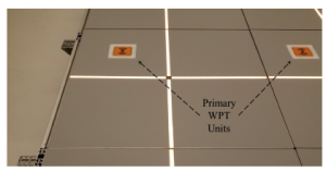
Figure 9: Two low-power Tx units each installed in an IF prototype V0.5.1 panel.
The distance between the units is 1m. Both Tx and Rx units have a uniform size of 100mm×100mm×47mm (L×W×H) and can supply on Rx side 10A at DC24V.
Table 1: Five categories of coupling between Tx and Rx coils in x and y planar movements without angular misalignment of the coil planes.
| Cat. | Figure | Description |
| 0D | The Tx and Rx are statically coupled, so that the two coils must be exactly aligned with each other. | |
| 0.5D | The Tx and Rx are statically coupled, but with a tolerance δ in two dimensions. | |
| 1D | The Rx side has one degree of freedom and is static in the second in relationship to the Tx side. | |
| 1.5D | The Rx is movable in one dimension and static with a tolerance δ in the second dimension. | |
| 2D | The Rx is completely dynamic in both dimensions, so that the Rx can be placed anywhere in relationship to the Tx device. |
Bidirectional Power Transfer Moreover, the industrial WPT systems available on the market are characterized by their unidirectional power transfer. Bidirectional systems are not yet available on the market. However, bidirectional energy transfer would have many advantages in the environment of convertible production. For example, battery-buffered machines could help to compensate peak loads in production by feeding energy into the IF’s DC grid via the bidirectional WPT system. At low-load times, the batteries can be recharged, which results in cost advantages for the operator in terms of a homogenized energy demand of his production [16, 17].
Power Density A so far unknown key figure is the power density needed to operate mobile machines in the environment of convertible production. This figure depends on the machines used and cannot be given as a general rule. However, with the operation of the prototypes V0.2.1 and V0.5.x, first empirical values are emerging which indicate a certain range. Measurements on lightweight mobile assembly and transport machines, showed a power requirement of less than 3.7kVA per feeding point. For all equipment used in the ARENA2036 test environment, a power input of 11kVA was sufficient. In [18], the author calculates that the power requirement of an AGV with 500kg payload is 347W during steady driving. According to [14], a continuous power output density of 500 W/m2 is sufficient to start the supply of mobile production equipment.
3.4 Use Case ’Safety Zone’
Beside the intralogistics use case of the BoxAGV, which is described in more detail in subsection 3.5, another IF application shall be presented briefly. With the help of the safety panels a safety zone can be marked by the LED system and monitored for unauthorized entry of persons or mobile machines. To protect humans from injuries caused by dangerous movements of machines, such movements must be encapsulated according to ISO13857 or limited in force and torque to non-hazardous values according to ISO/TS15066. For this reason, protective fences as enclosures, sensors for initiating emergency stops or robots suitable for man-machine operation are used today, among other things. Especially the enclosures are static in their nature and thus in conflict with the goals of the convertible production. The safety zone application described below was implemented on the IF prototype V0.2.1 and shows the potentials as well as the added value for the user and operator of the IF. The application classifies two types of safety zones:
Immobile machinery The safety zone around a production facility is normally realized with a fence and its access is monitored by safety devices triggering an emergency stop. To enable the access of persons and machines into hazardous areas, these entrances, e.g. doors and rolling gates, are secured with safety locks or safety light curtains. As well as for the safety enclosure of the production equipment and for access supervision in the safety zone, engineering time and capital expenditure must be considered. In the end, the solution remains inflexible with regard to the convertible production, because a relocation of the production facility always means a fully relocation of the safety enclosure. Considering the extensive mechanical and electrical installation of the safety equipment as well as the necessary acceptance test of the safety system, production managers usually decide against relocating machines despite more advantageous production logistics.
Mobile machinery Since the risk analysis of machines must also consider their surrounding space, the common installation of safety zones is much more complex than for stationary machines. This is due to the changing of the surrounding space. Based on the application example of AGVs, one of the central hazards of mobile machines for humans is the risk of becoming crushed [19]. Therefore, minimum safety requirements are placed on an AGV, which demand the presence of a braking system, a speed limiter and a device for object detection. By the interaction of AGV and IF, dynamic safety zones can be generated, which minimize the risk of an accident and at the same time reduce the expensive safety technology on board of the AGV (Figure 10).
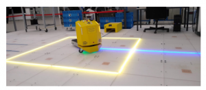
Figure 10: AGV and IF interact so that the yellow safety zone moves with the AGV. The IF detects an zone entry and can trigger the AGV to change direction or to stop.
3.5 Use Case ’BoxAGV’
Another application of the IF comes from the field of intralogistics and shows the use of the BoxAGV, which was adapted to the real production scenario described in [20]. The presented example relates to the production of interior parts, like headrests and side bolsters, for various vehicles. It is suitable, because the transition of a Manually Operated Intralogistics (MOL) to the new material supply concept of the In-plant Milkrun System (IMS) is already being discussed there. Furthermore, the paper includes a production layout and data on which the application example of the Novel BoxAGV System (NBS) can be based on. The comparison of the three material supply concepts does not claim to be complete and/or be generally valid. Further, it does not take into account the influencing factors that occur in practice, such as the robustness of the concepts with regard to the failure of critical components, fluctuations in demands or similar. The comparison rather serves as an indication for a possible operational capability of the NBS.
With the beginning of the 1990s, stationary storage capacities were gradually replaced by trucks moving in public roads. Responsible for this is the Just-In-Time (JIT) production concept [21, 22] which is widely used today. This relocation is not only to be criticized from an ecological point of view, but if the development is viewed from a business point of view, the JIT concept is extraordinarily successful: Warehousing and thus its capital tie-up can be significantly reduced. JIT can be scaled and transferred to the logistics of convertible production. This generates the following advantages:
- Liquidation of supermarkets (cf. central warehouse).
- Reduction of material handling (storage and retrieval).
- Minimum quantity of goods in the production process.
- Shorter throughput times and reduced capital tie-up.
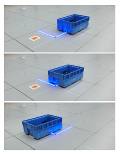
Figure 11: The three pictures show a time sequence in which the BoxAGV follows the dynamically controllable blue line to a WPT unit in order to get recharged.
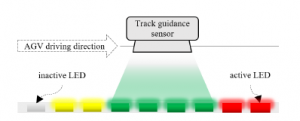
Figure 12: Based on the author’s patent [23] an easy to use optical guidance system for mobile robot applications in combination with the IF is proposed. Conventional guiding lines that are painted on the floor, can be replaced by dynamically controllable LED guiding lines.
The IF is suitable in particular for use in internal logistics. Resources (goods, machines and employees) can be organized dynamically with the help of the IF visualization function. This means that it is no longer necessary to depend on rigid production layouts, but can, for example, redefine and reroute goods flows depending on the order situation. If this dynamic route modification is taken as a base for an AGV’s track guidance, it is possible to react ad-hoc to unforeseen events in the production. Figure 12 shows that a single LED segment, for example consisting of eight single LEDs, is sufficient to realize track guidance. The segment not only sets the direction of the AGV, but also its speed. With only three colors the speed control can be built up:
- The BoxAGV remains at its current speed, while detecting a green light only.
- While detecting a yellow light, the BoxAGV controller will interpret this as an acceleration command.
- A red light decelerates the BoxAGV from its current speed to zero.
Today’s AGVs used in industrial environments are expensive since, as autonomous transport machines, they must have costintensive components like battery, on-board computer, localization system and safety devices. As a result, the investment costs for a fully automated logistics are also high. The use of the simply designed BoxAGV, which is centrally navigated and supplied by WPT systems, is a promising approach for the automated logistics of the convertible production. Due to the BoxAGVs slow driving speed of max. 1 km/h and its max. payload of 50kg, complexity and costs can be reduced. For example, costs can be saved using simple safety edges instead of laser scanners for mobile safety applications. Additional collision protection measures should also be considered. Here, the IF provides predictive safety through its built-in weight and object detection on the total production area. In order to illustrate the potential savings and technical possibilities of the NBS concept in comparison with the IMS solutions and the MOL, a real production scenario from the operational practice will be examined.
3.5.1 Production Layout
As shown in Figure 13, the predominantly manual production of car interior parts is divided into a logistics and a production sections with a total area of 1,350m2. One third of the available area is reserved exclusively for logistics applications and two third is available for production. A closer look at both sections reveal a further subdivision into manufacturing, storage, traffic, administration and infrastructure areas.
The division of areas is partly determined by the building’s structure itself (stairwells, escape routes), organizational requirements (offices, social rooms) and the type of manufacturing (workplaces, storage areas, logistics routes). The organizational and productionspecific areas can be partially or completely adapted by changes in the production technology. In the following, the areas specified by the construction are considered to be non-adaptable. Table 2 applies the area allocation to the manufacturing plant and determines the area that is required for manually operated production logistics. It is obvious that only one third of the total area can be used for valueadded assembly activities, two third of the area is occupied by traffic routes (marked by red lines) and storage areas. Therefore, [20] also highlights that one of the most urgent problems is the lack of space in production. Furthermore, the turnaround time of incoming and/or outgoing materials is criticized too. Materials sometimes lie on the racks for longer than one shift, which means that the logistics process is not optimally synchronized with the production process.
The production logistics process is considered and the three applicable logistics concepts (MOL, IMS and NBS) are compared with each other in terms of their capital and operational expenditure. The comparison is based on the data published in [20] and the available practical and calculated values for the IF and BoxAGV. It serves to identify the market and technology position of the novel logistics concept NBS compared to existing systems, but is not to be understood as an extensive and generally valid research study. This is part of subsequent studies that foresee an implementation of the NBS concept in a real manufacturing environment.
The production is run in two shifts, with one shift lasting eight hours. Of these, 7.5 hours are net working hours. The working and assembly stations are marked as gray areas in Figure 13. The material buffer in the workstations is divided into input (blue) and output (green) materials and has a capacity for two hours of production time. In the current scenario, logistics is provided in each shift by two qualified workers who travel between the supermarket and the workstations with pallet trucks and handcarts. The data basis [20] is accompanied by a component list of a center console as shown in Table 3. It includes the main components only. Small parts such as screws or washers are not listed. The bill of materials also contains information on the packaging unit (PU) of the components and determines their turnaround time based on the target production quantity of 296 pieces per shift.
Table 2: The layout of the manufacturing area is shown in Figure 13, where traffic routes, production and storage areas are the main uses of the total area.
| Type of area | Share | |
| Traffic | 463m2 | 34% |
| Manufacturing | 436m2 | 32% |
| – Area for the workers | 388m2 | 28% |
| – Workbenches/Machines | 48m2 | 4% |
| Storage | 363m2 | 27% |
| Administration | 74m2 | 6% |
| Infrastructure | 14m2 | 1% |
| Total | 1,350m2 | 100% |
Table 3: Bill of materials containing the main components of a center console including the numbers of components per PU, the consumption per shift and the coverage of one PU. The components are provided in a standard VDA box with a capacity of 0.072m3, type SLC 8280, 6280 and 6410. Original data taken from [20].
| Component | Quantity | Consumption | Coverage |
| 1 Support arm | 192 pcs./PU | 1.54 PU/shift | 292 min/PU |
| 2 Retainer | 180 pcs./PU | 1.64 PU/shift | 274 min/PU |
| 3 Storage | 24 pcs./PU | 12.33 PU/shift | 36 min/PU |
| 4 Handle | 1,250 pcs./PU | 0.24 PU/shift | 1,900 min/PU |
| 5 Foam part 1 | 60 pcs./PU | 4.93 PU/shift | 91 min/PU |
| 6 Foam part 2 | 16 pcs./PU | 18.50 PU/shift | 24 min/PU |
| 7 Cover lid 1 | 40 pcs./PU | 7.40 PU/shift | 61 min/PU |
| 8 Cover lid 2 | 54 pcs./PU | 5.48 PU/shift | 82 min/PU |
| 9 Cup holder 1 | 21 pcs./PU | 14.10 PU/shift | 32 min/PU |
| 10 Cup holder 2 | 432 pcs./PU | 0.69 PU/shift | 657 min/PU |
Since [20] has not synchronized the products assembly location with the layout and the paper does not provide any additional bill of materials, the author has made the following definitions to determine the benchmark figures:
- Similarly, assembly products are produced in the manufacturing, where the center console is taken as example to all assembly stations.

Figure 13: Layout of the logistics and production area for car interior parts, consisting of seven assembly zones, in which the blue rectangles represent goods entry areas, the green ones the goods exit and the grays the workstations. The walking and logistics routes are marked in red and their lengths are listed. The H–symbols indicate the routes of two milkruns described in [20].
- Ten consoles will be packed into one PU in order to form one outgoing box.
- Milkrun stops are defined according to Figure 13, where the start and end point of a milkrun is located at the supermarket.
With the help of Table’s 3 data and the assumptions made, the time-related box throughput in production can now be determined. The Figure 14 shows the time points and quantities of the incoming and outgoing boxes to be handled by the internal logistics over one station and shift. Based on the assumption that similarly complex products are also produced in the other six assembly stations, the handling process can be transferred to them as well. The process does not consider any disturbing effects in the production or logistics chain. It is therefore easy to see that a lack of synchronization between production and logistics, as well as disturbances acting on the logistic chain, can significantly increase the simultaneous material requirements, even though there are buffer at each station.
Furthermore, the number of box storage spaces and the total number of boxes in production can also be calculated from Table 3 and the assumptions made. For this purpose, an assembly station is divided into input, storage and output spaces. In the production start-up configuration, it is planned that all components are available in one box each and that there is also a buffer for each material to bridge a two-hour supply breakdown. The empties storage spaces at the assembly station are dimensioned accordingly. Table 4 shows that the throughput of boxes per shift is 94. This means that in average every five minutes, one box must be fed to or removed from the assembly station. In this case, a usage of the material buffer is not necessary. The buffer capacity is based on the requirement to guarantee a stand-alone manufacturing over two hours.
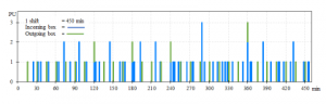
Figure 14: Throughput of input and output boxes at an assembly station over one shift. The incoming boxes with the ten main components of the center console are marked blue and the outgoing boxes with the finished product are marked green. In total 94 boxes are handled over per shift.
To dimension the storage capacity of an assembly station with components correctly, the autonomous production time of two hours is taken as a basis first. Table 3 shows for each component how much production time can be represented by a full box. This time per box is defined as the coverage. Dividing the buffer time of two hours by the coverage gives the number of boxes required. Since this result is usually not a natural number, the value is rounded up to full boxes. As there should always be a full box of each component at the workplace at the beginning of a shift, the result of the storage space calculation must be reduced by this box. The same number of full boxes in the material buffer must be matched by the number of empty box storage spaces. So, the assembly station has in total 21 storage spaces for empty boxes and 21+10 spaces for full boxes. In order to determine the minimum number of boxes in production, it is assumed that the number of boxes handled per shift as well as in the storage areas of the assembly stations must be provided. Applying this to the present production, a minimum number of 875 boxes is obtained. The following comparison of the three logistics concepts MOL, IMS and NBS bases on the figures of this subsection.
Table 4: Throughput and number of boxes of one assembly station, considering the start-up phase of production and the buffer for at least two hours continuous production.
| Start-up | Buffer for 2h production | ||
| Component | full boxes | full boxes storage space | Throughput |
Incoming boxes
| 1 Support arm | 1PU | 0PU | 0PU | 1 PU/shift |
| 2 Retainer | 1PU | 0PU | 0PU | 1 PU/shift |
| 3 Storage | 1PU | 3PU | 3PU | 12 PU/shift |
| 4 Handle | 1PU | 0PU | 0PU | 1 PU/shift |
| 5 Foam part 1 | 1PU | 1PU | 1PU | 4 PU/shift |
| 6 Foam part 2 | 1PU | 4PU | 4PU | 18 PU/shift |
| 7 Cover lid 1 | 1PU | 1PU | 1PU | 7 PU/shift |
| 8 Cover lid 2 | 1PU | 1PU | 1PU | 5 PU/shift |
| 9 Cup holder 1 | 1PU | 3PU | 3PU | 14 PU/shift |
| 10 Cup holder 2 | 1PU | 0PU | 0PU | 1 PU/shift |
| 10PU | 13PU | 13PU | 64 PU/shift |
Outgoing boxes
| A Center console | 0PU | 8PU | 8PU | 30 PU/shift |
3.5.2 Comparison of the Logistics Concepts
Manually Operated Logistics The MOL is characterized by using manual transport equipment and a low degree of digital information and processing systems. MOL is limited in its complexity and can easily be applied to low variant and continuously running productions. Since it is operated manually, high personnel expenditure is necessary to ensure the material supply – corresponding to the variety of parts, their throughput and the logistic routes length.
In-plant Milkrun System The IMS is an extension of MOL. Logistics employees are still in charge of driving tugger trains, loading and unloading boxes and checking the material quantities by visual inspection. In comparison to MOL, the operation of IMS requires more use of digital information and processing systems as well as the extension of organizational processes. For example, a production with IMS requires defined stops in the shop floor and a schedule with accurate arrival times. This requires a good synchronization of production and logistics that can be implemented with an appropriate production automation technology. In return, productivity gains and personnel cost savings are possible.
Novel BoxAGV System The NBS bases on the IF combinated with the BoxAGV. It represents a fully automated logistics concept. Each box can be controlled autonomously, without the investment cost disadvantage of today’s AGV solutions. In contrast to the logistics concepts MOL and IMS, no persons are required to perform the transport task. But the extensive use of networked information and processing systems is necessary or have to be implemented initially. In addition to the automation of the transport task and the associated reduction in personnel costs, the NBS offers a significant saving of space in production by transferring the material storage to the traffic routes. Due to the demand-driven material supply, NBS reduces the risk of production breakdowns and is therefore more robust than MOL and IMS.
Table 5: Investment and operating expenditures of the logistics concepts MOL, IMS and NBS in a quick comparison.
| Cost category | MOL | IMS | NAS | ||
| Building | 44,388EUR | 44,388EUR | 39,604EUR | ||
| – Space costs /month /m2 [24] | 2.74EUR | ||||
| – Total production area | 1.350m2 | 1.350m2 | 1.205m2 (1) | ||
| Logistics equipment | – are not considered – | ||||
| Transport equipment | 1,270EUR | 2,392EUR | 83,813EUR | ||
| – 4x Electric pallet truck [25] | 10,156EUR | ||||
| – 2x Platform truck [26] | 5,580EUR | ||||
| – 6x Trailer [27] | 3,558EUR | ||||
| – 351x IF panel acc. Figure 15 | 280,800EUR | ||||
| – 854x IF cover panel | 170,703EUR | ||||
| – 438x BoxAGV (2) | 219,000EUR | ||||
| Staff costs | 159,360EUR | 79,680EUR | 0EUR | ||
| – Workers per shift | 2 | 1 | 0 | ||
| Annual expenditures | 205,018EUR | 126,460EUR | 123,417EUR | ||
- Elimination of the supermarket and its traffic area → 145m2.
- Each BoxAGV can transport up to 2PU.
Since the current state of development of NBS and the data basis of the described production do not allow a detailed cost comparison, the Table 5 is intended to provide a rough cost evaluation of the three logistics concepts shown. It shall be proven that NBS is principally interesting from its capital and operational expenditures compared to MOL and IMS. The table bases on a general operating lifetime of the transport equipment of eight years [28]. This period was also applied for the IF, so that the investment sum in the individual logistics concepts is depreciated on a linear method over eight years. Furthermore, the annual income of a logistics employee is set at 33,200EUR for the comparison, to which an employer’s contribution of 20% to social insurances is added to determine the staff costs [29].
The logistics concepts are compared in three cost categories. For the purpose of completeness, immobile logistics equipment, such as racks, signage and similar equipment, is also listed. But this cost category is not used to evaluate the concepts. Typically, transport equipment is included in the investment costs and staff in the operating costs. The cost of the building may fit into one category or the other, depending on whether the company owns the building or not. If the building is rented, the costs of rent, electricity, water and heating should be allocated to the operating costs. When comparing the annual expenditure, it is remarkable that the lower the degree of automation and rationalization in the logistics concept, the higher the costs. In the MOL concept the personnel costs are dominant and represent the largest part with three quarters of the total costs. The NBS concept is particularly capital-intensive, but it is cheaper over the eight years of operation compared to MOL. NBS and IMS are roughly equal in price. In addition to investment and operating expenditure considerations, the logistics concepts can also be evaluated according to other criteria. For example, the examination of adaptability to changing market and production conditions is an interesting evaluation criterion that should be considered before deciding on a specific logistics concept. Due to the focus of this paper on the NBS introduction, comparing and delimiting studies are described in subsequent papers. Therefore, a preliminary qualitative list of NBS logistic concept advantages is given here:
- The IF can detect obstacles along the traffic routes with its load cells and redirects the flow of materials automatically by changing the displayed route of the BoxAGV.
- Batch tracking can be carried out by using the built-in LED stripes or an e-paper display unit. The visualization makes it easier to find required batches or to implement space-saving chaotic storage on the shop floor.
- Only a limited number of traffic routes in production are suitable for tugger trains. This limits the automation gain of the IMS concept. As shown in the layout Figure 13, tugger trains are used on the main routes, because curves are not large enough or necessary safety distances [30] cannot be guaranteed. Logistics employees are therefore still forced to carry out material transports manually.
- The MOL is basically flexible, but sensitive to disruptions due to the low degree of interconnection between production and logistics. Bottlenecks that arise here, affect the entire manufacturing process. Due to its high degree of interconnection, the NBS is more robust and less error prone.
- Compared to standard AGV solutions, the distances traveled by the BoxAGV are rather short, so that a BoxAGV can generally be built more simply and therefore more economically. Standard AGVs are designed for a daily mileage of 15…20km [31]. In contrast, the BoxAGV has to run an average travel distance of less than 200m (warehouse → assembly station → warehouse) in one shift.
4. Conclusion
In the factory of the future, the floor, walls and ceiling will be the only elements that are installed fixed. Production equipment is mobile and can be flexibly combined to form new production lines. Particularly the transport of goods is performed automatically and made more flexible in the sense of the convertible production. To ensure the competitiveness and future viability of a production company according to the customer demands, the convertible production is becoming more and more essential. Storage space inside the factory like supermarkets is reduced, since the material is in a continuous flow on the BoxAGV. Communication takes place in real-time and humans are the decision makers, supported by assistance systems that operate on an artificial intelligent core.
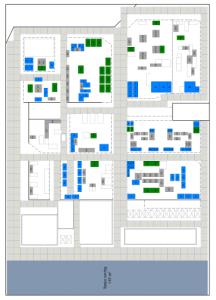
Figure 15: Implementation proposal of the IF into the described production, in which the traffic routes are equipped with standard panels. On this area, the basic functionality of the IF visualization, object detection and WPT for BoxAGV charging is provided. The floor in the area of the assembly stations is built up with regular cover panels.
The IF supports convertibility best and is suitable as an universal and open infrastructure platform for the FOF. Using the IF in such an industrial environment, opens a wide range of applications and makes our current manufacturing processes faster, more flexible and more transparent. A contribution to the convertibility is made by the NBS concept, which prospectively offers cost and space advantages over current logistics solutions. It reduces the material stock at the assembly stations by providing a demand-driven supply. Supermarkets can be downsized by chaotic warehousing or eliminated at all by shifting logistics to the traffic routes. This enables rapid changes in company intralogistics and thus a quick response to market-relevant developments. The close integration of production and logistics also makes manufacturing processes faster and more efficient than today. It is not necessary to search for specific batches (boxes) because each BoxAGV can navigate to a defined point on command or the IF can show the user the way to the BoxAGV via its LED system. The BoxAGV can be used to save on personnel costs or to assign logistics staff to higher-value tasks too.
Overall, the combination of IF and BoxAGV seems to be promising for production companies, especially for companies with a high level of manual and multi-variant assembly. For this reason, a further development of the BoxAGV and the IF is planned. It includes the WPT of transportation and production equipment not only at specific spots, but also along a track and in an open area as described in [15].
- German Association of the Automotive Industry (VDA), “Small Load Carrier (SLC) System,” Technical Report VDA 4500-1.
- H. Ku¨hnle, “Paradigmenwechsel im Produktionsbetrieb – Die Fraktale Fabrik,” in H.-J. Warnecke, H.-J. Bullinger, editors, Produktionsstrategie fu¨ r das 21. Jahrhundert, 9–43, Springer Berlin Heidelberg, Berlin, Heidelberg, 1994.
- E. Westka¨mper, “Marktorientiertes Produzieren in dynamischen Strukturen,” in H.-J. Warnecke, editor, Fabrikstrukturen im Zeitalter des Wandels – Welcher Weg fu¨hrt zum Erfolg?, 9–22, Springer Berlin Heidelberg, Berlin, Heidelberg, 1995.
- E. Westka¨mper, “Produktion in Netzwerken,” in G. Schuh, H.-P. Wien- dahl, editors, Komplexita¨t und Agilita¨t – Steckt die Produktion in der Sack- gasse?, 275–291, Springer Berlin Heidelberg, Berlin, Heidelberg, 1997, doi: 10.1007/978-3-642-60841-4 19.
- E. Westka¨mper, Technical report, Institut fu¨r Industrielle Fertigung und Fabrik- betrieb (IFF), Stuttgart, Stuttgart, 2006.
- W. Gu¨ nthner, K. Furmans, K.-H. Wehking, K.-P. Rahn, M. Ten Hompel, In- tralogistik im Dialog mit Forschung und Lehre, 239–276, Springer Berlin Heidelberg, Berlin, Heidelberg, 2006, doi:10.1007/978-3-540-29658-4 6.
- M. Hofmann, D. Korte, Neuartiges Logistikkonzept fu¨ r die automobile End- montage ohne Band und Takt, 85–100, Springer Berlin Heidelberg, Berlin, Heidelberg, 2020, doi:10.1007/978-3-662-60491-5 8.
- M. Mandat, “Produktportfolios der fu¨ nf großen deutschen Autohersteller in Deutschland: 1990 bis 2014: Das Dilemma mit der Vielfalt,” .
- Volkswagen, “Absatz des VW Golf im Zeitraum der Jahre 1974 bis 2012 nach Modell,” 2012.
- H. Meier, N. Hanenkamp, Komplexita¨tsmanagement im Lebenszyklus individ- ualisierter Produkte im Maschinen- und Anlagenbau, 623–639, Gabler Verlag, Wiesbaden, 2005, doi:10.1007/978-3-663-01577-2 38.
- T. Stehle, U. Heisel, Konfiguration und Rekonfiguration von Produktionssys- temen, 333–367, Springer Berlin Heidelberg, Berlin, Heidelberg, 2017, doi: 10.1007/978-3-662-55426-5 39.
- J. Stratmann, “Blick unter die VW Golf 7 Karosserie: U¨ ber die Nervenbahnen der modernen Automobile,”.
- Komax, “Zeta 640/650, [Online]. Avail- able: https: // www.komaxgroup.com/en/ Products-and-Solutions / Products / Harness-Manufacturing / Zeta-640-650/” .
- J. Stillig, N. Parspour, “Advanced Manufacturing based on the Intelligent Floor,” in 20th IEEE Mediterranean Electrotechnical Conference (MELECON), 248– 253, 2020, doi:10.1109/MELECON48756.2020.9140660.
- J. Stillig, N. Parspour, “Novel Concept for Wireless Power Transfer Modules,” in 2020 International Conference on Broadband Communication, Wireless Sensors and Powering (BCWSP), 167–172, 2020, doi:10.1109/BCWSP50066. 2020.9249465.
- T. Kuhlmann, P. Spanier, M. Ehlich, Potenziale einer industriellen Gleich- stromversorgung, 9–35, Carl Hanser Verlag GmbH & Co. KG, Mu¨nchen, 1997, doi:10.3139/9783446466128.002.
- F. Regnery. [Online]. Available: https: // www.vde.com / resource / blob / 1888372 / 2fab7ab57295bebd7fbd3769314e9efa / faktencheck-bidirektionale- energiefluesse—download-data.pdf
- J. Kesselring, Prozessbegleitende Planung und Konfiguration von Fo¨rdertech- nikanlagen unter Zuhilfenahme von virtuellen Konfigurationsmustern und Kon- figurationsmodellen, Ph.D. thesis, Karlsruher Institut fu¨ r Technologie (KIT), 2017, doi:10.5445/IR/1000075521.
- “Flurfo¨rderfahrzeuge – Sicherheitstechnische Anforderungen und Verifizierung, Teil 4: Fahrerlose Flurfo¨rderfahrzeuge und ihre Systeme,” 2020.
- M. Knez, B. Gajsek, “Implementation of In-plant Milkrun System for Mate- rial Supply in Lean Automotive Parts Manufacturing,” in 12th International Conference on Logistics and Sustainable Transport 2015 (ICLST), 121–126, 2015.
- M. Ellrich, “Vor- und Nachteile des Produktions- und Logistiksystems,” Ge- ographie Infothek, 2.
- L. Ickert, U. Matthes, S. Rommerskirchen, E. Weyand, M. Schlesinger, J. Lim- bers, Technical report, Bundesministerium fu¨r Verkehr und digitale Infrastruk- tur, Basel/Berlin, 2007.
- J. Stillig, “Verfahren zum Betrieb eines Spurfu¨hrungssystems,” 2019.
- Haufe Online Redaktion, “Logistik: Nebenkosten fu¨r Lager und Cross Docks leicht gestiegen,” .
- STILL GmbH, n.d. [Online]. Available: https: // www.still.shop / ecu-15-c.html
- STILL GmbH, n.d. [Online]. Available: https: // www.still.shop / ltx-20.html
- Carl Beutlhauser Kommunal- und Fo¨rdertechnik GmbH & Co. KG, “Routenzug Katalog,” Booklet.
- Bundesministerium der Finanzen [Online]. Available: https: // www.bundesfinanzministerium.de / Content / DE / Standardartikel / Themen / Steuern / Weitere Steuerthemen / Betriebspruefung / AfA-Tabellen / Ergaenzende-AfA-Tabellen / AfA-Tabelle AV.html.
- StepStone Deutschland GmbH, “Welches Gehalt verdient man im Bereich Logistik-Mitarbeiter/in?” n.d.
- DGUV Fachbereich Handel und Logistik, “Routenzu¨ge – Einsatz von Schlep- pern und Anha¨ngern als Routenzu¨ge,” Technical Report FBHL-008, 2018.
- Dahl Automation GmbH, n.d. [Online]. Available: https: // www.mobile- robots.de / 70 / robotize