
Sensorless Control and Corrected Error Commutation of the Brushless DC Motor
Volume 6, Issue 1, Page No 224-229, 2021
Author’s Name: Anatoly Stepanova), Vitaly Enin
View Affiliations
Department of Electrical and Industrial Electronics, Bauman Moscow State Technical University, Moscow, 105005, Russia
a)Author to whom correspondence should be addressed. E-mail: stepanov.bmstu@gmail.com
Adv. Sci. Technol. Eng. Syst. J. 6(1), 224-229 (2021); ![]() DOI: 10.25046/aj060125
DOI: 10.25046/aj060125
Keywords: Sensorless control, Error commutation, Brushless DC motor, Simulation

Export Citations
This paper presents a simple method for correcting the error of commutation windings for sensorless control of a brushless DC motor with a small inductance. Switching error analysis is performed based on the phase currents of the switched-off and switched-on phases. To correct the commutatiuon signals for the inverter, a speed-independent function is used, calculated from the back-EMF, by selecting its coefficients. The back-EMF is calculated for the system obtained by transformed a three-phase system to a two-phase one, which reduces the system dimension. An algorithm for start-up the motor with sensorless control based on the method of align and damping the rotor vibrations in a stable equilibrium position is proposed. The back-EMF is approximated by a function based on a piecewise linear function and an inscribed ellipse, for a more accurate description of the shape of the back-EMF. This approximation is used when simulation the motor. The simulation confirms the effectiveness of the proposed method for correcting the commutation error in the case of sensorless control of a low-power BLDC motor.
Received: 30 August 2020, Accepted: 29 December 2020, Published Online: 15 January 2021
1.Introduction
This paper is an extension of conference report “Sensorless control of low-power brushless DC motor based on the use of back-EMF,” presented in “2019 International Ural Conference on Electrical Power Engineering (UralCon 2019)” [1].
In the extended version of the paper, in comparison with the conference paper, a method for correcting error of commutation winding and the start-up procedure based on the alignment of the rotor position in the stable equilibrium position of brushless DC motor is proposed, which makes it possible to improve the reliability and quality of sensorless control.
The rectifier of the electrical motors, in particular the brushless DC motors (BLDC) are widely used in automation and control systems, as well as in orientation and navigation systems as a gyroscope drive [2 – 4]. Usually, the power of the BLDC windings is produced by a semiconductor inverter, whose transistors are switched by signals from sensors installed on the motor stator.
The use of rotor position sensors has disadvantages associated with an increase in the price of the electric drive, the accuracy of their installation, which leads to errors in determining the switching moments of the windings, unreliability of the sensors in difficult environmental conditions. To eliminate these shortcomings, the methods of sensorless control of the BLDC motor have been developed.
In case of sensorless control, commutation signals are generated using back-EMF or flow, calculated from phase currents and voltages. The most widely used methods are those using back-EMF.
The most widely used methods of sensorless control based on the analysis of back-EMF are considered in [5-11]. If the neutral point of the motor is not available, the terminal voltage determines the moment when the back-EMF of the disconnected phase passes through zero (zero crossing point). Switching must be performed with a delay of 30 electrical degrees, after passing the back-EMF through zero. In [5], the least squares method is used to refine the switching points, but this does not guarantee accurate determination of the switching points, since the terminal voltage contains noise and pulses generated by the inverter. The implementation of these methods requires additional phase-shifting circuits, including a timer. The non-ideality of the back-EMF, the delay created by the low-frequency filter significantly reduces the reliability of these methods.
In [12, 13], a velocity-independent G-function calculated from the back-EMF is used to determine the commutation points. Commutation points are determined when the absolute value of this function exceeds a certain threshold value. The back-EMF contains noise and pulses generated by the inverter, which can lead to erroneous determination of commutation points. The disadvantage of this method is also the ambiguity of choosing a threshold value.
To determine the commutation points in [14, 15], the third harmonic is used. This method requires creating a virtual third point. To form a neutral point, an additional electrical circuit is required, which is a disadvantage of this approach.
One of the problems with sensorless control is the problem of starting the motor and its operation at a low speed of rotation, in this case, the back-EMF of rotation is zero or very small. Then, determining the position of the rotor by the back-EMF of rotation is difficult or almost impossible.
In [16], when starting, the position of the rotor is initially set by the reaction of the current at magnetic saturation if the axis of the flow created by the current and the magnetic axis coincide. Only one current sensor is used. Then, after starting, the rotor is accelerated to the speed at which it is possible to switch to sensorless control of the winding switching. When the rotor position is aligned, oscilations occur in the vicinity of the equilibrium position, which reduces the reliability of this method.
Despite the large number of works on sensorless control, the problem of reliability and accuracy of determining the commutation points for the BLDC motor are relevant and require further research.
2. Mathematical model of brushless DC electric motor
Here we describe a mathematical model of a three-section electric BLDC motor. The power supply circuit of the windings of a three-section, brushless DC motor by an electronic commutator on field-effect transistors is given in Figure 1
The equations in the phase coordinates for the sections of BLDC motor with permanent magnets taking into account the mutual inductances of the sections have the form (the case of an implicit pole rotor is considered):
 where Rs – active resistance of section stator winding; ia, ib, ic – currents in the windings of the stator sections; Ls – inductance winding sections; Ms – mutual inductance of the windings of the sections; ea, eb, ec – back-EMF of the stator windings; ua, ub, uc – voltage applied to the windings of sections; un – neutral point voltage. In wye connection ia + ib + ic =0.
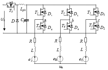 Figure 1: Three-section BDCM winding power supply circuit
Let us define the inductance of the stator along the longitudinal and transverse axes Ld = Lq and the inductance L0 for the zero sequence. The phase inductances of the windings of the sections in the rotating coordinate system d, q are defined as follows: Ls = (L0 + 2Ld)/3; Ms =(Ld – L0)/3.
Using the transformation (a particular form of the transformation matrix E. Clarke)
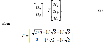 For the transformation matrix T, the following equality holds: T-1 = Tt (Tt is the transposed matrix), T T-1 = E, E – unit matrix.
Transform (2) a three-phase system (1) to a two-phase system
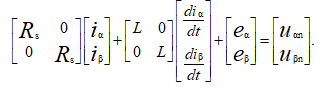 where L = Ls + Ms.
Using the transformation (2) we will express the back-EMF in the system α, β
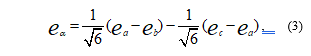
 The back-EMF differences eab = ea – eb, ebc = eb – ec, eca = ec – ea. They are calculated using equation (1). to calculate the back-EMF according to (3),(4), it is not necessary to determine the voltage at the neutral point.
Back-EMF sections at a constant rotational speed vary according to the law ea(θ) = keωeΦ’a(θ), eb(θ) = keωeΦ’b(θ) , ec(θ) = keωeΦ’cθ), where ωe = pω, (ω – is the angle rotor speed, p – number of pairs of poles.
Trapezoidal function dΦ/dθ (Φ is magnetic flux, θ electric angle) is approximated by piecewise linear function with inscribed ellipse [1]. This function Φ'(θ) is used when simulation the BLDC motor.
Graphs of the functions Φ’a(θ), Φ’b(θ), Φ’cθ) for a three-phase and functions Φ’αθ), Φ’βθ) for a two-phase system are shown in Figure 2, 3.
 Figure 2: Trapezoidal functions Φ’a(θ), Φ’b(θ), Φ’cθ)
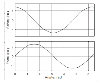 Figure 3: Functions Φ’αθ), Φ’βθ) in system α, β
3. Algorithm sensorless control BLDC motor in system α, β
The most widespread in practice is 120 degree commutation, in which the winding is connected to the source at an interval of 120⁰ electric degrees, then disconnected from the source at an interval of 60⁰ electric degrees.
For 120-degree commutation, the angles of switching on and off phases , the function value is selected, which determines the value of the back-EMF of the sections at the time of switching. The dependence of the back–EMF phase in relative units expressed using the function Φ'(θ) is shown in Figure 3, from where it follows for 120 degree commutation Φ'(60˚) = Φ'(300˚), Φ'(120˚) = Φ'(240˚).
To determine the commutation points, the values of the back-EMF in system α, β calculated by the formula (3), (4) are used. The ratio of the back-EMF eα(t), eβ(t) is equal to the ratio Φ’a(t), Φ’b(t) and does not depend on the speed of rotation of the rotor. The values of the functions Φ’α(θ), Φ’β(θ) for commutation angles are shown in table 1.
Table 1: The value of the function Φαʹ(θ), Φβʹ(θ) at the points of commutation
| θc | Φ’α(θc) | Φ’β(θc) | Φ’α(θc)/Φ’β(θc) |
| π/3 | C1(1+Φ’b) | C2(1+Φ’b) | 1/ |
| 2π/3 | -C1(1+Φ’b) | C2(1+Φ’b) | –1/ |
| π | -2C1(1+Φ’b) | 0 | –∞ |
| 4π/3 | -C1(1+Φ’b) | -C2(1+Φ’b) | 1/ |
| 5π/3 | C1(1+Φ’b) | -C2(1+Φ’b) | –1/ |
| 2π | 2C1(1+Φ’b) | 0 | ∞ |
In table С1 = , С2 = .
Let’s introduce the functions H1(t), H2(t),
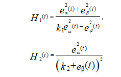 Coefficients k1 and k2 in accordance with table 1 should be equal to k1=3 and k2 =0. The function H1(t), H2(t) generates pulses at switching angles of 60, 120, 240, 300 electric degrees, and the function H2(t) at angles of 180 and 360 degrees. To determine points of commutation is set to the threshold value Ht. When the threshold value is exceeded (|H1(t)|> Ht or |H2(t)|> Ht), the functions H1(t), H2(t) determine the commutation. The calculated back-EMF for voltage and current windings contains pulses generated by the inverter, which are smoothed by a low-frequency filter. As a result of this, a error commutation occurs. The accuracy of determining the points of commutation is also affected by the threshold value. The error of commutation can be corrected by changing the coefficients k1, k2. For example, for angle of commutation =240 degrees, an increase in k1 (greater than 3) leads to a delay in the formation of the commutation signal, and when reducing k1, the commutation signal is produced ahead of time. The estimation of the error of commutation is made by comparing the current at the time of switching off the section ioff (tc) and the current at the time of switching on the section ion(tc +Δt) (tc – commutation of time, Δt – delay that takes into account the time of the transient process in the winding). The coefficients k1 and k2 are adjusted for the difference of these currents di = ioff(tc) – ion(tc +Δt).
When correcting the error commutation, the coefficient vectors K1 = [k11, k12, k13, k14, k15, k16], K2 = [k21, k22, k23, k24, k25, k26] whose initial values are set K1 = [3, 3, 3, 3, 3, 3], K2 = [0, 0, 0, 0, 0, 0]. Each element of the vector corresponds to a point of commutation 0˚, 60˚, 120˚, 180˚, 240˚, 300˚. Parameters are also set Δt, di. After determining the time of commutation, the value di is determined and the corresponding coefficient is adjusted based on the table 2. The values of the coefficients restricted to values. After several cycles of switching the windings, the error is reduced.
Table 2. The calculation of the coefficients k1, k2 of the error commutation corrected
| θc | di>0, ǀdiǀ>Δi | di<0, ǀdiǀ>Δi |
| π/3 | k1=k1–Δk, k2=0 | k1=k1+Δk, k2=0 |
| 2π/3 | k1=k1–Δk, k2=0 | k1=k1+Δk, k2=0 |
| π | k1=3, k2= k2–Δk 0 | k1=3, k2= k2+Δk 0 |
| 4π/3 | k1=k1+Δk, k2=0 | k1=k1–Δk, k2=0 |
| 5π/3 | k1=k1+Δk, k2=0 | k1=k1–Δk, k2=0 |
| 2π | k1=3, k2= k2 +Δk 0 | k1=3, k2= k2–Δk 0 |
For the model checking method was carried out for the model of the ideal typical signals eα(t), eβ(t), ia, ib, ic . The results of the computational experiment are illustrated in Figure 4 for the angle of commutation 240 electrical degrees. The error of commutationon each cycle is reduced almost to zero.
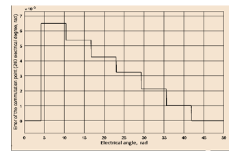 Figure 4: Error of commutation
The functional diagram of sensorless control and error of commutation correction is shown in Figure 5.
The procedure for starting the BLDC motor includes two stages: the first process of aligning the rotor in the equilibrium position, the second of accelerating up the rotor from the stable equilibrium position to the speed at which it is possible to transit to sensorless control of switching the motor windings. When the rotor is started, the rotor of BLDC is stationary or rotates at a very low speed. It is almost impossible to estimate the position of the rotor by the back-EMF of rotation, which in this case is zero or small. When switching two of the phase, the position rotor of which is unknown, acquires acceleration and moves to a stable equilibrium position. With a small damping, oscilations occur in the vicinity of a stable equilibrium position. When moving in the direction of a stable equilibrium position, the rotor accelerates, and when moving from the equilibrium position, it is slowed down. If the damping is low, the kinetic energy acquired during rotor acceleration is approximately equal to the potential energy accumulated during braking. When the rotor speed is zero and the rotor starts moving in the direction to a stable equilibrium position. The acceleration square is approximately equal to the braking square.
| Brushless DC Motor |
|
Calculation eα(t),eβ(t)
|
| Calculation H1(t), H2(t) |
|
Calculation k1(t),k2(t) |
| Formed signal for invertor |
|
Low-pass filter
|
| Invertor |
|
Calculation ea(t),eb(t),ec(t) |
| ia,ib,,ic |
| ua,ub,uc |
 Figure 5: The functional diagram of sensor-free control BLDC motor
Stable rotor equilibrium positions is depended on various load. The area of acceleration and braking depends on the magnitude of the voltage applied to the phases. Vibration damping when the rotor position is aligned is performed by reducing the acceleration square, which is performed by reduce of the voltage on the switching phases u = Ur. After passing a stable equilibrium position, the voltage on the phases increases u = Us, which reduces the angle deviation from the equilibrium position. When the speed becomes zero, the voltage reduces u = Ur (u – voltage of commutation phases). The acceleration square is reduced. The procedure is then repeated until the rotor position is aligned with the equilibrium position.
Let Sa(Δθ) be the acceleration area, and Sb(Δθ) be the deceleration area. For low damping, it must be performed Sa(Δθ) ≈ Sb(Δθ), Δθ = θ – θs.
Δθ(k+1) = (Sa)-1[Sb(Δθ(k)],
If the maping will be compressive if |Δθ(k+1)| < | Δθ(k)|, then the iterative process converges and Δθ tends to zero. The rotor position is aligned relative to the stable equilibrium position.
The moments of changing the voltage on the section are determined by changing the current of the section. After switching the winding, the current at the rotor acceleration initially decreases, and then increases when passing the equilibrium position is equal to the initial one. At this point, the voltage increases u = Us and a new value of the initial current is set. The current during braking first increases, and then decreases and reaches the initial value, at which point the voltage decreases u = Ur. The process is then repeated until the rotor position is aligned (Figure 6).
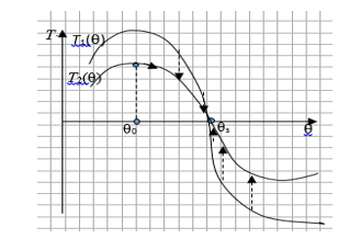 Figure 6: Aligned position of rotor
4. Simulation results
To substantiate and study the effectiveness of the proposed sensorless control, start-up and corrected error of commutation method for a low-power brushless DC electric motor with permanent magnet was simulated.
The simulation was performed using the MATLAB&Simulink system and models of a three-phase brushless DC motor and a power semiconductor bridge commutator of the SimPowerSystems expansion. A motor is an electric machine with a three-section winding on the stator and a multi-pole rotor with permanent magnets. BLDC motor parameters are given:
Rated DC Voltage – 27 V;
Rated speed, n = 2000 r/min;
Number of poles, p = 4;
Phase resistance, R = 6 Ω;
Phase Inductance, L = 0.42 mH.
When starting the motor, the position of the rotor is not determined. If one connects two sections of the motor to a DC voltage source, the rotor begins to move to a stable equilibrium position (stable point). Let ua = U0, uc = 0, phase “b” is disconnected from the source.
The proposed start-up procedure involves two steps for the transition to the sensorless control of BLDC motors. In the first step, the procedure is performed to align the rotor position and to calm down oscillation in a stable equilibrium position. At this step, a constant voltage of various values Ur = 27 V, Us =50 V was applied to the switching phases (phases a, c), which provided alignment of the rotor position and damping of vibrations around a stable equilibrium position. In the second step, a constant voltage was applied to the switching phases (phases b, c). After the speed set, there was a transition to sensorless control of commutation of the BLDC motor windings. Simulation of start-up and control of commutation of the BLDC motor windings was performed using the MATLAB/Simulink system. For Figure 7 the simulation results are presented: the function H(t). Function H(t) is sum H1(t), H2(t). The results of modeling the motor start and transition to sensorless control are shown in Figure 8.
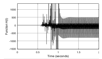 Figure 7: Function H(t)
 Figure 8: Start-up fnd transition to the sensorless control
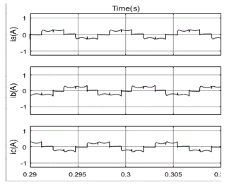 Figure 9: Corrected of phase current
To demonstrate the capabilities of the proposed method for correcting the commutation error, a simulation of BLDC motor with different speeds was performed. Error correction was performed by analyzing phase currents. Phase currents after error compensation are shown in Figure 9.
The table 3 shows the dynamics of the commutation error when it is compensated by the proposed method. At low speed=500 the initial commutation error was small. Initial commutation error was reduced to an error 0.12 electrically degree. At the speed of 1000, the initial error 3.5 electrically degree was also reduced by the correction method to 0.1 electrically degrees. At the nominal speed of rotation, the significant error of 14 elecctrically degree was reduced to 0.2 electrically degrees. These results confirm the possibility of reducing the compensation error in a simple corrected method.
Table 3: Error of commutation
| t, s |
Δθ, deg (n=500 r/min) |
Δθ, deg (n=1000 r/min) |
Δθ, deg (n=2000 r/min) |
| 0.01 | 1.25 | 3.5 | 13.9 |
| 0.05 | 0.96 | 1.9 | 10.8 |
| 0.1 | 0.81 | 1.6 | 5.2 |
| 0.15 | 0.54 | 1.35 | 3.7 |
| 0.2 | 0.56 | 1.08 | 2.1 |
| 0.25 | 0.45 | 0.54 | 1.6 |
| 0.3 | 0.12 | 0.1 | 0.2 |
5. Conclusion
The paper offers a simple method for correcting the commutation error in the case of sensorless control of a BLDC motor. A start-up procedure based on align the rotor position and damping its oscilations in a stable equilibrium position is proposed. This allows to accelerate the rotor and transient to sensorless control. The proposed method can increase the efficiency of sensorless control methods for BLDC motor with small inductive.
Conflict of Interest
The authors declare no conflict of interest.
- A.V. Stepanov, V.N. Enin, “Sensorless control of low-power brushless DC motor based on the use of back-EMF,” in 2019. IEEE Internatiol Ural Conference on Electrical Power Engineering (Uralcon), 277-283, 2019, doi:10.1109/URALCON.2019.8877642
- A.K. Arakelyan, A.A. Afanas’ev, The rectifier of the electric machine in the systems of electric drive,” M.: Higher school, 2006.
- A.P. Belkovsky, “Precision electric drive with valve engines,” – Moscow: MPEI, 2010.
- M. Bychkov and A. Krasovsky, “Taking Into Account Nonlinear Properties of Switched Reluctance Machines in Electric Drive Control Algorithms,” in 2018 X International Conference on Electrical Power Drive Systems (ICEPDS), Novocherkassk, 1-5, 2018, doi:10.1109/IWED.2018.8571868
- R. C. Guo, Z. Mu , J. D. Li, “Research on Position Sensorless Control System of High-Speed Brushless DC Motor,” in 2017 9th International Conference on Intelligent Human-Machine Systems and Cybernetics, 62-65, 2017, doi:10.1109/IHMSC.2017.21
- A. Halvaei Niasar, A. Vahedi, H. Moghbelli, “A novel position sensorless control of a four-switcy, brushless DC motor drive without phase shifter,” IEEE Trans. Power Electron., 23(6), 3079-3087, 2008, doi:10.1109/TPEL.2008.2002084
- H. Li, S. Zheng, H. Ren, “Self-Correction of Commutation Point for High-Speed Sensorless BLDC Motor With Low Inductace and Nonideal Back EMF,” IEEE Transactions on Power Electronics, 32(1), 642-651, 2017, doi:10.1109/TPEL.2016.2524632
- W.Li, J. Fang, H. Li, J. Tang, “Position sensorless control without phase shifter for high-speed BLDC motor with low inductance and nonideal back EMF,” IEEE Trans. Power Elecnron., 31(2), 1354-1366, 2016, doi:10.1109/TPEL.2015.2413593
- J.S. Park, K.L. Lee, S.G. Lee, W.H. Kim, “Unbalanced ZCP compensation method for position sensorless BLDC motor,” IEEE Trans. Power Electronics, 34(4), 3020-3024, 2019, doi:10.1109/TPEL.2008.2002084
- X. Zhou, X. Chen, F. Zeng, J. Tang, “Fast commutation instant shift correction method for sensorless BLDC motor based on terminal voltage information,” IEEE Trans. Power Electronics, 32(12), 9460-9472, 2017, doi:10.1109/TPEL.2017.2661745
- G. Su, J. McKeever, “Low-cost sensorless control of brushless DC motor using a frenquency-independent phase shifter,” IEEE Transaction on Power Electronics, 19(2), 296-302, 2004, doi:10.1109/TPEL.2003.823174
- S. Chen, X. Zxou, G. Bai, K. Wang, L. Zhu, “Adaptive commutation error compensation strategy based on a flux linkage function for sensorless brushless DC motor drives in a wide speed range,” IEEE Trans. on Power Electron., 33(5), 3752 -3764, 2018, doi:10.1109/TPEL.2017.2765355
- S. Chen, G. Liu, L. Zhu, “Sensorless Control Strategy of a 315 kW High-Speed BLDC Motor Based on a Speed-Independent Flux Linkage Function”. IEEE Trans. Ind. Electronics, 64(11), 8607-8617, 2017, doi:10.1109/TIE.2017.2698373
- G. Liu, C. Cui, K. Wang, B. Han, S. Zheng, “Sensorless control for hign-speed brushless DC motor based on the line-to-line back EMF,” IEEE Trans. Power Electron., 31(7), 4669-4683, 2016, doi:10.1109/TPEL.2014.2328655
- X. Song, B. Han, J. Fang, “High-precision sensorless drive for high-speed BLDC motors based on the virtual third harmonic back-EMF,” IEEE trans Power electron., 33(2), 1528-1540, 2018, doi:10.1109/TPEL.2017.2688478
- W. J. Lee, S.-K .Sul, “A New Starting Method of BLDC Motors Without Position Sensor,” IEEE Trans. Ind. Appl., 42(6), 1532-1538, 2006, doi:10.1109/TIA.2006.882668