Autonomous Robot Path Construction Prototype Using Wireless Sensor Networks
 , Vasco Nuno da Gama de Jesus Soares 2, João Alfredo Fazendeiro Fernandes Dias 3
Adv. Sci. Technol. Eng. Syst. J. 6(1), 169–177 (2021);
 DOI: 10.25046/aj060119
The use of wireless sensor networks (WSN) can be a valuable contribution in disaster situations or life-threatening exploration. Using wireless mobile robots, it is possible to explore vast areas without human intervention. However, the wireless network coverage that can keep mobile robots connected to the base station / gateway is a major limitation. With this in mind it was created a prototype of an extensible WSN using mobile robot nodes that cooperate amongst themselves. The strategy adopted in this project proposes using three types of nodes: master node, static node, and robot node. Three different algorithms were also developed and proposed: Received Signal Strength Indication (RSSI) Request; Automovement; Robot Cooperation and Response to Static Node. The performance evaluation of the prototype was carried out using a real-world testbed with each developed algorithm. The results achieved were very promising to continue the evolution of the prototype.
1.Introduction
This paper is an extension of work originally presented in conference 2020 15th Iberian Conference on Information Systems and Technologies (CISTI 2020) [1].
Wireless Sensor Networks (WSNs) are composed by small nodes spread in an area of interest to measure environmental conditions such as temperature, sound, humidity, although they have many other uses [2]. Each node can be seen as a small computer, having processing, sensing and communication capabilities. The nodes connect to each other wirelessly and can cooperate in collecting information and routing it to an end user [3].
The need for extensible WSNs is tied with monitoring situations that require the deployment of a WSN. Situations such as forest fires or fires is large buildings [4], determining the extent of damage of earthquakes [5], nuclear disasters as in Fukushima, Japan, rescue operations, exploratory operations, mapping flooded caves, battlefield reconnaissance or planetary exploration [6]. In some of these situations it is possible for a human operator to deploy the nodes of the WSN. But in disaster situations, or any situation where human life could be endangered, it is necessary to use alternative methods of deployment, such as the use of mobile robots.
With this purpose in mind a testbed was used, which serves as a prototype for a WSN. The testbed used was composed of three different types of nodes: master, robot and static nodes. The master node is used so an end user can receive information from the network and send commands to any node. The static nodes serve as intermediate relays that connect the master node and the robot nodes. The robot nodes serve to extend the network, having mobility besides communication capabilities. The objective of this project is to create an extensible wireless network, using intermediate static nodes that connect a gateway to a moving robot node.
This document is organized as follows. Section I introduces WSNs and the goal of the project, Section II gives a review of related literature, with examples of similarly deployed WSNs. Section III describes the testbed and the libraries used for programming the nodes. Section IV describes the algorithms developed. Section V describes four scenarios used to evaluate the performance of the testbed with the described algorithms and the results achieved. Section VI discusses these results and Section VII concludes the report and proposes future avenues of exploration.
2. Related Work
There has been prior work on the problem of “as-you-go” or impromptu deployment of a WSN. In [4] and [7] are proposed algorithms for “as-you-go” deployment, in which an agent, human or robot, measures link quality at equally spaced intervals and makes placement decisions, while only moving forward along a line.
Some works consider a purely autonomous deployment of a WSN by mobile robots. In [6] is explored autonomous deployment of a WSN with the goal of human detection, in case of disaster situations, in which mobile robots perform simultaneous localization and mapping. In [5] mobile robots carry sensor nodes and measure the RSSI, to know when to deploy sensor nodes to ensure communication or restore the network.
Many of the proposed systems measure link quality, using communication metrics like RSSI or Packet Reception Ratio, and decide when to deploy a new relay when the metric satisfies predefined rules. In [8] such a system is used for dynamic deployment of a WSN through a breadcrumb system for firefighters. A breadcrumb dispenser is worn by firefighters and a link estimator uses the previous mentioned metrics to decide when to deploy breadcrumbs.
Works such as [9] also make use of mobile robots to deploy a WSN but focus on how these robots can help with problems such as coverage holes or collection of redundant sensors. They achieve this by using permanent grid-based deployment, with cluster concepts to reduce packets used in creating and maintaining the grid structure. Furthermore, they consider the communication range to be at least twice of the sensing range.
Cooperation between multiple agents is seen as an important problem to be explored. In [4] and [7] it is pointed the need for algorithms where two or more robots cooperate to deploy a WSN. While [6] calls for field test using two mobile robots and to address the communication issues that arise from coordination between multiple robots. These and more issues of multi-robot systems, such as reduction in network traffic, routing approaches and sensor data processing are pointed as areas that need appropriate operational methods by [5]. The study of communication metrics, such as RSSI, in various environments, to allow setting different parameters that could optimize the system, is called for by [8].
In the present study the aim is to use the communication metric of RSSI to know when a new node should be deployed and integrate this metric with cooperation between two mobile robot nodes. The RSSI metric has been used in studies such [10], [11] and [12] to locate the robot nodes, triangulating the robot node and static nodes for navigation and helping the robot node avoid obstacles and reach a goal. But these approaches require that the static nodes be placed before the robot node starts its action, and to locate the robot need a lot of deployed static nodes. The proposal presented in this paper gives a different approach to this problematic by promoting the static nodes deployment using mobile robots. The RSSI value was used to decide the positions to deploy static nodes.
3. Wireless Sensor Network Robot Path Construction Proposal
The goal of this project was to build a prototype of autonomous WSN deployment by a mobile robot. In light of literature requests, it was decided to consider two mobile robots and develop algorithms that ensure the coordination between them as the WSN is deployed. In order to build an extensible network, it is necessary for the robots not only to cooperate each other but also respond to the deployment of static nodes. Using static nodes allows to maintain communication between mobile robots and gateway even when the mobile robots leave the network coverage area of gateway.
In this section firstly will be described the hardware used to create the testbed, namely the master node, robot nodes and static nodes. Then will be described the libraries and methods used to achieve the WSN behavior and obtain a communication metric from each node, the RSSI. The RSSI metric was considered due to the limited resources of the hardware platform used.
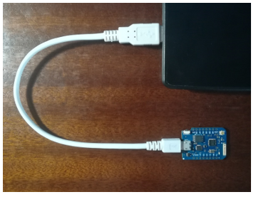 Figure 1: Photo of Master Node connected to a laptop.
3.1. Hardware Description
As mentioned before three types of nodes were used: a master node, static nodes and robot nodes. Master node and static nodes are composed by D1 mini pro boards with a wireless antenna Wi-Fi ESP8266, and a power supply. In the case of the master node the power supply was the PC it was connected to, in the case of static nodes a power banks were used.
Figure 1 is a photo of the master node used, connected to a laptop where the end user could send commands and received information from the network. Figure 2 is a photo of a static node used, which served the purpose of acting as a relay and extending the network.
The robot nodes were two wheeled mobile robots composed by a NodeMCU 1.0 board also with an ESP8266 module, a L293 Motor Driver Shield, two rubber wheels with Micro DC geared motors and a power bank, that served as a power supply. The robots are completely similar in terms of hardware with just small differences in how the boards were mounted as can be seen in Figure 3 and Figure 4, which are photos of the first and second Robot Nodes used respectively.
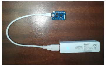 Figure 2: Photo of a Static Node.
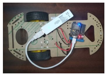 Figure 3: Photo of the first Robot Node used.
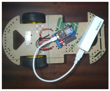 Figure 4: Photo of the second Robot Node used.
All the boards in each node were programmed using the Arduino programming language and respective Arduino IDE. The Arduino programming language makes use of two functions that are always present: setup and loop. Setup runs once when the board is connected to an energy supply. Loop runs continually after the setup, as long the board is connected to an energy supply. Future mentions to setup and loop, while explaining the code, refer to these two functions. The robots need to perform several tasks periodically, such as measuring the RSSI or moving. To achieve this behavior the Task Scheduler library was used.
3.2. Wireless Sensor Network Implementation
To manage creation of the wireless sensor network and communication between nodes the painlessMesh library was used [13]. This library uses the esp8266 hardware present in the boards to create a mesh network. The painlessMesh library does not use the Arduino WiFi libraries, due to performance problems, but the native esp8266 libraries [13]. The library allows us to make the nodes to communicate with each other, in a prototype of a WSN, without concern about how to structure or manage the network. The great advantage of using this library is that any operational nodes will automatically self-organize into a functional mesh network.
The messages between nodes are all JSON objects, which makes them human readable and facilitates integration with frontends and other applications. The mesh does not use or create a TCP/IP network, rather each node is identified by a 32bit chipId obtained through the esp8266 native SDK. As a result, every node will have a unique id, that can be used to communicate specifically to that node. Broadcast messages to all nodes in the mesh are also possible [13].
Some functions of the library are used in the setup of every node, namely init, which initializes the mesh, and the functions that set up callbacks, such as onReceive(&receivedCallback) and onNewConnection(&newConnectionCallback). The functions given as arguments: receivedCallback and newConnectionCallback, are present in every node as well. They execute when a message is received by the node and when a new node connected to the network, respectively.
Other functions used at setup are setRoot for the master node and setContainsRoot, for all others. The purpose of these is to avoid the creation of submeshes during mesh formation. It makes sure all nodes know the gateway is the master node and a node once connected to the master node will not disconnect. This is necessary because of a limitation during mesh formation, namely that each node can only connect to another one node at any given moment. Because of this, nodes will try to randomly connect and disconnect until a full mesh is formed. This solution works but may create submeshes. The functions above aim to solve this problem. Another consequence of the “each node can only connect to one other node at a time” will be that usually only node of the mesh will be available to connect to other nodes.
A library function used in the loop of every node is the function update, which runs maintenance tasks and is required for the mesh to work. In the master node it is also used the subConnectionJson function, which allows to print the mesh topology in JSON format. All nodes use the sendSingle and sendBroacast functions. The former allows to send a message to a node using its chipId, the latter sends a message to all nodes in the mesh.
Task Scheduler
The Task Scheduler library allows for periodic task execution. It is possible to specify execution period, in milliseconds or microseconds, and number of iterations, be they finite or infinite. The reason for needing to use this library is that the boards used cannot launch several threads at a time, hence cannot multitask with recurring to external libraries.
It works by first creating a scheduler using the Scheduler class. Then creating tasks using the Task class, and specifying the execution period, number of iterations and the actual function that will define the task behavior. Then at setup each task is added to the scheduler. From there on it is possible to enable or disable tasks as required [14]. The two main tasks used by the robot nodes are the RSSI Task and the Moving Robot Task.
The RSSI Task’s main purpose is to measure the RSSI value. It will always do this if the scan for Wi-Fi networks is successful. Then depending on flags active it might just send this value to the master node or check if this value is lesser or equal to the RSSI threshold. If it is smaller, meaning more negative because the RSSI value is usually a negative integer, then it will send the RSSI value to the master node along with a request to place a new node. If the RSSI value is not smaller the robot can move further, and so it will call the appropriate movement function, disable the RSSI task and enable the Robot Moving task.
The Robot Moving Task’s main purpose is to time the movement of the robot and send the RSSI value to the master node once a movement is finished. It is also used to create the robot node auto movement, as will be explained below.
The RSSI value is the most important metric in the prototype because it is based on it that the robot nodes will decide when a new node should be placed. Therefore, it regulates the extension of the WSN. It will also be used later both in the cooperation between robot nodes and in their response to deployment of new static nodes.
RSSI Request
It is useful to measure the value of the RSSI to understand how it changes, particularly due to growing distance from the master node. With this purpose in mind was created a way to simply have the master node send a request to a robot node and have the robot measure the RSSI and send its value back to the master node, to be printed and made available to the user.
The laptop connected master node expects user info from the serial monitor of the Arduino IDE. If the input received is the, case insensitive, string “RSSI” it will send a RSSI Request to all nodes. This request is simply a message that will prompt each node to enable the RSSI Task, which will make it measure the RSSI value, and then send this value back to the master node. The master node will print the value and an identifier of the node that sent it. Algorithm 1 represents the algorithm behind RSSI requests.
In terms of number of messages exchanged within the network, they are at least , where is the total number of nodes in the network. The reason for this number is that the master node will send a broadcast message upon being prompted by the user with an RSSI Request, so it will send a message to all nodes except itself, . Every node will then measure the RSSI and respond to the master node, so this number is doubled. Depending on the extension of the network this number will increase because the message may need to hop between nodes before reaching the master node.
| Algorithm 1: RSSI Request | |||||
| Result: The Master Node will print the RSSI values for all nodes in the network in its serial monitor | |||||
| Initialization; | |||||
| while Master Node on do | |||||
| Expects user input; | |||||
| if User input = RSSI then | |||||
| Send RSSI Request; | |||||
| Nodes send RSSI values;
Print RSSI values; |
|||||
| end | |||||
| end | |||||
4. Testbed Deployment
With the testbed ready it is possible to start developing algorithms that will create us a prototype for an autonomous, extensible WSN. With this in mind, firstly it is necessary to develop ways of having the robot node move on its own and request new nodes for the network once a RSSI threshold is hit, which was called AutoMOV. Furthermore, ways of having two robot nodes cooperate with each other, to further extend the WSN, were developed, which was called RCoop. Finally, there was a need to develop ways for the robot nodes to know when a new static node was deployed and respond accordingly, extending the network if possible, which was called ReStatic. In this section the aim is to present each of these algorithms and explain how they were implemented using the testbed.
4.1. Automovement Algorithm (AutoMOV)
In the first implementation of the WSN prototype the robot node moved by commands sent from the master node by user input. But the goal was autonomous movement and deployment of an extensible WSN. To achieve this the robot nodes need to move autonomously, not prompted by user input, so an algorithm for robot node automovement was developed, hereinafter referred to as AutoMOV. All movement at this point occurs along a line.
An auto movement request is made if the Master Node catches a string that starts with ‘A’ or ‘M’. This calls the function AutoMOVRequest. This function will print if the request is to start auto movement (A) or to stop auto movement and go back to manual (M). It will also send the given string to the robot node by method sendMessage. The method sendMessage uses the communication functions from the Painless Mesh library, sendSingle or sendBroadcast, but with arguments to choose between them.
The robot node responds to this sendMessage with the call-back routine receivedCallback. In the case of ‘A’ it will turn the movement type to ‘F’, which will make the robot move forward, this is the case because all movement occurs along a line at this point. Later it should decide the movement type based on sensor information.
It will also activate an AutoMOV flag and enable the RSSI Task. In the case of ‘M’ it turns off the AutoMOV flag and stops movement.
| Algorithm 2: Automovement (AutoMOV) | |||
| Result: Robot Node performs discrete movement until it hits its RSSI Threshold | |||
| Initialization;
while Master Node on do Master Node expects input if User input = M do AutoMOV Stop Request; Robot Node stops; else if User input = A do AutoMOV Start Request; while Current RSSI <= RSSI Threshold do Robot moves; end end |
|||
| end | |||
The RSSI Task will then be responsible for making the robot always move unless the current RSSI is equal or below the threshold, which would make AutoMOV stop and the robot node to send a request to the master node, for placement a new static node. Otherwise it enables the Moving Robot Task. This last task has an extra ‘if’, to deal with auto movement, that basically says: if one movement was completed and the AutoMOV flag is on, then it will enable the RSSI Task again. This creates a loop between the two tasks. Algorithm 2 represents the algorithm behind AutoMOV requests.
4.2. Robot Cooperation Algorithm (RCoop)
Coordination between multiple robots, cooperating in deployment or exploration, is seen as an important concern by current WSN literature [3-6]. With this purpose in mind there is a necessity for algorithms that allow multiple robots to cooperate and for field tests involving more than one robot [4][6][7].
The goal then was to develop an algorithm that allows two robots to cooperate in a prototype of WSN deployment based on communication metrics, namely the RSSI. Hereinafter this algorithm will be referred as RCoop.
The two robot nodes were named Robot One (R1) and Robot Two (R2) to help differentiate between them. The only real distinction between robot nodes is that R1 will be the first to move. All movement described occurs along a line.
R1 will be sent a signal from the user and start movement. Each robot movement is time limited to ten seconds. After these ten seconds of movement it will measure the RSSI and based on this value decide to stop or move again. While the RSSI is above a certain threshold it will continue to perform discrete ten second movements. If the RSSI is found below the threshold it will stop, ask for the deployment of a static node and send a message to R2. Deployment of static nodes is done by human agents at this point. The reaction of robot nodes to the deployment of static nodes will discussed later. Here the main concern is about how the robots can cooperate.
R2 after receiving the message from R1 will know the first robot has reached the RSSI threshold and so commence its own movement. The message sent by R1 basically functions as R1 ‘calling’ R2. R2 will mimic the behavior of R1 and move until it has reached the RSSI threshold. When R2 reaches the threshold, it will send a message to R1. This will prompt R1 to update its own threshold and start moving again. The goal here is to extend the network as much as possible using the two robot nodes.
The way this works in terms of code is that R1 will first be sent an AutoMOV request by the master node. It will normally follow AutoMOV until the threshold is reached. When it reaches the threshold, it will call AutoMOVRequest, which will send a message to R2. R2 will expect a message with this format via the callback routine receivedCallback and will activate its own AutoMOV because of it. R2 will then perform AutoMOV, as explained above, until it reaches its threshold. When at the threshold will send a message to R1 via sendMessage, informing it R2 is at the threshold. R1 will then decrement the rssiThreshold variable and turn its AutoMOV own again, and so move further until it reaches the new threshold value. Algorithm 3 represents the algorithm that deals with robot cooperation (RCoop).
| Algorithm 3: Robot Cooperation (RCoop) | |||
| Result: The two robots will extend the network | |||
| Initialization;
R1 AutoMOV; if R1 RSSI <= RSSI Threshold do R2 AutoMOV; if R2 RSSI <= RSSI Threshold do R1 expands Threshold; R1 AutoMOV; End |
|||
| end | |||
4.3. Response to Static Nodes Algorithm (ReStatic)
The other thing that is required to attain the goal of having an extensible WSN is that the network responds autonomously to the deployment of static nodes. To elicit this behavior, a communication metric is used again, the RSSI.
When a static node is placed it connects to the network normally, then it will measure its RSSI. It will send this value to the mobile robots connected. Then each robot will use this value to decide whether it should start movement or not. This decision is based on if the difference between its own RSSI and the static node RSSI is lesser than the value of the RSSI threshold. If the difference between RSSIs is lesser than the threshold then it means the static node is closer to the master node and hence the network can be safely extended, so the robot will move.
But if a new node connects it usually will connect as a subnode to the nodes already there, so how to solve this problem? The answer was to force a reorganization of the network. If the robot concludes by the above described method that the static node is closer to the master node then, before it initiates movement, it will reset its own board. The result of this is that when the robot reconnects to the network it will now be a subnode of the newest static node in the network topology. The value of the robot’s threshold is saved in the master node, via a message sent by the robot before it resets. When the robot node reconnects the master node sends this value to the robot again, the later will update its threshold and reinitiate movement.
In terms of code this is achieved by using the RSSI Task in the static nodes as well. It will activate and measure the RSSI value as soon as the static node is turned on. Then it will send this value to the master node which will in turn send it to the robot nodes, via sendMessage. As usual the way to prompt behavior in a certain node, the node is made to expect a string formatted a certain way, via the receivedCallback, and if that string is received the desired behavior occurs. So, in that same way, when the robot nodes received the value of RSSI prefixed with the string “(mesh node)” they will first extract the RSSI value from that string. Then, they will check if the deployed static node can be considered closer to the master node, calculating if the difference between their RSSI value and the RSSI value of the static node is greater than their RSSI threshold (currentRSSI – meshRssi > rssiThreshold). If so, the robot node will expand its threshold and send it to the master node. The master node will save this value and send a message back to the robot node signaling the robot can now restart, with the purpose explained above. The robot node will then restart by esp8266 native function, ESP.restart, which will restart the board. The master node will expect a robot node connection via the newConnectionCallback, which is a callback routine that executes each time a new node connects the network. In case there is a saved RSSI threshold value for the robot node that connected then it will send this value to the robot that just connected. The robot will use this value to update its threshold and turn the AutoMOV on, thus extending the network. Algorithm 4 represents the response to static nodes algorithm described above. This algorithm will be known as ReStatic.
| Algorithm 4: Response to Static Nodes (ReStatic) | |||
| Result: Robot Nodes extend network if possible | |||
| Initialization;
Static Node Deployed; Send RSSI to Robot Nodes; if RSSI – Static RSSI > Threshold do Expands Threshold and save it; Robot Node reset; Robot Node receives threshold; Robot Node AutoMOV; |
|||
| end | |||
5. Performance Evaluation
It was then time to put the algorithms to test to verify if the intended behavior of an extensible WSN could be achieved, take measurements, find potential faults or avenues for improvement. For these purposes four scenarios were developed, each progressively testing each one of the developed algorithms, first separately, then in conjunction. As the presented work is still in its initial proposal, some RSSI issues were considered out of the scope. All demonstration scenarios considered an open space area with no obstacles and, as much as possible, a linear variation of RSSI.
The measurements were conducted in an open space indoor area. The master node was connected to a laptop via the USB port and will collect RSSI data. The laptop is placed on a wooden support that measures 31 cm in height. Time and distance are collected by the testers, while RSSI values are registered by the master node.
Firstly, it was important to study the variation of RSSI based on the distance between a robot node and a master node. This would serve to understand how it naturally variates without accounting for any robot node movement and illustrate the relationship between distance and the RSSI value. It makes use of and proves the functionality of the RSSI Request.
The robot node was placed at several distances of separation to the master node, always one meter apart from 0m to 13m. At each distance, the user would elicit the RSSI value through RSSI Request. After collecting ten samples at that distance of separation an RSSI average was calculated. Figure 5 shows the RSSI averages for the various distances of separation to the master node.
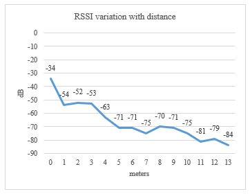 Figure 5: Robot Node RSSI variation with distance from the Master Node.
5.1. Scenario 1: One Robot Node
This first scenario intends to verify how much it was possible to extend the network simply using two nodes: the master node and a robot node. It will also illustrate the functionality of the robot node AutoMOV algorithm.
The robot node is place on the floor at a 0 meters distance from the master node. It will be sent a signal from the master node which will start the AutoMOV. Then, the robot node will perform discrete 10 second movements along a line while measuring the RSSI. When its current RSSI value is below a certain threshold it will stop and request the placement of a new static node. Figure 6 represents the end state for this scenario.
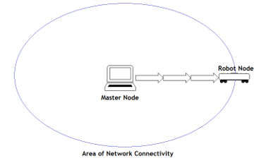 Figure 6: End state for Scenario 1 composed of Master Node and a Robot Node.
After ten trials an average of the values of time since AutoMOV started till robot node stoppage, distance traversed by robot node and last RSSI recorded is calculated. Table 1 holds the recorded values for this first testing using a robot node.
Table 1: Averages of time, distance and RSSI for 1 Master Node 1 Robot Node.
| Time | 54’’ |
| Distance | 4m 83cm |
| RSSI | -68 dB |
5.2. Scenario 2: Two Robot Nodes
The second scenario intends to extend the WSN using two robot nodes. This scenario uses two robot nodes and the master node and is meant to demonstrate the functioning of the RCoop algorithm.
Both robot nodes are placed next to one another at a 0m distance from the master node. Then the user enters ‘A’ into the serial monitor of the master node in the Arduino IDE. This is the signal that will set the AutoMOV of robot node named R1 on. All other network extending behavior is autonomous. Figure 7 represents the end state for this scenario.
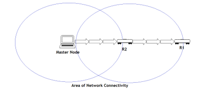 Figure 7: End state for Scenario 2 composed of Master Node and two Robot Nodes.
The last RSSI values of both R1 and R2 are recorded by the master node. The distance of both robot nodes to the master node after both robot nodes stop is recorded. The duration from the time the signal is sent until both robot nodes stop is also recorded. After ten trials an average of RSSI, distance and time was calculated. Table 2 holds the recorded values for this first test with the two robot nodes.
Table 2: Averages of time, distances and RSSIs for 1 Master Node, 2 Robot Nodes.
| Time | 3’ 01’’ |
| R1 Distance | 7m 12cm |
| R2 Distance | 5m 11cm |
| R1 RSSI | -71 dB |
| R2 RSSI | -64 dB |
5.3. Scenario 3: One Robot Node, One Static Node
This third scenario intends to extend the WSN, by guaranteeing the robot nodes will respond to the deployment of new static nodes. So, it serves to test the functionality of the ReStatic algorithm. It does so by using the master node, one static node and only one robot node.
The robot node will be placed at a 0m distance from the master node. Robot node AutoMOV will be turned on by user input and then it will move until it reaches its RSSI threshold. Then, a static node will be place at this threshold. The robot node will respond to this placement autonomously and move again till it reaches a new threshold, extending the network. Figure 8 represents the end state for this scenario.
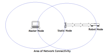 Figure 8: End state for Scenario 3 composed of Master Node, a Static Node and a Robot Node.
The last RSSI value before robot node stoppage is recorded by the master node. Time until robot node stoppage and maximum distance from static node are recorded by human users. After ten trails an average of these values is calculated. Table 3 holds the values for this first test that uses a static node.
Table 3: Averages of time, distance and RSSI for 1 Master Node, 1 Robot Nodes, 1 Static Node.
| Time | 3’ 40’’ |
| Distance | 7m 1cm |
| RSSI | -73 dB |
5.4. Scenario 4: Two Robot Nodes, One Static Node
Finally, the fourth scenario allies the RCoop algorithms and the static node response algorithm. For this last scenario a master node, two robot nodes and one static were used.
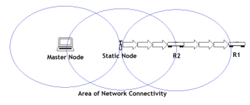 Figure 9: End state for Scenario 4 composed of Master Node, a Static Node and two Robot Nodes.
The procedure is similar to the two robot nodes test except that a static node is place at the R2 threshold when both robot nodes and stopped. So, both robot nodes are placed at 0m distance from the master node. A signal is sent to R1 by the user from the master node. Then, robot node AutoMOV and RCoop occur autonomously. Finally, a static node is placed at the R2 threshold and the robots will identify it and move again to new thresholds. Figure 9 represents the end state for this scenario.
The last RSSI values before robot node stoppage for both robot nodes are recorded by the master node. The time from signal sent to R1 till the network stops extending is recorded by a tester. Final distances of each robot node to the master node are also recorded by a tester. After ten trials an average of RSSIs, distances and time was calculated. Table 4 holds the values for this final test that incorporates all the node types: master node, robot node and static node.
Table 4: Averages of time, distances and RSSIs for 1 Master Node, 2 Robot Nodes, 1 Static Node.
| Time | 4’ 33’’ |
| R1 Distance | 11m 50cm |
| R2 Distance | 6m 76cm |
| R1 RSSI | -82 dB |
| R2 RSSI | -71 dB |
6. Discussion
First, it is important to have an idea of how to expect the RSSI to change with growing distance from the master node, this is the purpose of the RSSI – distance test. It is expectable that RSSI value decreases with distance from the master node, seeing as at 0m the RSSI value is -34dB and at 13m distance the RSSI is -84m. But this variation is not linear, so it must be assumed that there are other factors contributing to RSSI change besides distance.
Distance reached by the robot nodes is a key factor in knowing if the purpose of the algorithms was fulfilled and the WSN is extending. If only the number of nodes used is considered, it is expected the distance from the master node will increase with the increase in the number of nodes used, as the WSN can extend itself further. In this case the one robot test would give us the least distance, with just one node used, and the two robot nodes and one static node test would give us the furthest distance, with three nodes used. Figure 10 shows us the distances obtained according to the numbers of nodes used. It is then verified that the network is extending itself through the programmed behavior of the robot nodes.
Time was considered of less importance at this point in testing. Still it is noted a big increase, going from an average 54 seconds with one node to 4 minutes 33 seconds with three nodes. The way of reorganizing the mesh network, by resetting a robot node when a suitable static node is detected, should be reviewed. The current solution causes a lot of overhead.
Using a communication metric such as the RSSI gives rise to some problems. First off, must be said that when considering the RSSI threshold as the point where a robot node should stop and request a static node, this is a virtual limit. It is not exploring the actual hardware limit of the communication module, the wireless antenna Wi-Fi ESP8266. Explorations on RSSI variations using ESP8266 modules have used distances of up to 140m between a station and an AP and still reach acceptable values for RSSI [15]. These experiments were performed outdoors whereas the ones here were indoors, but they give an idea of the distances that could be reached if the limits of the hardware were explored. The aim here however was to develop algorithms that could generate the intended behavior on the prototype, namely the creation of an extensible WSN. Although it is legitimate to consider that testing the present proposal at the hardware limits would be interesting and closer to a live deployment scenario.
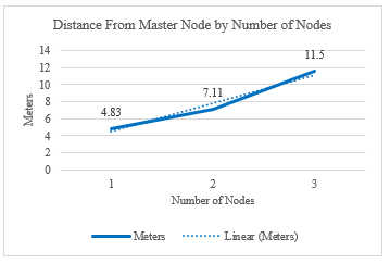 Figure 10: Variation of distance from the Master Node with number of nodes used in the WSN.
Finally, it is important to consider how the problems in expanding the RSSI threshold to make the robot nodes move further. Firstly, there is a need to find a better way to judge the distance of the static nodes when deployed. Deployment of several static nodes in proximity, or the same static node disconnecting from the network and then connecting again, might impress false information on the robot node, prompting it several times to move further. Secondly, saving the current threshold of the robot nodes in the master node when it resets could be problematic if the robot node disconnects from the network more than one time. This problem also arises from the method of reorganizing the network through resets of robot nodes. Even as it stands there might be a better way for the robot node to judge its threshold from the network topology and its own RSSI measurements, instead of receiving it from the master node.
7. Conclusion and Future Work
WSNs are ever more prevalent in modern living. Many applications, such as in disaster situations, require impromptu deployment of a WSN. Therefore, it is important to explore ways of WSN deployment. The usage of mobile robots to aid in this development is also important because it avoids the necessity of human agents. Coordination between mobile robots is essential in deployment and exploration tasks.
With this in mind a prototype of a WSN aimed at creating an extensible wireless network and proved it possible, within certain assumptions, using cooperation between mobile robots and responsiveness to the deployment of static nodes.
As for future work it should be interesting to test the solution proposed here with the actual hardware limits of the ESP8266 wireless module. Also, there is a need to develop a better way to manage network connections, even if that means foregoing the painlessMesh library and using the native ESP8266 SDK. Within the solution here, a better way to manage the RSSI thresholds of the robot nodes might also be a good avenue for new developments. Testing the WSN prototype with sensors able to capture environmental data would also prove interesting and open new avenues of exploring, such as how to effectively route sensing data.
Conflict of Interest
The authors declare no conflict of interest.
Acknowledgment
This work is funded by FCT/MCTES through national funds and when applicable co-funded EU funds under the project UIDB/50008/2020. The authors would like to acknowledge the company InspiringSci, Lda for the interest and valuable contribution to the successful development of this work.
- J. Amaro, I.D.L.T. Diez, M.L.P. Joao, S. Vasco, J. Galan-Jimenez, “Protótipo de uma Rede de Sensores Sem Fios para Implantação Robótica de Percurso: A Prototype of a Wireless Sensor Network for Robotic Path Construction,” Iberian Conference on Information Systems and Technologies, CISTI, 2020-June, 20–25, 2020, doi:10.23919/CISTI49556.2020.9141080.
- S. Stage, P. Report, S. Kumar, R. No, C. Science, “Design and deployment of Wireless Sensor Networks,” 313–325, 2017.
- Y. Sankarasubramaniam, E. Cayirci, others, I.A.. Su, “A survey on sensor networks,” IEEE Communications Magazine, 40(8), 102–116, 2002.
- A. Chattopadhyay, A. Ghosh, A. Kumar, “Asynchronous Stochastic Approximation Based Learning Algorithms for As-You-Go Deployment of Wireless Relay Networks Along a Line,” IEEE Transactions on Mobile Computing, 17(5), 1004–1018, 2018, doi:10.1109/TMC.2017.2750147.
- T. Suzuki, R. Sugizaki, K. Kawabata, Y. Hada, Y. Tobe, “Autonomous deployment and restoration of Sensor Network using mobile robots,” International Journal of Advanced Robotic Systems, 7(2), 105–114, 2010, doi:10.5772/9696.
- G. Tuna, V.C. Gungor, K. Gulez, “An autonomous wireless sensor network deployment system using mobile robots for human existence detection in case of disasters,” Ad Hoc Networks, 13(PART A), 54–68, 2014, doi:10.1016/j.adhoc.2012.06.006.
- A. Chattopadhyay, M. Coupechoux, A. Kumar, “Sequential Decision Algorithms for Measurement-Based Impromptu Deployment of a Wireless Relay Network Along a Line,” IEEE/ACM Transactions on Networking, 24(5), 2954–2968, 2016, doi:10.1109/TNET.2015.2496721.
- H. Liu, J. Li, Z. Xie, S. Lin, K. Whitehouse, J.A. Stankovic, D. Siu, “Automatic and robust breadcrumb system deployment for indoor firefighter applications,” MobiSys’10 – Proceedings of the 8th International Conference on Mobile Systems, Applications, and Services, 21–34, 2010, doi:10.1145/1814433.1814438.
- R. Soua, L. Saidane, P. Minet, “Sensors deployment enhancement by a mobile robot in wireless sensor networks,” 9th International Conference on Networks, ICN 2010, 121–126, 2010, doi:10.1109/ICN.2010.29.
- N. Zhou, X. Zhao, M. Tan, “RSSI-based mobile robot navigation in grid-pattern wireless sensor network,” Proceedings – 2013 Chinese Automation Congress, CAC 2013, 497–501, 2013, doi:10.1109/CAC.2013.6775785.
- O.M. Elfadil, “Navigation algorithm for mobile robots using WSN,” Proceedings – 2013 International Conference on Computer, Electrical and Electronics Engineering: “Research Makes a Difference”, ICCEEE 2013, 554–559, 2013, doi:10.1109/ICCEEE.2013.6634000.
- A.C. Jiménez, S.J. Bolaños, J.P. Anzola, “Decentralized model for Autonomous Robotic Systems based on wireless sensor networking,” ARPN Journal of Engineering and Applied Sciences, 11(19), 11378–11382, 2016.
- painlessMesh / painlessMesh · GitLab, Jul. 2020.
- GitHub – arkhipenko/TaskScheduler: Cooperative multitasking for Arduino, ESPx and STM32 microcontrollers, Aug. 2020.
- Yoppy, R.H. Arjadi, H. Candra, H.D. Prananto, T.A.W. Wijanarko, “RSSI Comparison of ESP8266 Modules,” 2018 Electrical Power, Electronics, Communications, Controls and Informatics Seminar, EECCIS 2018, 150–153, 2018, doi:10.1109/EECCIS.2018.8692892.