
BrcLightning – Risk Analysis and Scaling for Protection against Atmospheric Discharge – Extender
Volume 6, Issue 1, Page No 1384-1402, 2021
Author’s Name: Biagione Rangel De Araújoa)
View Affiliations
BRC – Biagione Rangel Consulting, Natal, ZIP Code: 59064-490, Brazil
a)Author to whom correspondence should be addressed. E-mail: contato.brc@biagione.com.br
Adv. Sci. Technol. Eng. Syst. J. 6(1), 1384-1402 (2021); ![]() DOI: 10.25046/aj0601158
DOI: 10.25046/aj0601158
Keywords: Risk Analysis, Lps Sizing, BrcLightning

Export Citations
This manuscript intending to publicize the improvements incorporated in the BrcLightning application, including the Risk Analysis module with the help of a pop-up, which provides the result and assists in the identification of mitigating measures by the professional, which must be defined to reduce the calculated risks. Other points addressed in this extension are the improvements added to the database to meet the corporate demands of companies, referring to the Risk Analysis module. It also incorporates flexibilities to perform the sizing separately, in the design, evaluation and scaling modules of the LPS – Lightning Protection System that using rolling sphere method and Angle Method, incorporating, in some of the modules, the issue of opinions or alerts. These modules use the mathematical approach methodology. In addition to these improvements, this review included the reporting module of facilities in the filter system, which allows the use of the database more selectively for the emission of these documents. This filter has a structure for issuing corporate demands of reports. The results can be obtained quickly and easily, on-screen or printing several reports. The reliability and safety of the results can be assessed through the check with the examples of the standards that define the criteria and methodology, that must be followed to carry out for cases of Risk Analysis or through graphic drawings on AutoCad platform or similar for the sizing modules. Other improvements in this extension are the addition of topics for new modules for which we already have the equations modeled in Excel, although we have not yet coded in the programming language.
Received: 21 December 2020, Accepted: 09 February 2021, Published Online: 28 February 2021
1.Introduction
This article is an extension of the work originally presented at the Symposium SIPDA XV [1]. In the event, representatives of a large company attended our explanation and reported that the great difficulty they faced was to have the control and traceability of the various Risk Analyses that are performed for each building or structures of the various units of the company. So, considering that our system is structured in the form of a database, we evaluated that, by introducing structural changes in this database, it will be possible to meet this demand.
Concomitantly with this observation, we also identified that other improvements would be required, even to use the various modules of the system in isolation (before having to register a project), either in the database or through an app which may be via mobile phones. These improvements aim to meet specific demands, such as those to evaluate the effectiveness of the volume of protection of a given SPDA concerning the various structures or equipment and facilities that, in principle, are or would be under protection against direct impacts of atmospheric discharges. In this case, the data is not embedded in the database but can be consolidated into a report, with options to be printed or archived.
Regarding the Reporting Module, this extension was less extensive, as it was composed by the improvements of the filters defined to facilitate the selective issuance of Database Reports, with limited coverage of the specificity of each module that make up the current system. However, because it is a database, we intended (in a new version) to provide tools in this module, to enable the data export specifically to the Excel environment, to allow better tools for analyzing historical data.
- Definitions
- Coverage radius (rc): The distance between the point of the cover margin, of a determined envelopment of an LPS. This distance determines the size of the horizontal projection of the fictitious plane, given by equation (1):
rc = [h1(2R – h1)]1/2 – [h2(2R – h2)]1/2 (1)
where:
rc horizontal protected distance
h1 height of the higher mast
R rolling sphere radius
h2 height of the lower mast:
- Cover margin height (hc): The dimensions of the height of the nearest point on the envelope over the structure under the protection of the LPS;
- Distance from the critical point (d1): The distance between the critical point and one metallic element such as rods or wire air-terminations
- Envelopment: Geometric shape that limits the protected volume according to the rolling sphere method;
- Coverage margin (cm): The shortest distance between a point of the structure under the protection of the LPS and the envelopment of the protective volume. The dimension of the margin corresponds to the perpendicular tangent measurement of the envelopment to the nearest point of the structure under protection. The graphical representations of “cm” are as shown in Figure 1a, Figure 1b, and Figure 1c (all contained in Figure 1):
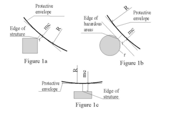 Figure 1: Examples of coverage margins
- Fictitious plane (Fp): Assumed horizontal plane that provides coverage of protection at a given height;
- Hazardous areas: Area surrounding storage facilities or transfer station of flammable liquids or gases, due to the possibility of containing flammable or explosive mixtures. They are defined in: Zone 0 (when the explosive/inflammable mixture is still there or will be for long periods); Zone 1 (likely to occur in normal operating conditions) and Zone 2 (it’s unlikely – an abnormal condition of operation);
- Sizing module marks: The marks indicated in the graphs of the sizing and limit variation modules correspond to the extreme points of the structure that should be protected or evaluated on the effectiveness of the coverage by the SPDA protection wrap, as shown in figures 2 and 3 below:
 Figure 2: Hazardous areas limiting point figure (see Figure 1b)
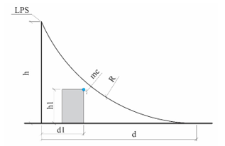 Figure 3: Structure limiting point figure (see Figure 1a)
- Software Development
The application is developed in Access, in VBA language, to allow it to run on Windows and on the Internet. We had a project to carry out the migration to an Internet language; however, due to the Covid 19 pandemic, we had to cancel it. Nevertheless, we hope that, considering the problems due to the current situation, we can resume the project in the year 2021.
In this version, the system continues with the same configuration of modules and sections of the previous publication, from which this paper is an extension of (SIPDA XV [1]). Thus, we will focus on detailing the improvements that have been introduced, as described in sequence (items 4 to 7).
- Risk Analysis Module
Risk Analysis consists of 5 sections: 1. Registration Module; 2. Zone Registration Module; 3. The configuration data of the connected lines and Zone.; 4. Risk Analysis Factors Module (typical loss value) and 5. Results Module.
4.1. Registration Section
In this section, there are specific data related to design registration that can be common to all modules and all sections, but also, there are important data specific to the Risk Analysis Module. Due to this, we have identified that it will be more effective for these data input to be dismembered in two modules: one for general project registration and another for registration and configuration of the Risk Analysis Module. However, this should only be performed in a new version.
The improvements that we introduced in this section included the fields of input to meet the demand to perform the registration of organizational structures, containing up to 5 levels: Level 1 – Hold Company; Level 2 – The Business Unit, which may or may not cover several other Operating Units; Level 3 – The Operational Unit; Level 4 – The Operational Sector and Level 5 – The installation subject to risk analysis or the one containing Air Terminal. This improvement is only incorporated into the Registration Form of this Section. Therefore, in this version, it has not yet been possible to integrate this organizational structure registration with the other modules, including the Risk Analysis Module itself, regarding the reports. This requires numerous changes in the reports already formatted. The reported modifications are highlighted in green as shown in Figure: 4.
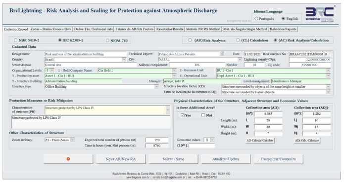 Figure 4: Main screen of data input
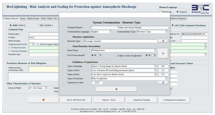 Figure 5: Screen for customizing structure and zones)
4.2. Zone registration module
The System was engineered to cover up to 5 Zones (NBR-5419-2 [2] and IEC 62305-2 [3] do not establish limits, but provide examples of up to 5 Zones), as we observe that this is a practice used and that already surpasses the examples provided by the standards cited. The number of Zones is selected as shown in Figure 4 (Zone in Study).
The System already makes several types of structures available, which were understood as necessary and sufficient to meet the range of facilities and buildings that must be studied and related to each of them, the different types of Zones. However, the Designer can insert new structures and new zones, but he or she must proceed to register them. To do so, it will be necessary to customize them and make the association with the loss factors, as shown in Figure 5.
In this Section, the designer inserts the data for each zone that is defined for Risk Analysis, according to Section One of the Register, as shown in Figure 4. In this section, no improvement has been introduced, as show in Figure 6. For more details see SIPDA XV [1].
 Figure 6: Screen of the setting module of the Zones (structure with all 3 Zones)
 Figure 7: Setting screen of the connected lines and other zone data
4.3. The setting data of the connected lines and Zone
This Section provides the space to enter information about power lines and telecommunications lines: how they connect to the site (building; installations; etc.). The designer can also enter protective measures due to touch and step voltage and other risk-mitigating measures, individually for each defined Zone. In this section, it was introduced improvements to the Help pop-up form with the result of the risk analysis, as shown in Figure 7. Thus, the designer can monitor the effectiveness of each mitigating measures in real-time. This pop-up, once visible, can be viewed in all sections of the risk analysis module.
Also, there is a pop-up to help define line parameters and other alert parameters as shown in Figure 8.
4.4. Risk Analysis Factors Module
This section presents the typical loss values for each zone (as shown in Figure 9), based on the definitions established in section one (as shown in Figure 4) and two (as shown in Figure 5).
 Figure 8: The pop-up helps with line parameters and other information
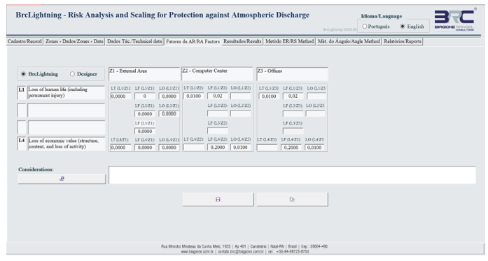 Figure 9: Loss Type Factors Module Screen
In the version presented in SIPDA XV [1], it was already possible for designers to change the typical loss value, if they had another interpretation regarding the one previously defined in the system (these factors defined in the system were based on the definitions established in NBR 5419 -2 [2] and IEC 62305-2 [3] for typical loss values). In this case, in the previous version, the designers had to standardize their basic values for each type of installation in advance. The improvement introduced allows that, in case they don’t have a database parameterized with the values according to their interpretation criteria, they can do so by simply selecting the designer parameters (in the input field) and applying a double click on each factor that they want to parameterize. This way, a pop-up (as shown in Figure 10) form will appear for each factor and they will define it at their discretion. The new defined typical loss value, after being updated, will be highlighted in green (as shown in Figure 10), but there are security restrictions and other requirements (see item 9.4).
4.5. Results Module
In this section, the final result is as shown in Figure 11. Mitigating measures can also be inserted (the description of these measures), if the results indicate that this is necessary. Mitigation measures, as needed, can be included (these should be inserted descriptively). A technical note with the analysis design also can and should be inserted. Another improvement is the possibility of issuing, in a summarized format, the risk analysis report, as shown in Figures: 12 (a) and (b). This report contains the basic information of the risk analysis study and the result.
 Figure 10: Loss Type Factors Module Screen with individualization pop-up
 Figure 11: Result Module Screen and the button for printing the summarized report
 Figure 12 (a): Summary of risk analysis report (first page) (b): Summary of risk analysis report (last but one page)
 Figure 13: Example of calculation of h x d for Class IV
 Figure 14: Sizing of the Isolated LPS, without hazardous area
 Figure 15: Pop-up for supplementary data
- Rolling sphere module
This Module maintains the 4 Sections of the original version presented in SIPDA XV [1] and is in accordance with NBR 5419-3 [4]; IEC 62035-3 [5] and NFPA 780 [6]. However, the possibility of performing the sizing separately and the printing of the report of this dimensioning was introduced in all four sections. This can be seen in the sequence. Other improvements have been introduced and are detailed in each of the sections.
5.1. Section for sizing ‘h’ or ‘d’
In the version presented in SIPDA XV [1], the system included one graph related to the calculation of the protected horizontal distance at ground level or on a reference surface when the height of the LPS is known and another for the calculation of the height, required to provide protection of a horizontal distance at ground level or a reference surface. Now, these graphs have been integrated into one (as shown in Figure 13). When calculating the height, it is a non-standard commercial value, this version provided an input field to adjust the calculated height. In addition, it was added the option for issuing the report of this dimensioning.
In this section, the height of the insulated LPS is scaled (mast or air termination system of the insulated (only one) overhead wire to protect a specific structure) based on the required LPS Class and the determined coverage margin, including the characterization of a structure with or without hazardous area, as shown in Figure 14. Improvements were also incorporated to print the report of the sizing (the button with the printer icon) and the option to scale the LPS of a database design or a separate design for the issuance of the report, it is necessary to provide additional data, as shown in Figure 15 (in the case of a separate project). The pop-up appears when the print button is pressed. The issued report is shown in Figure 16. Separated projects are not saved in the database.
When the design definitions of the structure to be protected (‘h1’ and ‘d1’, besides ‘mc’) do not allow the sizing of the LPS to the defined protection Class, the System issues an alert of the impossibility of sizing and indicates the limit of the maximum distance and height the structure can be protected by LPS, as shown in Figure 17.
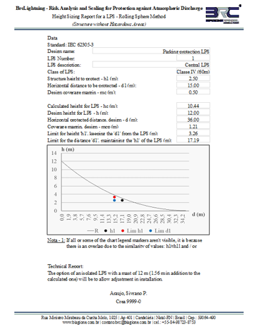 Figure 16: Example report of sizing the isolated LPS
 Figure 17: Alert for impossibility of isolated LPS sizing
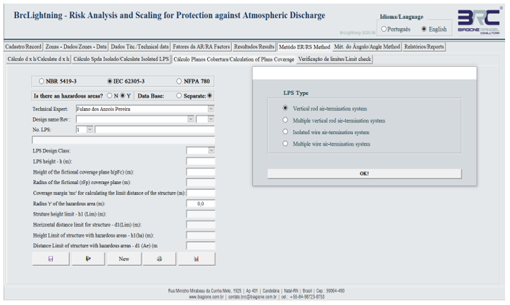 Figure 18: Screen with pop-up to define the LPS type
 Figure 19: Calculation of the Fictional Coverage Plan with alert
5.2. Evaluation section of the limits of an installed LPS
This last section of the Rolling Sphere Module is intended to assess the protection that a specific LPS can provide, considering all the Classes of Protection established by NBR-5419-3 [4]; IEC 62305-3 [5] and NFPA 780 [6]. Improvements have been made to the definition of the LPS type and alert with a technical note, as shown in Figure 20.
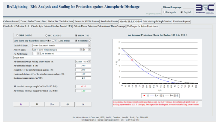 Figure 20: Limits evaluation module screen
- Angle Method Module
This module maintains the three Sections of the original version presented in SIPDA XV [1] and in accordance with NBR 5419-3 [4]; IEC 62035-3 [5]. However, it was introduced in all of them the possibility to carry out the sizing separately and printing the report of this. Considering that this method is not widely used, only an improvement was introduced, in addition to those reported above, in Section 1, as detailed below.
6.1. Height or Distance Sizing (Angle Method)
This Section calculates the horizontal distance protected at ground level or from a reference surface when the height of the LPS is known. It also allows you to calculate the height required for an LPS when you know the horizontal distance that needs to be protected, as shown in Figure 21.
 Figure 21: Calculation of the height x distance
 Figure 22: Calculation of the height x distance – Alert
 Figure 23: Calculation of the height x distance with alert
In order to comply with NFPA 780 [6], the improvement for converting units of measure in meters was introduced, as shown in Figure 23.
The system for this calculation only allows input in meters, thus, with this improvement, it becomes possible to insert the values in feet unit. To do so, two clicks are applied in the input field and one pop-up appears (as shown in Figure 23), providing an input field with the unit in feet. After this, when the pop-up is closed, the unit of measurement in meters. In case of exceeding the suggested limit, an alert will be issued.
- Report Module
This Module includes options for the various preformat of reports that the system, currently, can provide: Risk Analysis Report; LPS project report by Rolling Sphere Method; Module Report using angle method, etc. The system screen where these options are available is shown in Figure 24 and several report templates are shown in Figure 25a Figure 25b. The improvements introduced in this module were composed by the increase in filter options to allow for more appropriate selectivity and the inclusion of the project revision number, as shown in Figure 24.
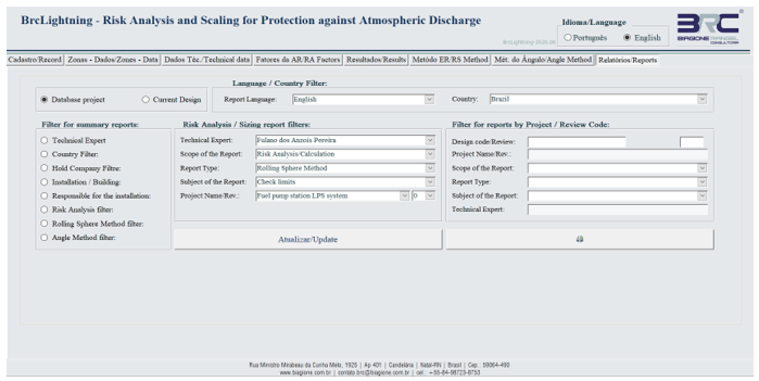 Figure 24: Screen of the reporting module
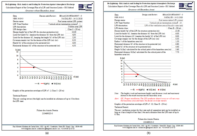 Figure 25 (a): System report templates formatted without hazardous areas (b): System report templates formatted with hazardous area
- Improvements already identified for future insertion
8.1. Module for sizing the surge protective device
Considering that one of the most important mitigating measures identified in the Risk Analysis is the installation of Surge Protective Devices – DPS, it was understood that the inclusion of a module to meet this need is extremely important and, as the methodology and formulas already exist and are supported by NBR-5419-4 [7] and IEC 62305-4 [8], the insertion of a module with this function was included in the planning of future improvements.
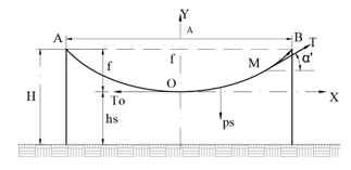 Figure 26: Efforts in wire air termination with supports of the same height
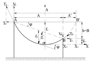 Figure 27: Efforts in wire air termination with supports of different heights
8.2. Module for sizing wire air-termination support structures
Considering that many of the SPDA systems are composed of wire air-termination, it was identified that it is convenient to have a tool to scale the efforts requested from supports of this kind of captor, especially when there is variation in room temperature. Considering, also, that the guarantee of the volume of protection derives from a projection of the height of a captor element and that the control of this lowest point is critical. So, equations were developed to calculate these efforts from the catenary arrow that is required for the wire air-termination. Therefore, it was reversed the practice of calculating this type of sizing, where the effort is calculated and after that, the arrow of a catenary of the cable is calculated. The developed equations include both for supports for the same height and different heights, as shown in Figure 26 and Figure 27. However, these equations are not yet coded in a programming language.
The mathematical approach to dimension the efforts in the wire air-termination was developed in a spreadsheet and the results are in tables such as the Table 1. Other temperature ranges are possible. This is for information only.
8.3. Module to consolidate the list of materials of a project
The insertion of the LPS type in the sizing sections already allows to insert in the database the list of materials. Thus, it will be possible from commercially standardized systems to associate the spare parts list required for that dimensioning, when applicable. This module should have a restricted section to address the material list of grounding systems. There is no prediction to perform the calculation of grounding systems because several software are already dedicated to this purpose. Hence, the module includes only the integration of materials to the LPS design.
8.4. Module for sizing parallel wire air-termination system
We already have several mathematical models responsible for sizing this kind of LPS by parallel wire air-termination in several configurations for this type of systems, as shown in Figure 28 and Figure 29 (other details can be found in the XIII SIPDA [9]). However, we do not yet have the conversion of equations into programming codes, but this is not the biggest problem for insertion. The understanding is that the greatest difficulty is to develop the graphic formulation because it is more complex and I still do not have training in this area, and the addition of this qualification will require planning.
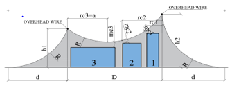 Figure 28: Representation for different levels of parallel wire air termination
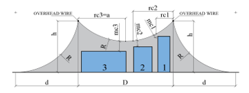 Figure 29: Representation for equal levels of parallel wire air termination
The mathematical approach to determine the limits of a parallel wire air-termination design, considering a possible unevenness of the terrain – at the time of the project implementation or spacing between the wire air-termination or both – produces a table as the one presented in Table 2. This is only an example.
Table 1: Calculated forces for the wire air-termination
| Span: 20,30 (m) |
Arrow of a catenary: 0,20 (m) |
Length: 20,30 (m) | Reference temperature: 26ºC | ||||
| Item |
Temp.: (ºC) |
Length: A (m) |
f (m) | To (kgf) | T (kgf) | ps (kgf) |
Transverse force (kgf) |
| 01 | 16 | 20,303 | 0,153 | 137,63 | 137,63 | 4,151 | 2,85 |
| 02 | 20 | 20,304 | 0,175 | 120,55 | 120,55 | 4,151 | 2,85 |
| 03 | 26 | 20,305 | 0,203 | 103,78 | 103,79 | 4,151 | 2,85 |
| 04 | 30 | 20,306 | 0,220 | 95,84 | 95,85 | 4,151 | 2,85 |
| 05 | 36 | 20,308 | 0,243 | 86,75 | 86,75 | 4,151 | 2,85 |
| 06 | 40 | 20,309 | 0,257 | 81,95 | 81,95 | 4,151 | 2,85 |
| 07 | 45 | 20,310 | 0,274 | 76,94 | 76,95 | 4,151 | 2,85 |
| 08 | 22 | 20,304 | 0,185 | 138,38 | 138,38 | 4,151 | 2,85 |
| 09 | 36/16 | 20,301 | 0,075 | 280,12 | 280,12 | 4,151 | 2,85 |
| 10 | 36/22 | 20,302 | 0,128 | 200,00 | 200,01 | 4,151 | 2,85 |
Note: Reference temperature: 26ºC
Table 2: Calculations of the LPS Limits for Figure 28
| Designation | Distance between LPS) | ||||||
| 30.0 (m) | 30.5 (m) | 31.0 (m) | |||||
| Reduce level | Height of the lower LPS | a | hpc | A | hpc | a | Hpc |
| – | 16.00 | 13.23 | 10.50 | 13.55 | 10.21 | 13.87 | 9.92 |
| 0.50 | 15.50 | 13.03 | 10.18 | 13.35 | 9.89 | 13.68 | 9.60 |
| 1.00 | 15.00 | 12.83 | 9.85 | 13.16 | 9.56 | 13.49 | 9.27 |
| 1.50 | 14.50 | 12.63 | 9.51 | ||||
8.5. Development of tools to integrate with software graph
Another important tool is the integration with design software, such as Autocad. Therefore, the future idea is to develop tools to migrate the sizing data of the various Modules and Sections to enable the plotting of drawings with the horizontal coverage planes for the various Covering projection for the various classes of protection of 15 meters high LPS over structures with a height of 3.5 m. These tools should incorporate the generation of 3D plants, which the resources necessary to rotate and promote cuts of the protected volume.
- Software security requirements
This software is intended to be a tool used by professionals who design systems to protect against atmospheric discharges – either by direct or nearby impacts – and these might cause harmful effects with high probability of causing losses either by L1 – losses of human life (including permanent injury); L2 – losses of services to the public; L3 – losses of cultural heritage and L4 – losses of economic value. Thus, it is necessary for these professionals to carry out a very detailed and safe risk analysis. Therefore, safety requirements were established, with the goal of blocking errors or deviations from the requirements established by the standards on which this application was based. These requirements are as follows:
9.1. Controle na determinação das Zonas
The System alerts and blocks Zones from being repeated in the Risk Analysis, as shown in Figure 31.
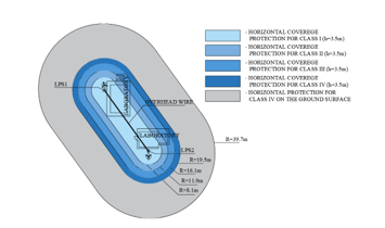 Figure 30: Horizontal projection screen of an LPS project (only for guidance)
9.2. Control of the total number of people in the Zones
When the number of people distributed in all Zones is inserted, the System verifies consistency. So, in case of divergence with the total number reported in the Registry (Figure 4), it issues an alert and blocks for further correction, either for more (Figure 32) or for less (Figure 33):
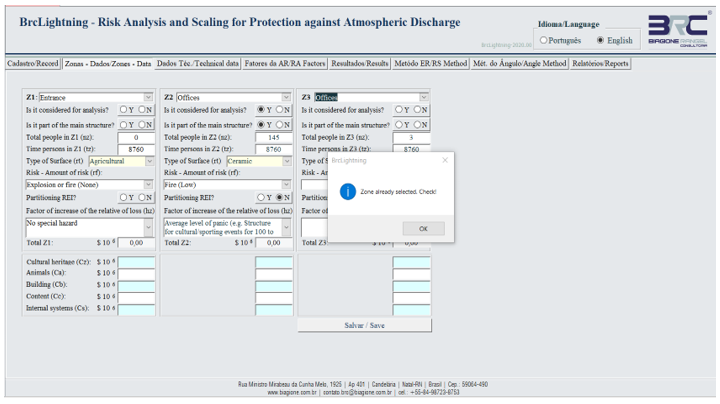 Figure 31: Zone alert already selected
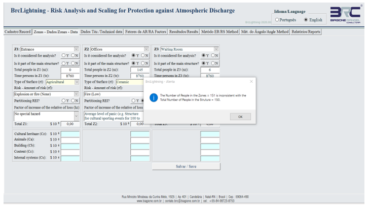 Figure 32: Alert of more people in the Zones than the registered total
 Figure 33: Alert of fewer people in the Zones than the total registered
9.3. Consistencies of line parameters
The System filters the options of values of the probability PLD depending on the resistance RS of the cable screen and the impulse withstand voltage UW of the equipment, based on the line type, routing, shielding, and bonding conditions, as can be seen in Figure 34. Power line is not bonded to the same bonding bar as equipment and telecom is bonded to the same bonding bar as equipment.
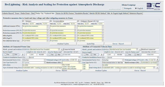 Figure 34: Filters for line parameters
9.4. Restrictions for changing typical loss values
When it comes to loss of human life (L1), the typical LT loss values (loss due to injuries from electric shock) cannot be changed (the system freezes). The same applies to the typical LF loss value (loss in a structure due to physical damage) when it is indicated that there is a risk of explosion in the Zone or when it is indicated that the place is a hospital, hotel, school or civic building.
In addition, changes in typical LO loss values (loss in a structure due to failure of internal systems) are blocked when it comes to areas that are part of the hospital or life support structure. When dealing with L2 and L3 losses, the values of LF and LO are also blocked for changes. For losses of type L4, permissions similar to L1 losses are applied. Blocking alerts are via a pop-up message, as shown in Figure 35.
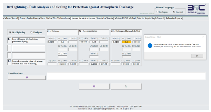 Figure 35: Blocking alert screen for changing typical loss value
9.5. Permission to modify data and customize
It is important to emphasize that to perform any customization and or modify parameters predefined in the System, there is a need for the professional to make, in advance, his or her registration in the system and, after that, he or she will have to define on the initial screen (Figure 4) the designer responsible for the project. This way, the system will save the modifications in an associated way with the person responsible for performing them.
10. Acknowledgment
This is a work that I have been developing alone, from the need I had to carry out the evaluation of projects of Protection Against Atmospheric Discrimination. Therefore, to be certain about my work, I developed the methodology and then the migration to the programming codes of this system, having paid every expense with my own resources, including all the development so far and the costs regarding my participation in all the previous symposia and the development of the papers.
11. Conclusion
This paper is in line with the conclusion of the work originally presented at the SIPDA XV symposium [1], as it incorporates new resources to provide LPS designers with more efficient and safe tools and means for project development, in accordance with Brazilian, International and American standards.
In this context, the BrcLightning application continues, also, with the objective of consolidating itself as an integrated software, having as a support, for some of its modules, the dimensioning of LPS based on the mathematical approach, which was developed and presented at the SIPDA XIII [9] and SIPDA XIV [10] symposia. Thereby, we hope to be contributing to a better understanding of the standards and to the development of safer and more effective projects for protection against lightning strikes.
Also, its modulated design and the format of a database allows the development of applications to be used on the internet, online, and by app systems used on cell phones or other mobile devices.
- Araujo, Biagione R, “ BrcLightning – Risk Analysis and Scaling for Protection against Atmospheric Discharge,” International Symposium on Lightning Protection (XV SIPDA), vol. 1, nº 0, p. 8, 2019.
- ABNT, “NBR-5419-2. Lightning protection Part 2: Risk management,” ABNTCatálogo, p. 116, 2015.
- IEC, “IEC 62305-2. Protection against lightning – Part 2: Risk management,” IEC, 2012.
- ABNT, “NBR-5419-3. Lightning protection – Part 3: Physical damage to structures and life hazard,” ABNTCatálogo, 2015.
- IEC, “IEC 62305-3 – Protection against lightning – Part 3: Physical damage to structures and life hazard,” IEC, 2012.
- NFPA, “ NFPA 780. Standard for the Installation of Lightning Protection Systems. s.l. : IHS,” NFPA, 2014.
- ABNT, “NBR-5419-4. Lightning protection – Part 4: Electrical and electronic systems within structures. n.l.,” ABNTCatálogo, 2015.
- IEC, “IEC 62305-4 – Protection against lightning – Part 4: Electrical and electronic systems within structures. n.l. : IEC,,” IEC, 2010.
- Araujo, Biagione R, Oliveira Jose T. , “Mathematical Approach Methodology to Analysis and Design of LPS,” International Symposium on Lightning Protection (XIII SIPDA), 2015.
- Araujo, Biagione R, “Mathematical Modeling for Analysis and Design of LPS Angle Method,” International Symposium on Lightning Protection (SIPDA XIV), 2017.