Robust Adaptive Feedforward Sliding Mode Current Controller for Fast-Scale Dynamics of Switching Multicellular Power Converter

Adv. Sci. Technol. Eng. Syst. J. 6(1), 1304–1311 (2021);
 DOI: 10.25046/aj0601149
Higher efficiency and lower losses are widely considered as the best metrics to optimize, in a high-power converter performance context. To provide a solution to the ever-increase of high switching frequencies challenges, we must explore soft-switching technologies to resolve interface issues and reduce the switching losses. This manuscript describes a comparative analysis between the fixed-bandwidth (FBW) and the variable-bandwidth (VBW) of the hysteresis modulation (HM) based on the conventional sliding mode (CSM) strategy. The two adopted techniques are applied to a bidirectional multichannel DC-DC asynchronous Buck converter. The cells are parallel-connected and operating in continuous conduction mode (CCM). The objective is to have a system that is more stable, more efficient and able to cope with variations in input voltage, load and desired output voltage. That requires, first, to attenuate the non-linearity phenomenon of the conventional sliding mode by placing a hysteresis modulation. Then, after applying this technique, we confronted the dilemma of the variable switching frequency. Our hypothesis was to incorporate a variable bandwidth of the hysteresis modulation. The results obtained under parametric variation clearly show the areas where significant differences have been found between the two approaches. Likewise, they both share several key features. Simulation studies in the MATLAB® / Simulink™ environment are performed to analyze system performance and assess its robustness and stability.
1.Introduction
DC-DC converters, with many different topologies, represent a hotspot in modern technology and have revolutionized switching control. Although the characteristics of power electronics, in terms of nominal voltage and current values, continue to improve, the range of applications continues to expand in several areas including energy storage, automation, transport, high power industrial drives and transmission / distribution of electrical energy [1], [2]. Whereas the needs for higher efficiency, reliability, modularity in high electronics power, multicellular converters are on the rise. Studies [3–6] based on a parallel multiphase topology have shown that the latter provides better performance, lower losses, reduced cost, and fast dynamic responses. Parallel-connected multi-cell DC-DC converters have an important role in several applications such as inverters, powertrain systems and equipment of the power factor correction and they have countless advantages, the major one is to enhance performances such as energy efficiency and high capacity [7–11]. One approach dedicated to small converters is to run them at a higher switching frequency, this will reduce the size of reactive components (inductors and capacitors) and it contributes to the improvement of the output voltage’s quality of the converter. High losses in the IGBT switches remains the major limitation of the high frequencies, which reduces efficiency. Significant information and in-depth investigations in the same framework can be found in these studies [12–18].
Higher efficiency and more stringent control features of power electronics become very attractive. Nonlinear Sliding mode controllers applied to parallel multi-cell converters combine control concepts with multiple sliding surfaces and integral variable structure. They are easy to design, robust and shows good transient and stable performances. Furthermore, they restrict the switching frequency variation, mitigate the undesired transient response and achieve a good compromise between transient and stationary performances. Hence, there are two ways of control involved for multicellular converters. The first consists in controlling the multi-commutations with phase shifting from one another, one therefore speaks of interleaving. The second is to apply the same control signal simultaneously to the multi-switchings, it is therefore synchronicity. The controllers developed for paralleled multiphase converters take into consideration most of the characteristics mentioned above [19]. To date, several researchers have reported that these control schemes have many desirable features: easy-designed because each sliding surface is independently controlled, smooth transient responses tested under parametric variations, eliminate the problem of chattering, the impact of high switching frequencies is managed by the integrators. All these promising results have been experimentally proven on a closed loop system. Previous studies proposed to use the extended linearization method for the design of the sliding mode controller, and then improving robustness using the combined controllers. Thus, they developed a procedure to choose the high-pass filter parameters of the sliding mode-controlled converters. In addition, they presented derivatives of sliding mode control, including the direct /indirect sliding mode, the integral sliding mode, the proportional sliding mode and the high order sliding mode [20–28]. As far, sliding mode control has been widely studied and has proven to be a future solution for generations of power converters, yet, it suffers from the problem of high frequency oscillation (chattering) due to the practical limitations of system components and the problem of switching frequency variation by applying the traditional sliding mode.
This leads us to propose an implementation of the sliding mode controller by hysteresis function. The implementation is easy to reproduce and does not require additional auxiliary circuits or complex calculations. The introduction of a hysteresis band as the limit conditions of the sliding mode, delays the period of states exchange and gives a sign to control the switching frequency of the system, and therefore, the trajectory of the system variates in close proximity to the excesses of the band. So, the practical problem of chattering will be solved. Particularly, boundary layer-based control schemes allow multicell converters to operate with a fixed switching frequency [29–35]. This strategy will be fully covered in the rest of our work. The remainder of the paper is organized as demonstrated: In Section II, the adopted system is described and modeled. Section III reviews the control mechanism based on the sliding mode controller. Section IV is devoted to analyze the simulation results and to discuss the effectiveness of the control strategies. The conclusion is reported in Section V.
2. Paralleled Non-Isolated Multi-Cell Converter
The studied three-cell DC-DC buck converter is shown in Figure 1. It consists of a constant DC input voltage source Vin connected to three similar modules sharing a resistive load R and a filter capacitor C. Each module is based on an implemented controllable power MOSFETs S, the antiparallel diode D that authorizes the embedded switch to exhibit a bidirectional current conduction property and a filter inductor L. Note that the parallel switching buck converter operates in continuous conduction mode (CCM). The three cells are identical, in other words, L1=L2=L3.
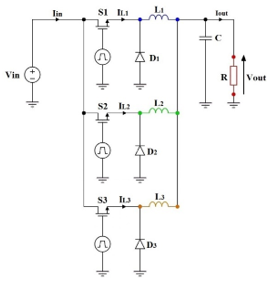 Figure 1: Three-channel Buck converter parallel-associated
The converter can be represented by a system of equations based on a model with mean values, then the system dynamics of the studied converter can be expressed as:
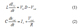 Where ILj is the current flowing through inductance j = 1,2,3, IL the current at the output of the converter, Vin is the input voltage and Vout is the output voltage of our converter and Vref is the desired output voltage. The state of space can be expressed as:
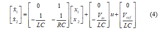
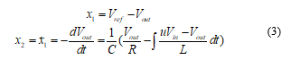 This model can be used directly to simulate the converter, in MATLAB / Simulink type environment.
3. Hysteresis Modulation-Based Sliding Mode Controller
We propose two different control schemes, developed in the continuous domain, to stabilize parallel multi-phase standalone converter and compare them. The proposed sliding mode control (SMC) strategy based on hysteresis modulation (HM) automatically compensates for the parametric variations of the converter and the variation of the line impedance, such that it allows the three-cell paralleled converter to share the load and does not require the modules to be interconnected. We illustrate the fixed-bandwidth of the hysteresis modulation technique-based sliding mode control; however, this approach has accentuated the problem of variable switching frequencies that requires a high-bandwidth current sensor. At this point in our work, we are interested in an adaptive and feedforward current control solution to overcome this problem and adapt a variable-bandwidth of the hysteresis modulation to mitigate the nonlinearity phenomenon in conventional sliding mode control to fix the switching frequency.
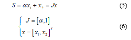
Describing the mathematical model of the system in question, operating in CCM, and especially its states of space necessary for the design of the sliding mode voltage control (SMV), the reformed expression of the state of space is:
 Employing the sliding mode voltage control (SMVC) and taking into account the state trajectory that includes the control parameters x1 and x2, we can determine the switching function u.
 That forms the control law:
![]() The convergence conditions are the criteria that allow the dynamic errors of the system to converge towards the sliding surface. They are ensured by a judicious choice of the function of LYAPUNOV, which guarantees the attraction of variables to regulate to their references, to build the discontinuous control size and meet the stability criterion:
The convergence conditions are the criteria that allow the dynamic errors of the system to converge towards the sliding surface. They are ensured by a judicious choice of the function of LYAPUNOV, which guarantees the attraction of variables to regulate to their references, to build the discontinuous control size and meet the stability criterion:
![]() Thus, the existence condition for the adopted control strategy is:
Thus, the existence condition for the adopted control strategy is:
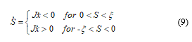
where ξ is a positive quantity, infinitely small and arbitrarily chosen.
Substituting (3) and (5), we find:
![]() The sliding coefficient is set as (11) and thus the above equation is valid:
The sliding coefficient is set as (11) and thus the above equation is valid:
![]() We can therefore deduce the conditions of existence:
We can therefore deduce the conditions of existence:
 The bandwidth of the FBW regulator based sliding mode controller has been selected according to the following equation:
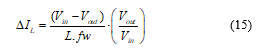
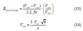 Hence, we focus on the adaptive feedforward current control technique in continuous conduction mode (CCM). So that, the expression of the current variation ∆IL, as a function of the input voltage Vin, the output voltage Vout, the switching frequency fw, and the value of the inductance L, can be shown as:
 Still with the aim of ensuring the operation at fixed frequency of the proposed hysteresis modulator, a requirement is imposed, and that the hysteresis bandwidth must satisfy it, is:
![]() The dynamic performance of the two schemes needs to be demonstrated under conditions when some changes are imposed and a feedforward transient occurs. Simulations are performed for various cases of the circuit parameter variations: load changes, input voltage changes and reference voltage changes.
The dynamic performance of the two schemes needs to be demonstrated under conditions when some changes are imposed and a feedforward transient occurs. Simulations are performed for various cases of the circuit parameter variations: load changes, input voltage changes and reference voltage changes.
4. Simulation Results and Robustness Assessment
In this part, and to properly study the behavior and performance evaluation of the closed-loop converter and the various control techniques synthesized in the previous section, particularly when modifying the operating conditions, we will simulate the behavior of a 3-cell chopper connected to an R load. A robustness test was carried out to analyze the sensitivity of the strategies and the correctors implemented with regard to possible variations in the parameters of the model. For the parameter’s identification of the studied converter, we determine the nominal values of the inductance L and the capacitance C using the conditions below:
- The current through the inductance, must be within a reasonable interval, for all the conditions of charge, because our converter is operating in continuous conduction mode.
- The maximum ripple of the output voltage should not exceed a small percentage, usually 5% of the output voltage Vout.
Taking these conditions into account, the LC filter must obey the conditions of the relationships below, where fw corresponds to the switching frequency and β is the duty cycle.

![]() Table 1 shows the specifications that we adopted of the studied buck converter simulated in the MATLAB® environment.
Table 1 shows the specifications that we adopted of the studied buck converter simulated in the MATLAB® environment.
Table 1: Specifications of The Paralleled Three-Channel Buck Converter
| Description | Parameters | Nominal Value |
| Input voltage | Vin | 24 V |
| Capacitance | C | 60 µF |
| Inductance | L | 50 mH |
| Resistance | R | 12 Ω |
| Switching frequency | fw | 400 kHz |
| Desired output voltage | Vref | 12 V |
Figure 2 duplicates the variation of the average switching frequency as a function of the input voltage variation. The VBW HM-based SMC adaptive feedforward control reduces switching frequency variation compared to the FBW HM-based SMC control. This result highlights the major contribution of our work, thanks to the developed strategy, we achieve a significant reduction in the variation of the switching frequency.
Figure 3 and Figure 4 show the output voltage response for the two control strategies used. it seems clear that the system operating with VBW HM-based SMC achieves the best compromise passing from the transient regime to the stationary regime. Thus, its transition response is smoother, more stable, without overshoot and with less chatter, on the other hand, the response of our system under the control of the FBW HM-based SMC is faster but it represents more variation in amplitude of the oscillations, with an overshoot.
It appears clearly from Figure 5 and Figure 6, during an increase/decrease in resistance (50% variation) every 0.2s, that the closed-loop output voltage response reacting with the FBW HM-based SM exhibit an undesired transient drop that lasts a few seconds and disturbs the smoothness of the output voltage followed abruptly by a steady-state. While, in the other case, the system compensates for a transient drop in a soft way. Through the output current simulation results, we can observe that the VBW HM-based SM goes perfectly with the load changes to even almost assure that there is no transient regime. Figure 7 and Figure 8 point-out the output voltage response and the output load current response for the two controllers when the system undergoes a change in the input supply (Vin varied from 24V to 50V) at 0.2s. For the two cases, the chattering increase, however, the output voltage and the output load current vary around the reference values. The zoom in clearly shows an increase in the amplitude of the oscillations accompanied by an upward shift of the output voltage in steady-state regime when the input voltage increases, it comes down to the variation of the switching frequency.
Figure 9, Figure 10, Figure 11 and Figure 12 present the output voltage response and the output load current response for the two controllers when the system undergoes a change in the output reference (Vref varied from 12V to 20V). Switching from one value to another is almost similar, there is no big difference except that the VBW HM-based SM is more precise. The carried-out simulations show extremely encouraging outcomes as far as reference tracking effectiveness and robustness, a quick estimation of the control law permits a quicker dismissal of the unsure load impact. They demonstrate the propriety of sliding mode control for such sort of framework.
The results in terms of stability assessment and performance analysis under system parameters variation are recapitulated in Table 2.
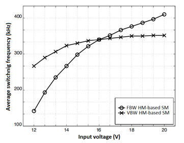 Figure 2: The variation of the average switching frequency as a function of the input voltage variation.
Table 2: Comparative Performances of FBW HM-SMC with VBW HM-SMC
| FBW HM-based SMC | VBW HM-based SMC | ||
| Load variation | |||
| Time of compensation | 0.01 s | 0.015 s | |
| The drop width | 0.22 V | 0.13 V | |
| Amplitude of oscillations | ±0.15 V | ±0.1 V | |
| Response time | 0.02 s | 0.03 s | |
| Input variation | |||
| Amplitude of oscillations | |||
| For | ±0.14 V | ±0.12 V | |
| For | +0.3 V
-0.15 V |
±0.12 V | |
| Reference variation | |||
| Time of transition | 0.015 s | 0.03 s | |
| Amplitude of oscillations | ±0.14 V | ±0.12 V | |
 Figure 3: (a) The Output voltage response for the FBW HM-based SMC. (b) Zoom in
 Figure 4: (a) The Output voltage response for the VBW HM-based SMC. (b) Zoom in
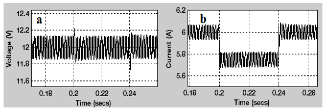 Figure 5: (a) The output voltage response. (b) The output load current response.
Both for the FBW HM-based SMC when the system undergoes a slight change in the load resistance.
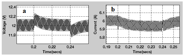 Figure 6: (a) The output voltage response. (b) The output load current response.
Both for the VBW HM-based SMC when the system undergoes a slight change in the load resistance.
 Figure 7: (a) The output voltage response. (b) The output load current response.
Both for the FBW HM-based SMC when the system undergoes a change in the input supply.
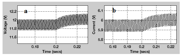 Figure 8: (a) The output voltage response. (b) The output load current response.
Both for the VBW HM-based SMC when the system undergoes a change in the input supply.
 Figure 9: (a) The output voltage response for the FBW HM-based SMC when the system undergoes a change in the output reference.
(b) Zoom in.
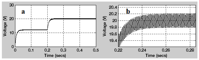 Figure 10: (a) The output voltage response for the VBW HM-based SMC when the system undergoes a change in the output reference.
(b) Zoom in.
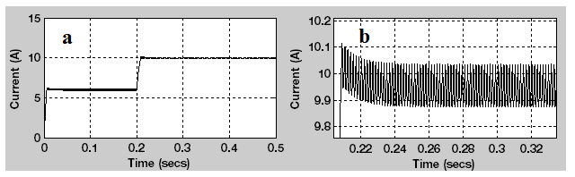 Figure 11: (a) The output load current response for the FBW HM-based SMC when the system undergoes a change in the output reference.
(b) Zoom in.
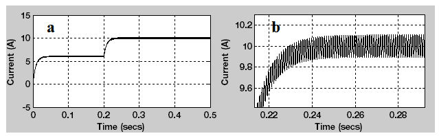 Figure 12: (a) The output load current response for the VBW HM-based SMC when the system undergoes a change in output reference.
(b) Zoom in
5. Conclusion
The variable-bandwidth hysteresis modulation is favored because it ensures the chattering suppression caused by the switching of the MOSFETs and provides high efficiency since it offers a greatly desired output voltage tracking. The VBW HM-based SMC is faster to the point that the response time at 5% is mostly short. His appropriate dynamic accuracy is characterized by zero overshoot during the transient regime for the output voltage response, contrariwise to the FBW HM-based SMC that represents 2.5% overshoot. The output voltage regulation is improved from 2% (Vin=24V) to 0.15% (Vin=24V) through the VBW HM-based SMC. Add to that, the frequency variation is reduced from 30% to 15% with the developed strategy. The various control techniques provide similar performances, they have improved the dynamic conduct and they can adapt to include voltage and load varieties. The use of variable bandwidth hysteresis modulation and fixing of the switching frequency leads to large scale dynamics.
- R. Hamdi, A.H. Hamida, O. Bennis, F. Babaa, “HM-Based SMVC with Adaptive Feedforward Controller Applied to DC-DC Converter,” International Conference on Electrical and Information Technologies (ICEIT), IEEE: 1–6, 2020, doi:10.1109/ICEIT48248.2020.9113220.
- Li W, He X, “Review of nonisolated high-step-up DC/DC converters in photovoltaic grid-connected applications,” IEEE Trans Ind Electron, 58:1239–50, 2011. doi:10.1109/TIE.2010.2049715.
- W. Do, K. Eguchi, A. Shibata, “An analytical approach for parallel switched capacitor converter,” Energy Reports, 6, 338–342, 2020, doi:10.1016/j.egyr.2020.11.233.
- M. Srinivasan, A. Kwasinski, “Control analysis of parallel DC-DC converters in a DC microgrid with constant power loads,” International Journal of Electrical Power and Energy Systems, 122, 106-207, 2020, doi:10.1016/j.ijepes.2020.106207.
- H. Li, X. Jiang, Y. Zou, C. Liu, “A time-domain stability analysis method for paralleled LLC resonant converter system based on Floquet theory,” Microelectronics Reliability, 114, 113-849, 2020, doi:10.1016/j.microrel.2020.113849.
- MSB. Ranjana, N. Sreeramulareddy, RKP. Kumar, “A novel nonisolated switched inductor floating output DC-DC multilevel boost converter for fuelcell applications,” Conference on Electrical, Electronics and Computer Science, 2014, doi:10.1109/SCEECS.2014.6804492.
- M. Sagar, B. Ranjana, “A Novel Non-Isolated Switched Inductor Floating Output DC-DC Multilevel Boost Converter For Fuelcell Applications”, 2014, doi:10.1109/SCEECS.2014.6804492.
- S. Ben Said, K. Ben Saad, M. Benrejeb, “ScienceDirect HIL simulation approach for a multicellular converter controlled by sliding mode,” International Journal of Hydrogen Energy, 1–7, 2017, doi:10.1016/j.ijhydene.2017.01.198.
- P. Djondiné, “Overview of Control Techniques for Multicellular Converter,” Journal of Engineering Sciences, 5(1), 10–14, 2018, doi:10.21272/jes.2018.5(1).e3.
- P. Taylor, M. Defoort, M. Djemai, T. Floquet, W. Perruquetti, “Robust finite time observer design for multicellular converters,” International Journal of Systems Science Robust finite time observer design for multicellular converters”, 37–41, 2011, doi:10.1080/00207721.2010.543494.
- F. Engelkemeir, A. Gattozzi, G. Hallock, R. Hebner, “Electrical Power and Energy Systems An improved topology for high power softswitched power converters,” Electrical Power and Energy Systems, 104, 575–582, 2019, doi:10.1016/j.ijepes.2018.07.049.
- S. Ogasawara, H. Akagi, A. Nabae, “A novel PWM scheme of voltage source inverters based on space vector theory,” Arch Für Elektrotechnik, 74, 33-41, doi:10.1007/BF01573229.
- N. Patin, “Power Electronics Applied to Industrial Systems and Transports,” 2016, doi:10.1016/C2015-0-04476-8.
- O. Hegazy, J. Van Mierlo, P. Lataire, “Analysis , Modeling , and Implementation of a Multidevice Interleaved DC / DC Converter for Fuel Cell Hybrid Electric Vehicles,” 27(11), 4445–4458, 2012.
- NH. Baharudin, TMNT. Mansur, FA. Hamid, R. Ali, MI. Misrun, “Performance Analysis of DC-DC Buck Converter for Renewable Energy Application,” J. Phys. Conf. Ser., 1019, Institute of Physics Publishing, doi:10.1088/1742-6596/1019/1/012020.
- A. Kolli, A. Gaillard, A. De Bernardinis, O. Bethoux, D. Hissel, “A review on DC / DC converter architectures for power fuel cell applications,” Energy Conversion And Management, 105, 716–730, 2015, doi:10.1016/j.enconman.2015.07.060.
- D. Boroyevich, H. Vanlandingham, W.T. Baumann, “Nonlinear Analysis and Control of Standalone , Parallel DC-DC , and Parallel Multi-Phase PWM Converters,” 2001.
- M. Andrade, V. Costa, “DC-DC Buck Converter with Reduced Impact,” Procedia Technol, 17, 791-8, 2014, doi:10.1016/j.protcy.2014.10.209.
- KVR. Swathi, GVN. Kumar, “Design of intelligent controller for reduction of chattering phenomenon in robotic arm: A rapid prototyping,” R. Comput Electr Eng,1-15, 2017, doi:10.1016/j.compeleceng.2017.12.010.
- M. Alfayyoumi, AH. Nayfeh, D. Borojevic, “Modeling and analysis of switching-mode DC-DC regulators,” Int J Bifurcat Chao, 10, 373-90, 2000, doi:10.1142/S0218127400000244.
- H. Al-Baidhani and al., “Sliding-Mode Voltage Control of Dynamic Power Supply for CCM,” IEEE International Symposium on Circuits and Systems (ISCAS), 1-5, 2019, doi:10.1109/ISCAS.2019.8702628.
- Y. Wu, Y. Huangfu, R. Ma, A. Ravey, D. Chrenko, “A strong robust DC-DC converter of all-digital high-order sliding mode control for fuel cell power applications,” Journal of Power Sources, 413, 222–232, 2019, doi:10.1016/j.jpowsour.2018.12.049.
- S. Das, M. Salim Qureshi, P. Swarnkar, “Design of integral sliding mode control for DC-DC converters,” in Materials Today: Proceedings, Elsevier Ltd: 4290–4298, 2018, doi:10.1016/j.matpr.2017.11.694.
- S.K. Pandey, S.L. Patil, D. Ginoya, U.M. Chaskar, S.B. Phadke, “Robust control of mismatched buck DC–DC converters by PWM-based sliding mode control schemes,” Control Engineering Practice, 84, 183–193, 2019, doi:10.1016/j.conengprac.2018.11.010.
- Y. Gao, J. Liu, G. Sun, M. Liu, L. Wu, “Systems & Control Letters Fault deviation estimation and integral sliding mode control design for Lipschitz nonlinear systems,” Systems & Control Letters, 123, 8–15, 2019, doi:10.1016/j.sysconle.2018.08.006.
- S.K. Pandey, SL. Patil, D. Ginoya, UM. Chaskar, SB. Phadke, “Control Engineering Practice Robust control of mismatched buck DC – DC converters by PWM-based sliding mode control schemes,” Control Engineering Practice, 84, 183–193, 2019, doi:10.1016/j.conengprac.2018.11.010.
- B.B. Naik, AJ. Mehta, “Sliding mode controller with modi fi ed sliding function for DC-DC Buck Converter,” ISA Transactions, 2017, doi:10.1016/j.isatra.2017.05.009.
- A. Fezzani, S. Drid, A. Makouf, “Commande Robuste par Mode Glissant d ’ Ordre Supérieur de la Machine Synchrone à Aimant Permanent,” 247–251, 2010. http://eprints.univ-batna2.dz/1230/.
- M.S. Shaker, AA. Kraidi, “Robust observer-based DC-DC converter control u,” Journal of King Saud University – Engineering Sciences, 2017, doi:10.1016/j.jksues.2017.08.002.
- K.V.R. Swathi, GVN. Kumar, “Design of intelligent controller for reduction of chattering phenomenon in robotic arm: A rapid prototyping R,” Computers and Electrical Engineering, 1–15, 2017, doi:10.1016/j.compeleceng.2017.12.010.
- M. Phattanasak, W. Kaewmanee, J. Martin, S. Pierfederici, B. Davat, “Interleaved Double Dual Boost Converter for Renewable Energy System,” 932, 904–909, 2014, doi:10.4028/www.scientific.net/AMR.931-932.904.
- R. Ramos, D. Biel, E. Fossas, R. Grin, “Control Engineering Practice Sliding mode controlled multiphase buck converter with interleaving and current equalization,” 21, 737–746, 2013, doi:10.1016/j.conengprac.2012.09.005.
- A. El Aroudi, R. Giral, J. Calvente, “Sliding-Mode Control of DC-DC Switching Converters,” IFAC, 2011, doi:10.3182/20110828-6-IT1002.00557.
- A. Mehta, B. Naik, “Sliding Mode Controller with PI-Type Sliding Function for DC–DC Buck Converter,” In: Sliding Mode Controllers for Power Electronic Converters. Lecture Notes in Electrical Engineering, vol 534, Springer, doi:10.1007/978-981-13-3152- 7_3.
- F. Blaabjerg. “Control of Power Electronic Converters and Systems,” Elsevier 2018, ISBN:978-0-12-816136-4, doi:10.1016/c2017-0-04756-0.