Downlink Indoor Coverage Performance of Unmanned Aerial Vehicle LTE Base Stations
 , Kerem C ̧ agdas ̧ Durmus ̧, Gülçín Tanıs ̧, Caner Arslan, Metin Balcı
Adv. Sci. Technol. Eng. Syst. J. 6(1), 128–133 (2021);
 DOI: 10.25046/aj060114
In this study, we study on the downlink indoor coverage performance of unmanned air vehicle (UAV) base stations. We consider a probabilistic expression for air-to-ground (ATG) path loss, and a deterministic one for additional indoor losses in order to provide a practical model. One of our important assumptions is that the UAV base station operates at the frequencies reserved for 4th Generation (4G) – Long Term Evaluation (LTE) based mission critical services in Turkey–around 2.6 GHz–. Therefore, we are able to neglect intercell interference issue, and we may rely on signal-to-noise ratio (SNR) for our coverage definition. We consider four different SNR requirement throughout our performance evaluation, and investigate the effect of UAV altitude and other related parameters on the radius of service area. We first observe that rural coverage performance is always better than urban conditions –this result is fully compatible with the fact that attenuation levels significantly arise in urban regions–. In addition, we show that increasing quality of service (QoS) requirement and/or using a more directive antenna unit decrease the coverage radius as they are expected. Thereupon, we conclude that it is possible to obtain the optimum altitude level –by employing the framework proposed here– in order to satisfy certain service criteria.
1. Introduction
In this paper, we extend one of our earlier studies presented in 27th Signal Processing and Communications Applications Conference (SIU) [1]. As we argue in [1], UAV base station idea seems to be a promising solution to provide cellular service for both the locations which cannot be covered by employing terrestrial networks and the times in which terrestrial networks may not be serving at all (e.g. natural disasters). In [2] and [3], earlier studies related to the UAV base station concept are summarized, and possible use cases are investigated. In addition, topics open for further studies are discussed in these publications as well. Among several other topics to discuss, modelling channel conditions of such a non-terrestrial network in a practical and also tractable way is an important requirement [4]–[11].
In [4, 5, 6], coverage performance of UAV networks is investigated for outdoor users, and the effect of UAV altitude on the coverage radius is discussed in detail. In the studies mentioned, ATG channel is modelled in two parts. First part corresponds to the free-space losses, and assumed to be a deterministic function which depends on the radiation distance. Second part basically aims the losses in where man-made structures exist –urban environment–, and modelled as a Normal distributed random variable. In this paper, we follow this piecewise model to express the path loss related to ATG channel, and examine urban and rural conditions separately. The reason of the using deterministic approaches is that reliable characterization of the ATG propagation for large scale fading statistics. In addition, it is important to note that fast fading effect of the channel is ignored throughout this study.
Some earlier publications related to the topic utilize a practical UAV to form a testbed, and generate empirical channel models to figure out ATG propagation characteristics [9]–[11]. All three of those are funded by the same institution, and aims to model overwater, mountainous and near-urban environments, respectively. As the next step of this work, we also target to assemble a functional and realistic testbed.
Besides, some previous studies utilize stochastic processes to concentrate on outdoor coverage performance of UAV base stations [12, 13]. Authors of the former assume that both UAV and terrestrial base stations are deployed in an overlapping manner, and coordinate with each other to provide a continuous service. Such an overlapping structure of UAV and terrestrial base stations is not covered in the scope of this paper. The latter one considers only UAV base stations distributed according to a Poisson point process (PPP). Then, authors provide approximate expressions for both coverage ratio and average data rate. Here, we emphasize that we assume there exists only one UAV base station that operates on mission critical frequency bands, and therefore such stochastic processes are not required to model UAV base station density around. Yet, as a future concern, investigating networks consist of multiple UAV base stations is already scheduled.
Another significant aspect of this work is considering additional losses to serve indoor users. In literature, these indoor losses are generally studied for terrestrial networks rather than UAV ones [14]– [17]. In [14, 15], indoor losses are evaluated as a function of number of floors penetrated. Authors of [16, 17] offer a more complicated system model which accounts the number of internal/external walls and indoor propagation distance. Since only the latter one of these supports sub-6 GHz frequency bands, we follow the model proposed in [17]. Once we build a practical testbed, generating a novel indoor propagation model will be another important objective in our agenda.
Rest of this paper is organized as follows: Section 2 summarizes the system model that we employ, Section 3 proposes a parametric expression for indoor coverage ratio, Section 4 calculates coverage radius for several SNR demands, quality-of-service (QoS) requirements and antenna directivity levels, and finally Section 5 discusses the results obtained throughout our extensive simulations.
2. System Model
The aim of this study is to show that UAV base stations can be provide a fast and effective coverage in areas not covered by terrestrial networks or in emergency situations –by using frequency bands reserved for mission critical services–. Considering that UAV base station users are not exposed to interference, SNR is employed as performance criterion. The altitude range of UAV base station is accepted as 0.5-3 km. Maximum velocity of the UAV is 180 km/h. The movement of the UAV can be neglected because displacement on the air within the channel stationarity duration is too small compared to altitude of the UAV. Figure 1 shows an example of UAV base station layout.
The study assumes that UAV carries an outdoor base station which operates on Band 7 (2.6 GHz) which is defined by European Telecommunications Standards Institute (ETSI) as an LTE frequency band [18]. In this system model, UAV base station works on Single Input Single Output (SISO) mode and has single sector which is 120◦.
2.1 Propagation Model and Antenna Gain
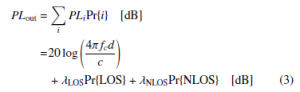
In the literature, the propagation model of UAV base stations is examined in two parts as free space loss and urban losses [5]. It is accepted that free space loss has a deterministic character and urban losses have a probabilistic one. The attenuation for cases with line of sight (LOS) and non line of sight (NLOS) are as follows:

where fc, d, c and λi, i ∈ {LOS,NLOS} refers to carrier frequency, propagation distance, speed of light and urban losses respectively. In literature, these urban losses are considered to have a Normal distribution: λLOS ∼ N(µLOS,σ2LOS) and λNLOS ∼ N(µNLOS,σ2NLOS). µi and σ2i , i ∈ {LOS,NLOS} express the mean and variance values of corresponding Normal distributions and numerical values can be calculated with respect to the propagation angle.

Figure 1: UAV base station coverage region.
The LOS and NLOS possibilities required to complete the propagation model are also functions of the propagation angle and denoted as follows:

Since calculating the constants a and b above is not in the scope of this study, numerical values are given in Chapter 4. The average loss of external environment obtained using Equations (1) and (2) can be expressed as follows:
In addition, a model defined by ETSI is used to evaluate base station antenna gain [19]. According to this model, the antenna gain is given as a function of the beam angle:
![]()
where α3dB, is the beam width corresponding to a 3 dB loss and its value basically determines the directivity of the antenna. Also, Gmax = 15 dB and Amax = 20 dB represent the maximum antenna gain and the maximum attenuation, respectively. Variable of the expression above, namely beam angle is indeed a function of penetration angle: α = π/2 − θ.
2.2 Indoor Model
In literature, there exist studies which expresses indoor penetration {internal and external walls) and free space loss due to the indoor propagation by using empirical models [16, 17]. Within the model given in [17], total path loss for indoor users is given as follows:
![]()
where din and m denote the indoor propagation distance and the indoor path loss constant. n, Lin, k and Lout represent the number of penetrated internal walls, penetration loss of one internal wall, number of external walls penetrated and penetration loss of one external wall, respectively. The values of these parameters at the carrier frequency of 2.6 GHz are given as m = 0.49 [dB/m], Lin = 4.9 [db] and Lout = 24.8 [dB]. In this study, it was assumed that one external and one inner wall is penetrated to provide indoor coverage, and there is an indoor propagation distance of five meters. Therefore, the additional loss due to indoor coverage is calculated as PLin = 32.15 dB.
2.3 Performance Criterion
As it is stated above, we assume that UAV base station utilizes the frequencies reserved for mission critical services. Thereby, we do not consider any interference effect, and employ SNR as our performance criterion. More precisely, we define the coverage incident by the probability of SNR is greater than a given threshold. By using (3), (4) and (5), SNR can be calculated as follows:
![]()
Here, Ptx ve PN represent transmitted signal strength and noise power, respectively. We note that total noise power is basically given as a function of bandwidth (BW). In the following section, by using the system model given, the probability of indoor coverage of ATG communication systems will be expressed.
3. Probability of Indoor Coverage
Indoor coverage probability of a geographical location is defined as the probability of SNR exceeds a certain value. Corresponding expression is given as

where s ∈ {0.76,4.7,10.4,15.9} refer to the different SNR limits considered in this study. The reason for choosing values given is that these values are used in the literature as SNR levels to determine certain channel quality indices (CQIs) [20].
As given in (3), PLout is basically the summation of the two different random variables with Normal distribution multiplied by two coefficients, namely Pr{LOS} and Pr{NLOS}. Thereupon, we conclude that PLout is also a Normally distributed random variable

where µPL and σ2PL represent the mean and variance parameters of the distribution, respectively. Numerical values of mean and variance can be calculated as follows:
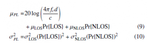
Once we compute the distribution parameters in (9) and (10) –and according to the fact that outdoor path loss is modelled as a Gaussian random variable–, coverage probability given in (7) can be evaluated by using the tail probability which is defined as Q function [21]. Thus, (7) is given as
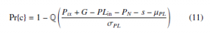
As a result of Q function exists in (11), it is not easy to express coverage probability in closed form. Yet, a fast, numerical solution exists. In the next section, we demonstrate our comprehensive simulation results in order to support our theoretical findings.
4. Numerical Analysis
In this section, we investigate the coverage radius for different SNR demands by utilizing the coverage expression above. The system parameters used in the simulations are: fc = 2.6 GHz, Ptx = 46 dBm, α3dB = 65◦, BW = 10 MHz, PN = −95 dB, arural = 4.88,
aurban = 9.61, brural = 0.43 and burban = 0.16. The center frequency and bandwidth of the base station are commonly used numerical values in LTE systems. Transmit power is maximum base station power value for given bandwidth standardised by ETSI [19]. Effective noise power is calculated according to formulation stated in [22]. 3dB beam width corresponds to 65◦ when UAV base station has 120◦ sector wide [19]. Other parameters used in simulations are empirical values from earlier researches.
In Figure 2a, we plot 90% coverage radius for an SNR requirement of 0.76 dB with respect to the UAV altitude. The first important observation obtained from the figure is that the coverage radius in the rural area is greater for the whole altitude interval. This result is intuitive since the channel conditions are rougher for urban areas. Another important result is that the coverage radius increases with increasing altitude. Therefore, in cases where the SNR requirement is as low as in this scenario, the highest feasible altitude value provides the best coverage radius.
In Figures 2b, 2c and 2d, the SNR requirements are chosen as 4.7 dB, 10.4 dB and 15.9 dB, respectively. The first major finding regarding to the figures is that the coverage radius is getting smaller with the increasing SNR requirement. As a matter of fact, in the highest SNR requirement scenario (Figure 2d), after the altitude of 2000 m in urban scenario and 2200 m in rural scenario, the coverage is completely lost. In addition, when the SNR requirement is high, the coverage radius becomes a concave function rather than a monotone increasing one. Therefore, it is seen that optimum altitude is not the greatest feasible value anymore.
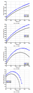
Figure 2: 90% coverage requirement, α3dB = 65◦.
As seen in Figure 2c, the optimum altitude values for dB in rural and urban scenarios are 2300 m and 2000 m, respectively. In the case of s = 15.9 dB (Figure 2d), the optimum altitude values decrease further and become 1200 m for rural scenario and 1100 m for urban scenario. Under the results achieved, we conclude that it is possible to obtain an optimum altitude value for providing a certain QoS through the largest service area.
Then, we increase the coverage ratio requirement to 99% to understand the effect of QoS expectation on coverage radius. In Figure 3, we observe that for each SNR level, coverage area gets slightly smaller with increasing coverage ratio requirement. This result is quite intuitive regarding to both theoretical coverage expression proposed in (11) and the general understanding of wireless communications. We also emphasize that maximum urban area radius that can be served with the largest SNR level decreases when we require a coverage ratio of 99%.
Finally, we analyze the effect of antenna directivity on the coverage radius. In Figure 4, we fix s=15.9 dB and consider a variable beam angle. For each configuration, it is observed that coverage radius enlarges with the increasing beam angle (decreasing directivity) whereas function characteristics do not change much. However, it is important to emphasize that a narrower coverage area would be preferred for certain mission critical services. In addition, for a multi-UAV base station network, narrow beams may be required to limit the intercell interference from time to time. Thereupon, a configurable directivity pattern seems to be a plus for UAV networks.
5. Conclusion
In this paper, we study on downlink indoor coverage performance of UAV base stations. According to the system model proposed, we accept SNR as the primary performance criterion. For the channel, we employ a two-staged model in which outdoor and indoor losses are assumed to be probabilistic and deterministic, respectively. Then, by employing the system model specified, we express the coverage ratio in terms of UAV altitude, cell radius and SNR requirement. In addition, to support our theoretical findings, we share our extensive simulation results. Throughout our simulations, we investigate the effect of UAV altitude, SNR and coverage ratio requirements, and antenna directivity on the coverage radius. According to our simulation results and observations, we conclude that it is possible to choose the UAV altitude level that optimizes the coverage radius. Finally, we note that we aim to build a practical test setup in order to build our own air-to-ground channel model to utilize in our future studies.
Conflict of Interest
The authors declare no conflict of interest.

Figure 3: 99% coverage requirement, α3dB = 65◦.
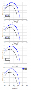
Figure 4: 99% coverage requirement, s=15.9 dB.
- M. Demirtas¸, F. Demirtas ̧, F. Aydın, G. Tanıs ̧, C. Arslan, “Indoor Coverage Analysis for Unmanned Aerial Vehicle Base Stations,” in 2019 27th Signal Process- ing and Communications Applications Conference (SIU), 1–4, 2019, doi: 10.1109/SIU.2019.8806575.
- T. C. Tozer, D. Grace, “High-altitude platforms for wireless communications,” Electronics Communication Engineering Journal, 13(3), 127–137, 2001, doi: 10.1049/ecej:20010303.
- I. Bor-Yaliniz, H. Yanikomeroglu, “The New Frontier in RAN Heterogeneity: Multi-Tier Drone-Cells,” IEEE Communications Magazine, 54(11), 48–55, 2016, doi:10.1109/MCOM.2016.1600178CM.
- M. Alzenad, A. El-Keyi, F. Lagum, H. Yanikomeroglu, “3-D Placement of an Unmanned Aerial Vehicle Base Station (UAV-BS) for Energy-Efficient Maxi- mal Coverage,” IEEE Wireless Communications Letters, 6(4), 434–437, 2017, doi:10.1109/LWC.2017.2700840.
- A. Al-Hourani, S. Kandeepan, S. Lardner, “Optimal LAP Altitude for Maxi- mum Coverage,” IEEE Wireless Communications Letters, 3(6), 569–572, 2014, doi:10.1109/LWC.2014.2342736.
- A. Al-Hourani, S. Kandeepan, A. Jamalipour, “Modeling air-to-ground path loss for low altitude platforms in urban environments,” in 2014 IEEE Global Communications Conference, 2898–2904, 2014, doi:10.1109/GLOCOM.2014. 7037248.
- J. Holis, P. Pechac, “Elevation Dependent Shadowing Model for Mobile Communications via High Altitude Platforms in Built-Up Areas,” IEEE Transactions on Antennas and Propagation, 56(4), 1078–1084, 2008, doi: 10.1109/TAP.2008.919209.
- Q. Feng, J. McGeehan, E. K. Tameh, A. R. Nix, “Path Loss Models for Air-to-Ground Radio Channels in Urban Environments,” in 2006 IEEE 63rd Vehicular Technology Conference, volume 6, 2901–2905, 2006, doi: 10.1109/VETECS.2006.1683399.
- D. W. Matolak, R. Sun, “Air–Ground Channel Characterization for Unmanned Aircraft Systems—Part I: Methods, Measurements, and Models for Over-Water Settings,” IEEE Transactions on Vehicular Technology, 66(1), 26–44, 2017, doi:10.1109/TVT.2016.2530306.
- R. Sun, D. W. Matolak, “Air–Ground Channel Characterization for Unmanned Aircraft Systems Part II: Hilly and Mountainous Settings,” IEEE Transactions on Vehicular Technology, 66(3), 1913–1925, 2017, doi:10.1109/TVT.2016.
2585504. - D. W. Matolak, R. Sun, “Air–Ground Channel Characterization for Unmanned Aircraft Systems—Part III: The Suburban and Near-Urban Environments,” IEEE Transactions on Vehicular Technology, 66(8), 6607–6618, 2017, doi: 10.1109/TVT.2017.2659651.
- A. V. Savkin, H. Huang, “Deployment of Unmanned Aerial Vehicle Base Stations for Optimal Quality of Coverage,” IEEE Wireless Communications Letters, 1–1, 2018, doi:10.1109/LWC.2018.2872547.
- M. Alzenad, H. Yanikomeroglu, “Coverage and Rate Analysis for Unmanned Aerial Vehicle Base Stations with LoS/NLoS Propagation,” in 2018 IEEE Globecom Workshops (GC Wkshps), 1–7, 2018.
- B. Jadhavar, T. Sontakke, “2.4 GHz propagation prediction models for in- door wireless communications within building,” International Journal of Soft Computing and Engineering (IJSCE), 2(3), 108–113, 2012.
- ITU, “Propagation data and prediction methods for the planning of indoor radiocommunication systems and radio local area networks in the frequency range 900 MHz to 100 GHz,” ITU-R Recommendation, 1238, 2012.
- E. Semaan, F. Harrysson, A. Furuska¨r, H. Asplund, “Outdoor-to-indoor cov- erage in high frequency bands,” in 2014 IEEE Globecom Workshops (GC Wkshps), 393–398, 2014, doi:10.1109/GLOCOMW.2014.7063463.
- I. Rodriguez, H. C. Nguyen, I. Z. Kova´cs, T. B. Sørensen, P. Mogensen, “An Empirical Outdoor-to-Indoor Path Loss Model From Below 6 GHz to cm- Wave Frequency Bands,” IEEE Antennas and Wireless Propagation Letters, 16, 1329–1332, 2017, doi:10.1109/LAWP.2016.2633787.
- T. ETSI, “136 101,“,” LTE; Evolved Universal Terrestrial Radio Access (E- UTRA); User Equipment (UE) radio transmission and reception (3GPP TS 36.101 version 14.8. 0 Release 14), 10, 0, 2018.
- T. ETSI, “136 942,“,” LTE; Evolved Universal Terrestrial Radio Access (E- UTRA); Radio Frequency (RF) system scenarios (3GPP TR 36.942 version 10.2. 0 Release 10), 10, 0, 2011.
- M. Taranetz, T. Blazek, T. Kropfreiter, M. Muller, S. Schwarz, M. Rupp, “Runtime Precoding: Enabling Multipoint Transmission in LTE-Advanced System-Level Simulations,” IEEE Access, 3, 725–736, 2015, doi:10.1109/ ACCESS.2015.2437903.
- R. Sheldon, et al., A first course in probability, Pearson Education India, 2002.
- T. 3GPP, “36.888,“,” Technical Specification Group Radio Access Network; Study on provision of low-cost Machine-Type Communications (MTC) User Equipments (UEs) based on LTE (3GPP TS 36.888 version 12.0. 0 Release 12), 06, 0, 2013.