Performance Evaluation Reprogrammable Hybrid Fiber-Wireless Router Testbed for Educational Module
 , Fairuz Abdullah 1, 2
Adv. Sci. Technol. Eng. Syst. J. 6(1), 1199–1207 (2021);
 DOI: 10.25046/aj0601136
Fiber-Wireless (FiWi) network is an integration of fiber optic and wireless connections in the same network. It is one of the best solutions to overcome rapid increment of Internet users and bandwidth-hungry services. To facilitate fundamental knowledge and further understanding on FiWi for students and researchers at the university level, this article proposes the development of a fast integration and scalable FiWi router testbed using Raspberry Pis as the embedded system-based hardware for lab-scale experiments. The performance of the router testbed in terms of end-to-end delay and throughput for upstream and downstream are evaluated. The delay values comply with IEEE 802.15.4 routing scheme. The performance of the router testbed is compared with the industrial grade off-the-shelf router in terms of throughput for each network. A testbed stress test is conducted by sending two data traffics simultaneously, and the performance test is repeated for Wireless-Fiber-Wireless and Fiber-Wireless-Fiber network architecture. The results show the proposed router testbed is scalable, flexible, and capable of fast integration.
1. Introduction
This paper is an extension of work originally presented in 2020 IEEE 8th International Conference on Photonics (ICP) [1]. However, in that work, fiber connection alone would not be able to accommodate all connections, especially to mobile and smart devices that are rapidly increasing. Furthermore, the demand for Internet and leased line bandwidth are growing continuously at more than 20% per year due to more video streaming, cloud computing, social media and mobile data delivery [2]. By 2020, the bandwidth demand will continue to grow due to an enhancement of video quality such as 8K Ultra High Definition (UHD) and increasing number of user subscriptions. Because of that, the estimated traffic in terms of mobile data and fixed systems will be 2600 times more than the traffic in 2010 [2]. This growth is accelerated by the new type of communication services such as device-to-device (D2D) and machine-to-machine (M2M) [3]. Therefore, to ensure users experience are at the same level of Quality of Service (QoS) regardless the time and location while the demand is increasing, Fiber-Wireless (FiWi) deployment has become a necessity because it can cover a large area and support large number of users. According to [4], FiWi is still an ongoing study and there are plenty of rooms for improvement.
It is important to equip fundamental knowledge and further understanding on FiWi for students and researchers at the university level. Therefore, to facilitate this, it is essential to have a scalable FiWi testbed with fast integration capability, which is proposed in this article. FiWi network is a combination of fiber and wireless connection in the same network [5, 6] to provide fixed and mobile services [7-11]. A typical FiWi network consists of high-capacity passive optical network (PON) as backhaul comprising of Optical Line Terminal (OLT) and multiple Optical Network Units (ONU), connected to a cluster of wireless front end routers [12]. ONU is integrated with a wireless gateway that provides wide-area connectivity to users. At the optical backhaul, the OLT at the central office (CO) forms a root connected to the optical backbone via fiber link to provide cloud computing services. ONU is connected to the OLT via 1 : N (N = 32, 64) splitter to form a leaf-shaped nodes. The CO is responsible to manage the information transmission between mobile devices with ONUs and acts as a gateway to other networks [13]. In the wireless end of FiWi network, mobile devices such as smart phones [14, 15], virtual reality (VR) glasses [16], smart watches and other Internet of Things (IoT) devices [16-18] have access to the Internet either via ONU or multi-hop wireless mesh network. Based on a study by [19], one of the advantages of FiWi is that it provides high speed optical backhaul for a wireless mesh network. In [20] stated that the network has a broadband access where it uses wide range of frequencies enabling a large number of data to communicate simultaneously. Whereas, mobile backhaul combines reliability and capacity of Ethernet-based optical backhaul with the wide range of coverage and flexibility of Ethernet-based wireless devices. By utilizing the efficacy of both optical fiber and wireless, a fast speed and low cost of service areas can be achieved [21]. It provides cost effectiveness, robustness, flexibility, high capacity, reliability and self-organization compared to fiber or wireless connection alone [22-24] Another advantage of having FiWi network is the combination of fiber optic and radio access technologies in multi-tier Radio Access Network (RAN) [2].
Radio access technologies will be used to deliver wireless services with high capacity, high link speed, and low latency [25]. The multi-tier RAN will improve the cell edge performance for mobile fronthaul and backhaul, resource sharing, and centralization of multiple standards with different frequency bands and modulation formats. FiWi network is a promising technology to support high demand of bandwidth and large number of users in different types of topologies and geographical environments.
Over the years, research communities have been working hard to improve the performance of FiWi network. Hence, in order to study and perform an extensive performance evaluation, testbeds are needed. Testbed is known as a prototype for proof-of-concept of any technology features where further studies can still be conducted [26]. There are various types of testbed in various platforms such as lab-scale testbed and field testbed. According to [27], built in lab-scale testbed is portable, which means, it can easily be packed away, securely stored and safely transported. The testbed can also be reused and assembled by other researchers in the future. For field testbeds, they consist of high-end setup which require installation by trained professionals and usually require large spaces. For example, in [28], an experiment was conducted consisting of 64 massive multiple-input multiple-output (MIMO) antennas for the FiWi testbed setup. The setup is comparing with collocated massive MIMO to simultaneously serves many users using the same time-frequency resource. For educational module, a simpler setup is preferable because fast integration capability is an important criterion for an educational testbed. This will speed up the installation of the testbed and the lecturers can have more time on explaining rather than focusing on testbed installation.
A testbed can have flexible architecture to be connected to any devices such as multiple sensors [29]. Despite of its compactness, it has powerful local computation unit. A testbed can also be reconfigured to different topologies as required. A review on two types of router testbeds (commercial-based and embedded system-based) were presented in [30]. The commercial-based are store-bought off-the-shelf routers [31, 32]. Some examples of embedded system-based routers are using netFPGA [33], Banana Pi [34] and Raspberry Pi [35-37]. From the study in [30], the embedded system-based routers are reconfigurable, reprogrammable, scalable and cost less than the commercial routers. These advantages will be a suitable choice for the lab-scale router testbed in research and academic field.
Developing a lab-scale testbed is also one of the practical ways of studying and experimenting a particular technology before an actual implementation due to its portability and flexibility. This article describes the development of a FiWi router testbed with the said advantages, with several additional features: fast integration capability, scalable and flexible. The proposed router testbed uses Raspberry Pi for its programmable function (coded in Python language) to be a router. The details of the router structure will be described in the following section.
2. Hybrid Fiber-Wireless Router Testbed
Figure 1 shows a flowchart that reflects the overview of technical development for the proposed router testbed. Firstly, after the proposed routers in the testbed are connected with one another in FiWi architecture, connection reliability test is done by sending a packet from one client to another client. If the packet is not received by the client, an additional processing delay is increased in the proposed router. This delay is an additional time for the router to process the packets including label injecting, label checking, and packet forwarding. The process is repeated until the clients are able to receive the packet without fail. Afterwards, the performance of the proposed router is tested in FiWi architecture in terms of throughput and end-to-end delay in order to validate its correctness and comply with the current communication standards. After it is validated, a stress test is done by sending two traffics at a time to test the stability of the proposed router. Then, the architecture is changed to Fi-WiFi and Wi-FiWi in order to test its flexibility and scalability.
The proposed FiWi router testbed is using Raspberry Pi 3B+ to support data transmission for research and education purposes. It consists of four routers that are connected in tree topology and may be varied accordingly, as shown in Figure 2. It is a typical topology for FiWi network [12, 13]. Each router is an integration of four Raspberry Pi 3B+; one Header Pi and three Forwarding Pis. The three Forwarding Pis are to emulate the real router, with each of them having a unique static IP address. To form a router, the Raspberry Pis will be connected to two Ethernet switches via CAT5e Ethernet cable, as illustrated in Figure 3. Ethernet Switch 1 is to represent the internal connection of the routers (between Header Pi and Forwarding Pis). While Ethernet Switch 2 representing the external connection between routers. An Access Point (AP) is added as an element to the router structure to support wireless transmission.
2.1. Topology
The router testbed is set up in tree topology consisting of four proposed routers for the default FiWi architecture, as shown in Figure 2. The connection between routers is using single mode fiber optic patch cord. Since Raspberry Pi has only one Ethernet port, a Fiber Media Converter (FMC) is needed as an adapter. Then, the architecture is expanded to Fi-WiFi and Wi-FiWi as shown in Figure 4 and Figure 5, respectively. Compared to other topologies such as ring and mesh, the flexibility and stability of the proposed router can be observed after going through a number of medium changes from wireless to fiber and vice versa in tree topology. Moreover, the purpose of these setups is to test the scalability of the testbed.
 Figure 1: The overall flowchart of this work
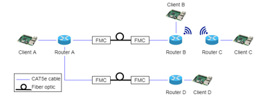 Figure 2: The architecture of FiWi router testbed
The architecture of this testbed can be scaled easily to Fi-WiFi and Wi-FiWi without any tedious hardware rearrangement. The routing mechanism for FiWi, Fi-WiFi and Wi-FiWi can be achieved by changing the label for each client, Header Pi and Forwarding Pi in the router program code. The labels for routers and clients in any of the three architectures (FiWi, Fi-WiFi and Wi-FiWi) must be unique to prevent misinterpretation of data destination by the router.
2.2. Routing Mechanism
The flowcharts of the testbed routing mechanism are shown in Figure 6, 7 and 8, for the client, Header Pi and Forwarding Pi, respectively. When a client sends a packet of data to the destination, a pre-label is added to the payload of the packet to indicate where the data should end. The client sends the data to Header Pi. Then, the Header Pi checks the label to know the beginning (source) and end (destination) of the data. After the Header Pi has identified the destination of the data, it replaces the old label with a new label onto the payload and then broadcast the data to each Forwarding Pis. Each of the Forwarding Pi has its own unique label because each identity label corresponds to one destination only. When the Forwarding Pi receives data from Header Pi, it will check the label on the payload of the packet with its own identity label. If both labels are the same, the Forwarding Pi will continue to forward the data to desired destination set by the client. Otherwise, if both labels are not the same, the Forwarding Pi turns the data to zero and drops the packet.
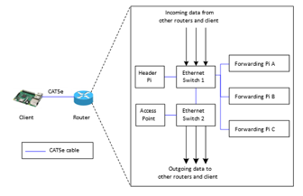 Figure 3: The structure of proposed router
 Figure 4: The architecture for Fi-WiFi router testbed
 Figure 5: The architecture for Wi-FiWi router testbed
2.3. Experimental Setup
2.3.1. FiWi Router Testbed Performance Test
For this test, Raspberry Pi client is used to send a packet to another client via a combination of fiber and wireless transmission as in Figure 2. The initial data size transmitted is at 100 bytes for proof of concept [38]. Then, the data size is increased by 100 bytes each time until 1445 bytes. The performance of the experiment in terms of end-to-end delay and throughput are plotted on the graph. The proposed router is compared with industrial grade router to check its functionality and to observe its correctness. The setup for the industrial grade router is using the same topology as the proposed testbed. The upstream and downstream transmissions are done by using two computers. The throughput of the proposed router testbed is validated with industrial grade router. The bandwidth of the industrial grade router is set to 1 Gbps. However, the initial data size is set to 10 kB and increased by 10 kB for each transmission until 100 kB. This is because the industrial grade router is connected to an access point with similar specification to the proposed testbed setup, limiting the actual bandwidth to 1 Mbps. Then, the throughput of the experiment for upstream and downstream are captured using Wireshark.
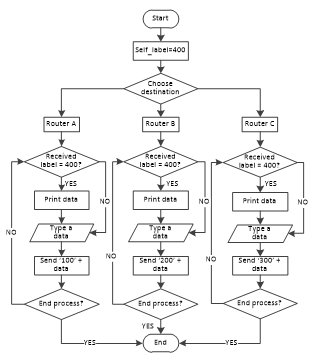 Figure 6: Client flowchart
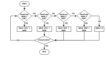 Figure 7: Header Pi flowchart
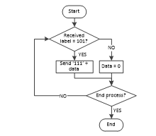 Figure 8: Forwarding Pi flowchart (label example for A)
2.3.2. FiWi Router Testbed Stress Test
The limit of the FiWi router testbed is tested by sending two traffics simultaneously from one router to another. This stress test is done by connecting two clients for each proposed router. The performance will be analysed in terms of the end-to-end delay and throughput for downstream and upstream for two simultaneous traffic transmission. The purpose of this test is to evaluate the stability of the proposed testbed.
2.3.3. Scalability Test
Scalability is defined as the ability for the testbed to adapt to a new architecture or arrangement easily and its ability to expand the number of new components. In order to add or remove a component in the testbed, minor changes need to be done to its arrangement. In this case, the testbed architecture is changed to Fi-WiFi and Wi-FiWi to test its scalability performance and to prove the testbed is flexible to work in various architecture. The scalability test presents the performance for Fi-WiFi and Wi-FiWi in terms of end-to-end delay and throughput. Hence, the purpose of this section is to analyse the scalability performance and to compare which architecture is better for the testbed.
2.4. Parameters
2.4.1. Design
Design parameters are defined as the input for the testbed; the data size and the end-to-end delay. The data size is the length of data in bytes (B). It can be varied easily by the user at the client side. In this experiment, the increment of the transmitted data size is 100 bytes for each transmission. The summary of data size and corresponding throughput scale used in the experiment are listed in Table 1. The data size affects the end-to-end delay where greater data size may result in greater end-to-end delay. The end-to-end delay is used to study the throughput of the testbed.
Table 1: Summary of data size and throughput scale used in the testbed experiment
| Start | Data size increment | End | Throughput scale | |
| Proposed testbed | 100 bytes | 100 bytes | 1445 bytes | linearly |
| Industrial grade router | 10 kB | 10 kB | 100 kB | 1 |
2.4.2. Performance
Performance parameters are the output of the testbed which indicate its performance. Two performance parameters are taken into consideration; end-to-end delay and throughput. End-to-end delay is the time taken when the user sends the data from a client to another client. Throughput is the overall performance of the testbed in bit per second (bps) when the data size in bit (b) is divided by end-to-end delay, L, in second (s). The throughput, ThTL calculation is summarized in (1) [39], where DT is data transmitted and DL is data loss. 3. Results and Discussion
3.1. Fiber-Wireless Performance Test
Figure 9 shows the throughput for downstream and upstream transmissions. The purpose of this validation is to observe the correctness of the router testbed. The throughput of the testbed is scaled up to match the throughput industrial grade router. Based on the figure, the throughput of the proposed testbed has similar increasing trend as the industrial grade router, thus validates the correctness. The downstream throughput for proposed testbed increases from 0 bps at 0% offered load to 719 kbps at 100% offered load. The throughput of industrial grade router increases from 0 bps at 0% offered load to 697 kbps at 90%, then decreases at 100% offered load when reaching its bandwidth limit. This situation is due to the QoS algorithm in the industrial grade router limits the maximum throughput.
Similar trend is observed for upstream transmission, where the throughput of the proposed testbed increases as the offered load increases from 0 bps to 770.351 kbps at 0% to 100% offered load. The throughput for industrial grade router is also increasing from 0 bps to 774 kbps at 0% to 100% offered load.
For both downstream and upstream transmissions, industrial grade router is able to transmit data up to 700 kbps and 774 kbps respectively at 100% offered with 1445 bytes of in each packet. But the proposed testbed can only transmit for one packet of 1445 bytes, up to 52.097 kbps for downstream transmission and 54.335 kbps for upstream transmission. Hence, if the proposed testbed sends as many packets as the industrial grade router, the transmitted data in the proposed testbed is vertically scaled up by factor of 13.436 (700 kbps/59.097 kbps = 13.436) for downstream and 12.883 for upstream (774 kbps/59.097 kbps = 13.436). Vertical scaling is a method to translate a graph without losing the original properties where all y-values in the graph are multiplied by a specific factor. Therefore, for the proposed testbed, the throughput for each offered load is multiplied with 13.436 and 12.883 for downstream and upstream respectively.
Overall, the throughput of the proposed testbed is slightly lesser than the industrial grade router due to its lower technical specification, bandwidth and processing power but is adequate enough for lab-scale experiment. From the graphs, we can conclude that the trend of the proposed testbed is correct.
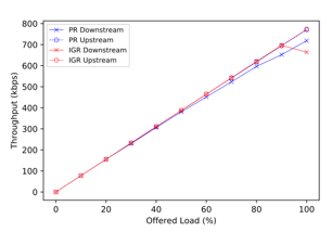 Figure 9: FiWi downstream and upstream throughput for the proposed router (PR) testbed and the industrial grade router (IGR)
Figure 10 shows the end-to-end delay for downstream and upstream transmission in FiWi architecture. For downstream, the minimum and maximum end-to-end delay are 0.1246 s and 0.14484 s at 100 bytes and 1445 bytes, respectively. For upstream, the minimum end-to-end delay is 0.12193 s at 100 bytes, and the maximum is 0.12430 s at 1445 bytes. The increased delay is due to testbed takes longer time to process the data. The subtle differences in the graphs caused by very small data size for a large bandwidth of fiber (1 Gbps). Furthermore, the data is transmitted by using light pulses in fiber. Hence, it transmits faster compared to electrical pulses in copper. For example, during downstream transmission, the end-to-end delay at 100 bytes is 0.1246 s, whereas at 200 bytes the end-to-end delay is 0.1250 s. The end-to-end delay is expected to be higher in the proposed router testbed compared to a typical fiber-supported router like industrial grade router, also because of hardware limitation. This is acceptable as part of the aim of this article is to create a reconfigurable router testbed that supports fiber-wireless transmission for educational module.
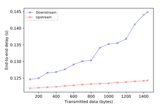 Figure 10: FiWi downstream and upstream end-to-end delay
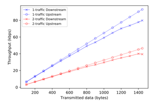 Figure 11: FiWi stress test downstream and upstream throughput for 1-traffic and 2-traffics transmissions
3.2. Fiber-Wireless Stress Test
Figure 11 shows the throughput for downstream and upstream transmissions. The throughput is still increasing gradually with the data size. The minimum and maximum throughput are 3.210 kbps at 100 bytes and 40.047 kbps at 1400 bytes. For downstream with 2 traffics, the throughput decreases at 1445 bytes from 40 kbps to 39.5 kbps due to the end-limit of the testbed. Compared with the throughput of a single traffic, the throughput of two traffics is about half of the throughput of single traffics. The reason of this occurrence is two traffics causing the proposed testbed to process the data twice. For example, at 100 bytes in downstream transmission, the throughput for a single traffic is 6.42 kbps whereas the throughput for two traffics is 3.21 kbps. This statement is supported by [40] where more traffics contribute to less throughput.
Figure 12 shows the downstream and upstream end-to-end delay graphs. For downstream, the trend of the graph is increasing with the data size, from 0.249 s at 100 bytes to 0.293 s at 1445 bytes. At 1445 bytes, there is a sudden increase of end-to-end delay, due to the testbed’s end-limit. Theoretically, when number of traffics increases, the end-to-end delay also increases [41]. Therefore, comparing the plots for downstream, the end-to-end delay of two traffics is twice as big as single traffic, because testbed needs to process the data twice. For example, the end-to-end delay at 1445 bytes for single traffic and two traffics are 144.838 ms and 293.01 ms, respectively.
The trend for upstream end-to-end delay is also similar where the delay increases from 243.863 ms at 100 bytes to 248.591 ms at 1445 bytes. At 1445 bytes, the end-to-end delay for two traffics and single traffic are 248.591 ms and 124.296 ms, respectively. Even though the trends of the graphs are almost constant, it is actually increasing as the data increases. The constant trends of the graphs are due to the presence of fiber which make the difference in end-to-end delay between two data such as 100 bytes and 200 bytes are not significant.
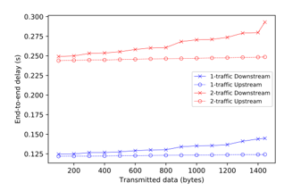 Figure 12: FiWi stress test downstream and upstream end-to-end delay for 1-traffic and 2-traffics transmissions
3.3. Scalability Test
3.3.1. Fiber-Wireless-Fiber
The plot for Fi-WiFi downstream and upstream throughput is shown in Figure 13. The downstream throughput increases with the data size from 2.626 kbps at 100 bytes to 22.403 kbps at 1445 bytes. For upstream, the throughput is increasing up until 1100 bytes only, unstable at 1200 bytes to 1300 bytes, then continue to decrease from 1400 bytes to 1455 bytes. Even though the downstream throughput is increasing, but the graph gradient is gradually decreasing starting at 700 bytes. Whereas the upstream throughput becomes unstable at 1200 bytes to 1300 bytes because the proposed testbed is almost at its limit, resulting in greater graph gradient. Then, the throughput decreases at 1400 bytes and 1445 bytes due to the sudden increase of upstream end-to-end delay at 1400 bytes in and the delay continues to increase until 1445 bytes.
The downstream and upstream end-to-end delay for Fi-WiFi architecture is shown in Figure 14. The downstream delay increases with the data size from 0.609 s at 100 bytes to 1.032 s at 1445 bytes. For upstream, the increases from 0.505 s at 100 bytes to 0.948 s at 1445 bytes. The end-to-end delay for this setup is higher than the FiWi architecture because the data has to undergo multiple routers and medium conversions from fiber to wireless and then wireless to fiber [42]. For downstream transmission, there is a sudden increase in end-to-end delay at 1400 bytes due to the end-limit of the proposed testbed, thus the longer processing time.
3.3.2. Wireless-Fiber-Wireless
The downstream and upstream throughput for Wi-FiWi architecture can be seen in Figure 13. The trend of the downstream throughput increases with the transmitted data size from 2.833 kbps at 100 bytes to 38.09 kbps at 1445 bytes. For upstream, the throughput increases from 2.81 kbps at 100 bytes to 38.348 kbps at 1445 bytes. At 100 bytes, the throughput for upstream transmission is slightly lower than downstream. However, as the transmitted data increases, the throughput for upstream transmission is higher than downstream: the throughput at 1100 bytes is 29.754 kbps (upstream) and 29.941 kbps (downstream). However, starting 1200 bytes, the throughput for upstream transmission is 32.276 kbps, while for downstream is 32.087 kbps. At 1445 bytes, the performance for both transmissions are slightly decreased due to the end-limit of the testbed, referring to the slope of the graph at this point. The slight differences in the throughput values proving that the proposed testbed in Wi-FiWi architecture is stable for both transmissions. This proposed router testbed is therefore suitable to be a scalable testbed.
Figure 14 shows the end-to-end delay of downstream and upstream transmissions respectively for Wi-FiWi architecture. The downstream end-to-end delay increases with the transmitted data size from 0.565 s at 100 bytes to 0.607 s at 1445 bytes. There is a sudden increase to the downstream end-to-end delay at 1200 bytes, because the proposed testbed is approaching its limit. Hence, the data processing time takes longer at this point. For upstream, the end-to-end delay is also increasing with the transmitted data, from 0.569 s at 100 bytes to 0.603 s at 1445 bytes. It can be observed that the downstream and upstream end-to-end delay for Wi-FiWi architecture is also higher than the FiWi because there are more medium changes in between clients. Therefore, the process of medium conversion contributes to higher end-to-end delay.
3.3.3. Fi-WiFi versus Wi-FiWi
Figure 13 clearly shows the comparisons in terms of throughput between Fi-WiFi and Wi-FiWi architectures for downstream and upstream transmissions from 100 bytes to 1445 bytes. The performance for Wi-FiWi is more stable than Fi-WiFi based on the behaviour of the graphs. This is because Fi-WiFi has more conversion from electrical pulses to light pulses and vice versa compared to Wi-FiWi causing the instability in Fi-WiFi. Thus, the overall performance in Wi-FiWi is more stable because it has better observable graphs compared to Fi-WiFi.
Figure 14 shows the end-to-end delay comparisons between Fi-WiFi and Wi-FiWi architectures for downstream and upstream transmissions. Both have increasing end-to-end delay when the transmitted data size increased from 100 bytes to 1445 bytes. However, Fi-WiFi architecture has higher delay than Wi-FiWi because of the higher number of FMCs in Fi-WiFi. Hence, the medium conversions from light pulses to electrical pulses or vice versa is more than Wi-FiWi, thus contributes to more delay. From the graphs, we can conclude that Wi-FiWi has more stable transmission because throughout the transmissions, the end-to-end delay changes subtly. The summary of the throughput and end-to-end delay results at full load (1445 bytes) for all experiments using the proposed router testbed are listed in Table 2. Throughput results for FiWi architecture are not scaled, to fairly compare with other experiments.
 Figure 13: Fi-WiFi vs Wi-FiWi throughput
 Figure 14: Fi-WiFi vs Wi-FiWi end-to-end delay
4. Conclusion
FiWi is seen to be one of the best technologies for future global data communication network architecture due to the advantages of providing robustness and mobility to the consumers by deploying FIber and wireless in one network. To equip fundamental knowledge and further understanding on FiWi for students and researchers at the university level, this article proposed a FiWi router testbed. It is a fast integration and scalable, which is essential for an educational module testbed. The focus of this research is on lab-scale environment router testbed in FiWi architecture to provide a proof-of-concept solution on reconfigurable router testbed in FiWi network. Raspberry Pi is chosen to be the embedded system hardware in this research for the development of scalable and reconfigurable FiWi router testbed. It has a socket module which enables the user to program Raspberry Pi to communicate with each other using IP addresses.
The proposed FiWi testbed throughput performance has been validated with industrial grade router to prove the correctness. As the proposed testbed approaches its limit, the throughput is maintained with no further increment. For the end-to-end delay, it increases with the data size with acceptable measure and its behaviour satisfies the end-to-end delay of IEEE 802.15.4 routing scheme. Hence, the proposed testbed is suitable to serve as an educational module FiWi testbed due to its simplicity, reconfigurable and fast implementation. A stress test shows that the end-to-end delay for two traffics is twice as high as single traffic due to the twice data processing. This causes the throughput for two traffics is halved of the single traffic throughput. For scalability performance test, the end-to-end delay in Fi- WiFi is higher than Wi-FiWi architecture due to more electrical pulses to light pulses conversion and vice versa from FMC in Fi-WiFi. Furthermore, Wi-FiWi is more stable compared to Fi-WiFi, thus making the testbed flexible and scalable for various possible setups. The proposed router testbed also shows a promising stability, a huge advantage to test various architectures.
Table 2: Summary of throughput and end-to-end delay results at full load (1445 bytes) for all experiments
| Experiment | Parameters | |||
| Throughput (kbps) | End-to-end delay (s) | |||
| Up stream |
Down stream |
Up stream |
Down stream |
|
| FiWi | 54.34 | 59.10 | 0.124 | 0.144 |
| FiWi stress test | 46.50 | 39.45 | 0.250 | 0.290 |
| Fi-WiFi | 24.40 | 22.40 | 0.948 | 1.030 |
| Wi-FiWi | 38.35 | 38.09 | 0.600 | 0.610 |
Conflict of Interest
The authors declare no conflict of interest.
Acknowledgment
The author gratefully acknowledges the funding of Yayasan Canselor UNITEN (201901001YCU/10), and UNITEN R&D Sdn. Bhd. for TNB Seed Fund (U-TD-RD-20-03).
- M. H. M. Nasir, W. S. H. M. W. Ahmad, N. A. M. Radzi, F. Abdullah, A. Abdullah, A. Ismail, and M. Z. Jamaludin, “Raspberry Pi as Reconfigurable Fiber-based Router and Its Performance Analysis,” in 2020 IEEE 8th International Conference on Photonics (ICP), 30-31, 2020, doi:10.1109/ICP46580.2020.9206497.
- M. Tornatore, G.-K. Chang, and G. Ellinas, Fiber-wireless convergence in next-generation communication networks, Springer, 2017.
- E. A. Kosmatos and N. D. Tselikas, “Dominant handover algorithms for vehicular radio-over-fiber networks at 60 GHz: a performance Evaluation study” Performance Evaluation, 102, 21-33, 2016, doi:https://doi.org/10.1016/j.peva.2016.05.001.
- M. Ridwan, N. A. M. Radzi, F. Abdullah, N. M. Din, and C. Rashidi, “Feasibility study of a reconfigurable fiber-wireless testbed using universal software radio peripheral” International Journal of Engineering and Technology Innovation, 8(4), 274-283, 2018,
- N. Ghazisaidi and M. Maier, “Fiber-wireless (FiWi) access networks: challenges and opportunities” IEEE Network, 25(1), 36-42, 2011, doi:10.1109/MNET.2011.5687951.
- M. Maier and N. Ghazisaidi, FiWi access networks, Cambridge University Press, 2011.
- B. P. Rimal, M. Maier, and M. Satyanarayanan, “Experimental testbed for edge computing in fiber-wireless broadband access networks” IEEE Communications Magazine, 56(8), 160-167, 2018, doi:10.1109/MCOM.2018.1700793.
- V. Mishra, R. Upadhyay, and U. R. Bhatt, Progress in Advanced Computing and Intelligent Engineering, Springer, 2018.
- J. Liu, H. Guo, H. Nishiyama, H. Ujikawa, K. Suzuki, and N. Kato, “New perspectives on future smart FiWi networks: scalability, reliability, and energy efficiency” IEEE Communications Surveys & Tutorials, 18(2), 1045-1072, 2015, doi:10.1109/COMST.2015.2500960.
- Y. Liu, L. Guo, B. Gong, R. Ma, X. Gong, L. Zhang, and J. Yang, “Green survivability in fiber-wireless (FiWi) broadband access network” Optical Fiber Technology, 18(2), 68-80, 2012, doi:https://doi.org/10.1016/j.yofte.2011.12.002.
- Q. Dai, G. Shou, Y. Hu, and Z. Guo, “A general model for hybrid fiber-wireless (FiWi) access network virtualization,” in 2013 IEEE International Conference on Communications Workshops (ICC), 858-862, 2013, doi:10.1109/ICCW.2013.6649354.
- Y. Yu, C. Ranaweera, C. Lim, L. Guo, Y. Liu, A. Nirmalathas, and E. Wong, “Hybrid fiber-wireless network: An optimization framework for survivable deployment” Journal of Optical Communications and Networking, 9(6), 466-478, 2017, doi:https://doi.org/10.1364/JOCN.9.000466.
- H. Guo and J. Liu, “Collaborative computation offloading for multi-access edge computing over fiber–wireless networks” IEEE Transactions on Vehicular Technology, 67(5), 4514-4526, 2018, doi:10.1109/TVT.2018.2790421.
- Z. Zhang, J. Kong, C. Huang, Q. Wu, J. Wu, and J. Li, “Virtual network embedding algorithm considering resource fragmentation in virtualized industrial fiber-wireless (FiWi) access network,” in Proceedings of the International Conference on Imaging, Signal Processing and Communication, 148-152, 2017, doi:https://doi.org/10.1145/3132300.3132328.
- H. Beyranvand, W. Lim, M. Maier, C. Verikoukis, and J. A. Salehi, “Backhaul-aware user association in FiWi enhanced LTE-A heterogeneous networks” IEEE Transactions on Wireless Communications, 14(6), 2992-3003, 2015, doi:10.1109/TWC.2015.2399308.
- P. Porambage, J. Okwuibe, M. Liyanage, M. Ylianttila, and T. Taleb, “Survey on multi-access edge computing for internet of things realization” IEEE Communications Surveys & Tutorials, 20(4), 2961-2991, 2018, doi:10.1109/COMST.2018.2849509.
- W. Sun, J. Liu, and H. Zhang, “When smart wearables meet intelligent vehicles: Challenges and future directions” IEEE wireless communications, 24(3), 58-65, 2017, doi:10.1109/MWC.2017.1600423.
- B. P. Rimal, D. P. Van, and M. Maier, “Mobile edge computing versus centralized cloud computing over a converged FiWi access network” IEEE Transactions on Network and Service Management, 14(3), 498-513, 2017, doi:10.1109/TNSM.2017.2706085.
- P.-Y. Chen and M. Reisslein, “FiWi network throughput-delay modeling with traffic intensity control and local bandwidth allocation” Optical Switching and Networking, 28, 8-22, 2018, doi:https://doi.org/10.1016/j.osn.2017.11.001.
- B. P. Rimal, D. P. Van, and M. Maier, “Mobile edge computing empowered fiber-wireless access networks in the 5G era” IEEE Communications Magazine, 55(2), 192-200, 2017, doi:10.1109/MCOM.2017.1600156CM.
- H.-H. Lu, C.-Y. Li, T.-C. Lu, C.-J. Wu, C.-A. Chu, A. Shiva, and T. Mochii, “Bidirectional fiber-wireless and fiber-VLLC transmission system based on an OEO-based BLS and a RSOA” Optics Letters, 41(3), 476-479, 2016, doi:https://doi.org/10.1364/OL.41.000476.
- P. Singh and S. Prakash, “Optical network unit placement in Fiber-Wireless (FiWi) access network by Moth-Flame optimization algorithm” Optical Fiber Technology, 36, 403-411, 2017, doi:https://doi.org/10.1016/j.yofte.2017.05.018.
- B. Kantarci, N. Naas, and H. T. Mouftah, “Energy-efficient DBA and QoS in FiWi networks constrained to metro-access convergence,” in 2012 14th International Conference on Transparent Optical Networks (ICTON), 1-4, 2012, doi:10.1109/ICTON.2012.6253908.
- M. Lévesque, M. Maier, F. Aurzada, and M. Reisslein, “Analytical framework for the capacity and delay evaluation of next-generation FiWi network routing algorithms,” in 2013 IEEE Wireless Communications and Networking Conference (WCNC), 1926-1931, 2013, doi:10.1109/WCNC.2013.6554859.
- J. Liu, H. Guo, Z. M. Fadlullah, and N. Kato, “Energy consumption minimization for FiWi enhanced LTE-A HetNets with UE connection constraint” IEEE Communications Magazine, 54(11), 56-62, 2016, doi:10.1109/MCOM.2016.1600169CM.
- N. Choosri, Y. Park, S. Grudpan, P. Chuarjedton, and A. Ongvisesphaiboon, “IoT-RFID testbed for supporting traffic light control” International Journal of Information and Electronics Engineering, 5(2), 102-106, 2015, doi:10.7763/IJIEE.2015.V5.511.
- W. Hurst, N. Shone, A. El Rhalibi, A. Happe, B. Kotze, and B. Duncan, “Advancing the micro-CI testbed for IoT cyber security research and education,” in The Eighth International Conference on Cloud Computing, GRIDs, and Virtualization, 129-134, 2017.
- S. T. Abraha, D. F. Castellana, X. Liang, A. Ng’oma, and A. Kobyakov, “Experimental study of distributed massive MIMO (DM-MIMO) in in-building fiber-wireless networks,” in 2018 Optical Fiber Communications Conference and Exposition (OFC), 1-3, 2018,
- Z. Gong, W. Xue, Z. Liu, Y. Zhao, R. Miao, R. Ying, and P. Liu, “Design of a reconfigurable multi-sensor testbed for autonomous vehicles and ground robots,” in 2019 IEEE International Symposium on Circuits and Systems (ISCAS), 1-5, 2019, doi:10.1109/ISCAS.2019.8702610.
- M. H. M. Nasir, N. A. M. Radzi, W. S. H. M. W. Ahmad, F. Abdullah, and M. Z. Jamaludin, “Comparison of router testbeds: embedded system-based, software-based, and multiprotocol label switching (MPLS)” Indonesian Journal of Electrical Engineering and Computer Science, 15(3), 1250-1256, 2019, doi:http://doi.org/10.11591/ijeecs.v15.i3.pp1250-1256.
- S. M. Blair, F. Coffele, C. Booth, B. De Valck, and D. Verhulst, “Demonstration and analysis of IP/MPLS communications for delivering power system protection solutions using IEEE C37. 94, IEC 61850 sampled values, and IEC 61850 GOOSE protocols,” in 2014 CIGRE Session, 1-8, 2014.
- K. Tantayakul, R. Dhaou, B. Paillassa, and W. Panichpattanakul, “Experimental analysis in SDN open source environment,” in 2017 14th International Conference on Electrical Engineering/Electronics, Computer, Telecommunications and Information Technology (ECTI-CON), 334-337, 2017, doi:10.1109/ECTICon.2017.8096241.
- V. Sivaraman, A. Vishwanath, D. Ostry, and M. Thottan, “Greening router line-cards via dynamic management of packet memory” IEEE Journal on Selected Areas in Communications, 34(12), 3843-3853, 2016, doi:10.1109/JSAC.2016.2600412.
- D. Posch, B. Rainer, S. Theuermann, A. Leibetseder, and H. Hellwagner, “Emulating NDN-based multimedia delivery,” in Proceedings of the 7th International Conference on Multimedia Systems, 1-4, 2016. doi:https://doi.org/10.1145/2910017.2910626.
- S. Y. Jang, B. H. Shin, and D. Lee, “Implementing a dynamically reconfigurable wireless mesh network testbed for Multi-Faceted QoS support,” in Proceedings of the 11th International Conference on Future Internet Technologies, 95-98, 2016, doi:https://doi.org/10.1145/2935663.2935678.
- X. Piao, L. Huang, K. Yuan, J. Yuan, and K. Lei, “The real implementation of NDN forwarding strategy on android smartphone,” in 2016 IEEE 7th Annual Ubiquitous Computing, Electronics & Mobile Communication Conference (UEMCON), 1-6, 2016, doi:10.1109/UEMCON.2016.7777909.
- V. Gupta, K. Kaur, and S. Kaur, “Developing small size low-cost software-defined networking switch using Raspberry Pi,” in 50th Annual Convention of Computer Society of India : Next-Generation Networks, 147-152, 2018, doi:https://doi.org/10.1007/978-981-10-6005-2_16.
- S. Brown, “An analysis of loss-free data aggregation for high data reliability in wireless sensor networks,” in 2017 28th Irish Signals and Systems Conference (ISSC), 1-6, 2017, doi:10.1109/ISSC.2017.7983622.
- J. Padhye, V. Firoiu, D. Towsley, and J. Kurose, “Modeling TCP throughput: a simple model and its empirical validation,” in Proceedings of the ACM SIGCOMM’98 Conference on Applications, Technologies, Architectures, and Protocols for Computer Communication, 303-314, 1998, doi:https://doi.org/10.1145/285237.285291.
- H. Xu, X.-Y. Li, L. Huang, H. Deng, H. Huang, and H. Wang, “Incremental deployment and throughput maximization routing for a hybrid SDN” IEEE/ACM Transactions on Networking, 25(3), 1861-1875, 2017, doi:10.1109/TNET.2017.2657643.
- Q. T. Minh, T. K. Dang, T. Nam, and T. Kitahara, “Flow aggregation for SDN-based delay-insensitive traffic control in mobile core networks” IET Communications, 13(8), 1051-1060, 2019, doi:10.1049/iet-com.2018.5194.
- M. A. Abidini, O. Boxma, C. Hurkens, T. Koonen, and J. Resing, “Revenue maximization in optical router nodes” Performance Evaluation, 140, 102-108, 2020, doi:https://doi.org/10.1016/j.peva.2020.102108.